Advertisement
Available languages
Available languages
Advertisement
Table of Contents

Related Manuals for Peavey TMax


Summary of Contents for Peavey TMax
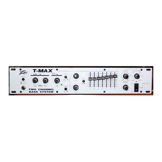
- Page 1 Cover for T-MAX™...
- Page 2 Intended to alert the user to the presence of uninsulated "dangerous voltage" within the product's enclosure that may be of sufficient magnitude to constitute a risk of electric shock to persons. Intended to alert the user of the presence of important operating and maintenance (servicing) instructions in the literature accompanying the product.
- Page 3 Congratulations on the purchase of the Peavey T-MAX is unlike any other amp available today. Not only does the T-MAX utilize tube technology for that smooth tube sound, but the T-MAX also has a completely independent solid-state channel! Two separate channels that are footswitchable and combinable make for an extremely versatile piece of gear.
- Page 4 INPUT PAD SWITCH (1) Provided for instruments that have extremely high output, which can result in overdriving (distorting) the input gain stage. Depressing the switch to its "in" position reduces the level of the input signal by 10 dB. INPUT (2) This input will accept signals from all types of bass pickups.
- Page 5 POWER LED/DDT™ INDICATOR (18) The LED is green when the power switch is in the "on" position. During normal operation, this LED also acts as a DDT™ indicator. The LED illuminates "red" when DDT™ power amp compression is taking place. POWER SWITCH (19) Used to turn AC mains power on or off.
- Page 6 There may be some situations when audible hum and/or noise will come from the loudspeaker. Select the ground switch to either the in or out position to minimize the noise. POWER AMP INPUT (27) Used to connect line level signal to the power amplifier.
-
Page 7: Specifications
SPECIFICATIONS POWER AMP SECTION Power Output with DDT™ Compression Active: 200 W RMS into 8 ohms 350 W RMS into 4 ohms 500 W RMS into 2 ohms Input Sensitivity: Input signal necessary for full output = 1.7 V RMS DDT™... -
Page 8: Tone Settings
TONE SETTINGS Set Pre and Post Gain so that clip indicator does not light; then use Master Volume for playing level. ROCK FUNK COUNTRY NOTE: Above settings for use with Solid-State or Tube Channel. NOTES FOR TUBE CHANNEL: Distortion: Set Pre Gain very high — usually above 5. Keep Post Gain set low. Clean: Set Post Gain @ 10 and set Pre Gain low —... - Page 9 E S P A Ñ O L SELECCIÓN DE IGUALADOR GRÁFICO (13) Cuando el conmutador está oprimido (IN), éste dirige la señal a través del igualador gráfico. Cuando no está oprimido (OUT), el igualador gráfico está fuera del recorrido de la señal. LED DE ENCENDIDO/INDICADOR DDT™...
- Page 10 produzca algún zumbido y/o ruido audibles. Active o desactive el conmutador del circuito de tierra oprimiéndolo; de esta manera reducirá el ruido. ENTRECRUZAMIENTO (SALIDA BAJA) (29) Proporciona una señal de salida de bajo rango después del entrecruzamiento. El nivel de la señal se ajusta mediante el control de postganancia y el control de equilibrio de entrecruzamiento.
- Page 12 COMMUTATEUR D’ÉGALISATION GRAPHIQUE (13) En position entrée («in»), ce commutateur dirige le signal vers l’égaliseur graphique. La position sortie («out») retire l’égaliseur du chemin du signal. INDICATEUR DEL DE FONCTIONNEMENT/DDT™ (18) La DEL est de couleur verte quand l’interrupteur marche/arrêt est en position marche («on»). Au cours du fonctionnement normal, cette DEL tient aussi lieu d’indicateur DDT™...
- Page 13 SÉPARATEUR (CROSSOVER) (SORTIE BASSES FRÉQUENCES) (29) Il fournit le signal de sortie basses fréquences post-crossover. Le niveau du signal est ajusté par les potentiomètres de gain post et de balance de crossover. SÉPARATEUR (CROSSOVER) (SORTIE HAUTES FRÉQUENCES) (30) Il fournit le signal de sortie hautes fréquences post-crossover. Le niveau du signal est ajusté par les potentiomètres de gain post et de balance de crossover.
- Page 15 D E U T S C H GRAPHIC-AUSWAHLSCHALTER (13) In der „In“-Position wird das Signal durch den graphischen Equalizer geleitet. In der „Out“- Position wird der graphische Equalizer aus dem Signalpfad entfernt. POWER LED/DDT™-ANZEIGE (18) Wenn das Gerät eingeschaltet ist, d. h., wenn sich der Hauptnetzschalter in „On“-Position befindet, leuchtet die LED grün auf.
- Page 16 CROSSOVER (NIEDERFREQUENZ-AUSGANG) (29) An diesem Ausgang liegt ein Post-Crossover-Ausgangssignal im Tieftonbereich an. Der Signalpegel wird durch die Post-Gain-Steuerung (nach Verstärkung) und die Crossover-Balance- Regelung ausgesteuert. CROSSOVER (HOCHFREQUENZ-AUSGANG) (30) An diesem Ausgang liegt ein Post-Crossover-Ausgangssignal im Hochtonbereich an. Der Signalpegel wird durch die Post-Gain-Steuerung (nach Verstärkung) und die Crossover-Balance- Regelung ausgesteuert.
- Page 18 For further information on other Peavey products, ask your Authorized Peavey Dealer for the appropriate Peavey catalog/publication: Bass Guitars Guitars Bass Amplification Guitar Amplification Sound Reinforcement Enclosures Microphones Keyboards Lighting Mixers, Powered/Non-Powered Accessories/Cables Effects Processors Axcess™ Wear The Peavey Beat™...
- Page 19 PEAVEY 90-DAY LIMITED WARRANTY ON TUBES AND METERS If this product contains tubes or meters, Peavey warrants the tubes or meters contained in the product to be free from defects in material and workmanship for a period of ninety (90) days from date of purchase; PROVIDED, however, that this limited warranty is extended only to the original retail purchaser and is also subject to the conditions, exclusions, and limitations hereinafter set forth.
-
Page 20: Important Safety Instructions
16. The user should not attempt to service this equipment. All service work should be done by a qualified service technician. 17. This product should be used only with a cart or stand that is recommended by Peavey Electronics. 18. Exposure to extremely high noise levels may cause a permanent hearing loss. Individuals vary considerably in susceptibility to noise induced hearing loss, but nearly everyone will lose some hearing if exposed to sufficiently intense noise for a sufficient time.