Bernina activa 125 Service Manual
Hide thumbs
Also See for activa 125:
- Owner's workbook (93 pages) ,
- Instructions manual (30 pages) ,
- At-a-glance reference manual (84 pages)
Table of Contents
Advertisement
Advertisement
Table of Contents

Related Manuals for Bernina activa 125


Summary of Contents for Bernina activa 125
- Page 2 Safety Regulations Attention! All electrical and electronic components operate at dangerous voltages. The mains plug must be withdrawn before making any adjustments to the machine. Wait about 30 seconds after removing the plug (capacitor discharge). The service manual is intended to help with small repairs and adjustments.
-
Page 3: Table Of Contents
2 Contents Technical data 3, 4 Exchanging parts S-Print 25 • Service Panel 4 Buttonhole sensor 25 • L-Print 26, 27 • Tools & Gauges 5 Main motor 27 • Stepping motor SB 28 • Electronic Stepping motor SL and crank shaft 28 •... -
Page 4: Technical Data
Technical data BERNINA activa series Features (Stitches) activa 125 activa 135 activa 145 Stitch length forwards in mm Increment in mm 0,15 0,15 0,15 Stitch length reverse in mm Stitch width in mm Increment in mm 0,23 0,23 0,23 Needle positions... -
Page 5: Service Panel
4 Technical data BERNINA activa series contd. Drive unit/power unit activa 135 activa 125 activa 145 Power max. Motor DC/65W/24V DC/65W/24V DC/65W/24V Sewing speed S.p.m. 120–900/min 120–900/min 120–900/min Needle stop up & down up & down up & down Needle stop via foot control... -
Page 6: Tools & Gauges
Tools The following tools and gauges are necessary: TORX-Screwdriver (Commercially available): Nr. 6, 8, 9, 10, 12, 15, 20, 25 Not available from BERNINA! Circlip mounting tool Spring mounting tool 398 083.030 398 112.030 Rectifying tool Rectifying tool Eccentric Key... -
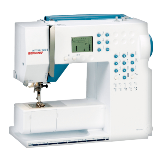
Page 7: Description
Description of the electronics The electronics of the BERNINA activa are basically contained in two modules (printed circuits), namely on the power L-print and the S-print (see block diagram). Power supply L-print The power L-print is mounted at the rear of the sewing machine. -
Page 8: Block Diagram
Block Diagram Power cirguit Command circuit Mains voltage Display Foot control Return-Button Sewing light Main motor Phototransistor and LED Bobbin winder Stepping motor stitch width Stepping motor stitch length Buttonhole sensor... - Page 9 8 L-Print Line Voltage!
-
Page 10: L-Print
S-Print Stitch length blue 4-pole Main motor white 2-pole L-Print white 8-pole Foot controler... -
Page 11: Diagnosting
10 Diagnostic instructions Warning Dangerous voltage levels ! Warning! Mains voltage (refer to L-print page 8). The sewing machine may only be connected to the mains supply when the L-Print cover is mounted. The switch part of the L-print and mains cable carry dangerous voltages. -
Page 12: Foot Control Unit
Test Programme activa 125/135/145 By pressing the «clear» button (clr) the machine can at any Starting the test programme given time be brought into the initial sate. Attention! Turn the machine off. • Place the service-panel on the machine. •... -
Page 13: P-Print (Positioning)
12 Test in basic servicing state contd. Test for the P-Print What is to be tested What to adjust Normal condition P-Print Initial state of service programme. In the L.C.R. needle position display a)By turning the handwheel, bring three digital signals can be read off. the needle in its lowest position. -
Page 14: Sewing-Off
Test Programmes Test LCD Liquid Crystal Display (Service Panel) What is to be tested What to adjust Normal condition LCD (Liquid Crystal Display) Select service programme LCD. All details show up on the screen and the LCD segment scrolls through all possibilities. -
Page 15: Test Buttonhole
14 Test Programmes Mechanical fine adjustment If the stitch formation is not absolutely closed after electronic compensation, a fine adjustment can be made with the balance regulating shaft 3. Procedure: Remove the balance knob 1. • Loosen screw 2. • Turn the balance regulating shaft 3 as required. -
Page 16: 3 Automatic Darning
Test Programmes Test No. 3 Automatic darning programme (Service Panel) What is to be tested What to adjust Normal condition Automatic darning programme Select service programme No. 3. The darning pattern must run parallel (Secondary test to buttonhole com- on both ends. Sketch!! pensation) Test No. -
Page 17: 6 Maximum Speed Regulation
16 Test Programmes Test No. 6 Maximum speed equalisation (Service Panel) What is to be tested What to adjust Normal condition Maximum speed equalisation Select service programme No. 6. Press foot control until «ok» appears (s.p.m. = stitch/minute) on the screen.The maximum speed The speed is set automatically appears on the screen. -
Page 18: 8 Pinning Position Of Both Stepping Motors
Test Programmes Test No. 8 Pinning position of stepping motors (Service Panel) What is to be tested What to adjust Normal condition Pinning position of step motors Select service programme No. 8. The step motors are activated to the step position for pinning. «P» appears on the screen. -
Page 19: 10 Displaying The Actual Speed
18 Test Programmes Test No.10 Speed of the machine (Service Panel) What is to be tested What to adjust Normal condition Actual speed of the machine Select programme No. 10. Press foot control. The speed is shown on the screen as a number x 10 (e.g. -
Page 20: 12 Start/Stop Function
Test Programmes Test No.12 Start/Stop function (Service Panel) Factory use only What is to be tested What to adjust Normal condition Permanent test of the machine Select service programme No. 12. Press the foot control. The machine will start and stop at a 7 second interval. -
Page 21: Testing Ribbon Cables
20 Test Programmes Test for the cable connection S-Print to L-Print What is to be tested What to adjust Normal condition Connection S-print to L-print Disconnect mains plug. Disconnect plugs from L-print and S-print. Visual inspection Inspect the cable for damage, short circuits, interruption. -
Page 22: Functional Inspection
Visual-, Functional-, Mechanical-, Sewing- and Technical-Inspection Visual Inspection: Mechanical inspection: Visual inspection of the whole machine Remove the covers Visual inspection of: Clean mechanical parts Bobbin holder Inspect the bevel gears for play/yesmming • Thread guide parts Inspect for play, or binding in: •... -
Page 23: 22 Removing Covers
22 Removing covers To do necessary adjustments the covers must be removed in the following order: Head cover: Remove the screw 5. Remove head cover. Removing L-print: Remove L-print cover screw 6. Swing out the cover and disconnect the cable connection Remove the complete L-print. -
Page 24: L-Print
Removing covers Remove the rear cover: Remove the 4 screws 7. Remove the rear cover. Note: For adjustment purposes refit the L-print. Front cover: Remove the balance knob 1. Remove the 4 screws 8. Feed dog in sewing position. Turn the hand- wheel until the driver rack is at its furthermost po-... -
Page 25: Cleaning
24 Cleaning Remove the covers and clean. Attention! Never use alcohol, petrol, spirits, or any other acid type of liquid. When cleaning covers it can happen that they will become electrostatically charged. To clean the covers, a liquid which is also used in the office equipment industry with an anti- static agent can be used. -
Page 26: Buttonhole Sensor
Replacing the S-print Disassembly: Assembly: 1) Remove the covers. 1) Fit the new S-Print in the front cover. 2) Remove the 4 screws 16. 2) Secure with 4 screws. 3) Exchange the S-Print. 3) Assemble the front cover. 4) Inspect the configuration (page 11). 5) Carry out a speed calibration (test No. - Page 27 26 Exchanging the L-Print Disassembly: 1) Remove screw 6 and disconnect the ribbon cable. 2) Remove the complete housing. 3) Remove the 4 screws 18 from the cover. 4) Remove the 2 screws 19.
-
Page 28: Main Motor
Exchanging the L-Print (contd.) 5) Remove the switch, transformer and L-Print from the housing. 6) Loosen all the electrical connection wires L- Print–transformer. Note the order of connections! 7) Exchange the L-Print. 8) If needed unsolder the mains cable bushes 21, main switch 22, voltage change-over switch 23 and exchan- Assembly: 1) Reconnect the transformer wires, being careful... -
Page 29: Stepping Motor Sb
28 Exchanging the stepping motor stitch width (SB) Disassembly: 5) Refit the balance knob. 1) Remove the balance knob. 6) Refit the L-Print housing. 2) Remove L-Print housing and covers. 7) Switch the machine in service programme on. 3) Remove the drive gear 26. 8) Select test No.8 (page 17). -
Page 30: Bobbin Winder Motor
Exchanging the bobbin winder motor Disassembly: 1) Remove all covers. 2) Remove the securing screw 42. 3) Exchange the bobbin winder motor. Assembly: 1) Mount the new bobbin winder motor and secure with screw. 2) Refit all covers. 3) Check the functions of bobbin winding (page 34). Exchanging the base shaft Disassembly: 3) Remove the feed-dog mechanism 43 by loosen the... -
Page 31: Hook Race Ring
30 Exchanging the hook race ring Disassembly: screw 53a. 1) Remove all covers. 5) Remove the 3 securing screws 55 and remove the hook 2) Using the special screwdriver 50 remove the stitch race ring 54. plate and surround. 6) Remove the thread guide plate and thread guide finger 3) Remove the hook race cover 51 by removing screws 4) Remove the hook 53 and hook driver by removing 7) Exchange the hook race ring. -
Page 32: Take-Up Lever
Exchanging the thread take-up lever Disassembly: 1) Remove all covers. 2) Remove the thread tension unit. 3) Remove the angular guide piece 60 along with screw 4) Disconnect the spring 62. 6) Loosen screw 66 in the balance piece 67. 5) Pull the needle bar guide piece 63 to the front, so that 7) Remove the crank from the balance piece –... -
Page 33: Main Shaft
32 Exchanging the main shaft and or the synchronisation disc Disassembly: 1) Remove all covers. 2) Loosen securing screws 73 + 74 from the balance piece. 3) Remove the drive belt. 4) Loosen belt tension of the main shaft. 5) Loosen the clamps 79 and remove. 6) Remove the complete main shaft to the right. -
Page 34: Adjustments
For all adjustments and in case no other needle size is given, always use a size Nm 80 needle. Before beginning any adjustments the needle must be tested for being straight! BERNINA uses needle system 130/705H TCN for all adjustments. Any service work being done on any machine, must be done using the original accessories that were delivered with the machine, or purchased later. -
Page 35: 34 Bobbin Winder Device
34 Bobbin winder device Standard: The thread should be wound evenly with pre-tension and the bobbin should be correctly filled. Correction for one-sided winding: Turn the adjustment screw 80 in or out as appropriate. Correcting the bobbin filling: The flip-flop spring should be in the third tooth of the relea- se lever. -
Page 36: Presser Foot Height
Presser foot height Standard: Lower the feed-dog. • Raise the lifter lever. • Check the height with 7.5 mm gauge 86. • Correction: Loosen screw 64 on the presser foot bar guide. • Place the presser foot on the gauge (7.5 mm). Keeping •... -
Page 37: Drive Position In The Hook Race
Position of the driver in the hook race Standard: The hook driver 102 should be 0.1– 0.15 mm behind the front edge of the hook race. Correction: Loosen the screw 103 of the driver shaft. • Push the complete driver 102 to the prescribed position. •... -
Page 38: Position Of Synchronisation Disc
Position of the synchronisation disc Rough adjustment after disassembling Standard: Position the balance piece with pin 92. • Fixation screw 77a on the synchronisation disc 77 must • be approx. at 30° above the horizontal position. Correction (Rough adjustment): Loosen the screw 77a. •... -
Page 39: Height Of The Feed-Dog
38 Feed-dog height Standard: At their highest point the tips of the feed-dog teeth should be 0.05mm higher at front than at the back. Example: Front 0.95 mm, back 0.90 mm • Front 1.00 mm, back 0.90 mm • Front 1.00 mm, back 0.95 mm •... -
Page 40: Thread Guide Plate
Thread guide plate Standard: The distance of the thread guide plate should be 0,3 to 0,5 mm from the right edge and 0,7 mm to the hook Thread guide plate race. Thread positioning plate Correction: The thread guide plate should be in a position, that Hook race ring distances are within the tollerances. -
Page 41: Position Of Hook /Driver
40 Position of hook in relation to the needle Standard: Pin the balance piece, stepping motor zig-zag and • the hook drive crank. The hook point must now be flush with the right hand edge • of the needle (see encircled part of diagram). Correction: Pin the balance piece, stepping motor zig-zag and the •... -
Page 42: Feed-Dog Synchronisation
Feed-dog synchronisation (feed-dog lift and advance) Standard: Pin the balance piece. • The base shaft must now be in a position, where the • marker pin on the drive gear is in a front horizontal position (09:00 hours) to the shaft. Correction: As both lifter and advance eccentrics are pressed into the shaft, continue as follows:... -
Page 43: Knee Lifter Unit (Accessory)
42 Basic adjustment to the knee lifter lever (Available as a special accessory) Standard: The end of the knee lifter should be vertical under the • right edge of the LCD. Correction: Loosen the screw 109 of the feed-dog drop unit. •... -
Page 44: Upper Thread Tension
Adjustment of upper thread tension with a weight Standard: must now move down slowly. Test thread Mettler white (BW Ne 60/2 resp. NM 43.1/2). • Thread the machine including the take-up lever. Correction: • Bring the take-up lever/needle bar to the highest positi- See correction basic adjustment. -
Page 45: Tension Release Lever
Adjust the distance between the pres- sure disc to 0.3mm with the screw (122) Thread regulator spring Checking the tension: 12 g –15 g (use BERNINA Tension spring 006 038 5000) Correction tension: By turning screw 113 clockwise or anti-clockwise, the tension will beco- me more or less. -
Page 46: Oiling And Lubrication
Oiling and Lubrication In the lubrication plan, parts that have to be lubricated after a certain time are marked with the corresponding lubricant to be used. -
Page 47: Sewing-Off
Sewing-off The sewing off operation is used as a control method to 7) Buttonhole inspect whether the machine has reached the required Standard buttonhole standards after adjustments have been carried out and that is the stitch formation symmetrical • it is functioning correctly. are the beads equal •... - Page 48 © Copyright 2001 by Fritz Gegauf Ltd, Steckborn...