
Related Manuals for Cobra Fortis 14L


Summary of Contents for Cobra Fortis 14L
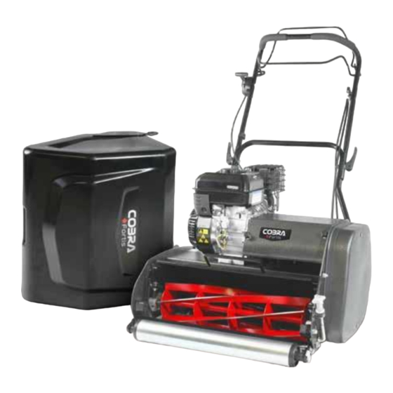
- Page 1 MODELS: Fortis 14L, 17B, 20B, 25B (RMC14, 17, 20, 25) COBRA LAWN MOWER OWNER’S MANUAL Cobra Garden Machinery Henton and Chattell Ltd., London Road, Nottingham NG2 3HW UK www.cobragarden.co.uk...
- Page 2 WARNING: For your own safety please read this manual before attempting to operate your new unit. Failure to follow instructions can result in serious personal injury. Spend a few moments to familiarise yourself with your mower before each use. Keep this manual in a safe place, so that the information is available at all times.
-
Page 3: Table Of Contents
CONTENTS SYMBOLS MARKED ON THE PRODUCT……………………………4 SECTION 1 GENERAL SAFETY RULES…………………………………………… 5 SECTION 2 PARTS DESCRIPTION………………………………..…………….…. 9 SECTION 3 ASSEMBLY…………………………………………………………….… SECTION 4 SECTION 5 PREPARING FOR USE…………………………………………….…... OPERATION INSTRUCTIONS……………………………………..…. 11 SECTION 6 SAFETY CHECKS, SERVICE & MAINTENANCE……………..……. SECTION 7 SECTION 8 CHANGING THE CARTRIDGE CASSETTE..……………………..…... -
Page 4: Symbols Marked On The Product
1.SYMBOLS MARKED ON THE PRODUCT WARNING: For your own safety please read this manual before attempting to operate your new mower. Failure to follow instructions can result in serious personal injury. Spend a few moments to familiarise yourself with your mower before each use. Symbols and Warnings Read the instruction handbook and follow all warning and safety instructions. -
Page 5: General Safety Rules
Warning: Always use correct tools and original spare parts. KEEP HANDS AND FEET AWAY. WARNING: Keep the safety signs clear and visible on the equipment. Replace the safety signs if they are missing or illegible. 2. GENERAL SAFETY RULES WARNING: When using petrol tools, basic safety precautions, including the following, should always be followed to reduce the risk of serious personal injury and/or damage to the unit. - Page 6 the engine is hot. If petrol is spilled, do not attempt to start the engine, but move the machine away from the area of spillage and avoid creating any source of ignition until petrol vapours have dissipated. Replace all fuel tank and container caps securely. 4.
- Page 7 21. Stop the engine and disconnect the spark plug wire, make sure that all moving parts have come to a complete stop and, where a key is fitted remove the key, make sure engine is completely cooled. - Whenever you leave the lawn mower. - Before refueling.
- Page 8 17. Only use the recommended blades and spare parts by the manufacturer. The use of non-genuine parts can damage the machine and injure the operators. Keep the lawnmower in good working condition. 18. If the blade stopping device doesn’t work, please contact service centre for help. Warning: Do not touch a rotating blade.
-
Page 9: Parts Description
PARTS DESCRIPTIONS Notice: the illustrations may vary from your present model 1. Throttle lever 5. Lower handle 9. Grass box collector 13. Engine 2. Upper handle 6. Release for handle 10. Front roller Switch 3. Drive clutch lever 7. Fuel cap 11. -
Page 10: Assembly
4. ASSEMBLY Unpacking: Remove the mower, fixings, tools and other items from the carton. Warning: The mower is heavy. Take care when lifting and handling. Warning: Ensure that cables are not pinched or damaged whilst removing from the package. Assembly of handlebar: 1. - Page 11 Fitting the throttle cable: Follow the steps below to install the throttle control cable to the engine. 1. Remove the air filter cover (Fig. 5) 2. Remove the air filter (Fig. 6) 3. Remove 2 screws from the air filter base. Refer to red circles in Fig. 7 4.
- Page 12 5. When mounting up the throttle cable there is two options, - Option 1- Z shape cable to be mounted in hole on throttle linkage. Refer to red circle in Fig. - Option 2 – Cut Z shape off throttle cable and mount into linkage slot nut. Refer to red circle in Fig.
-
Page 13: Preparing For Use
2. Fill the oil to the top of the crankcase with SAE 30 Engine Oil. Refer to Fig. 13 - Refer to the appropriate diagram below. - Fill the oil between upper and lower limit. Fig. 13 Loncin Engine – Fortis 14L Fig. 13 Briggs and Stratton Engine Fortis 17B, 20B and 20B... -
Page 14: Operation Instructions
engine is hot. If petrol is spilled, do not attempt to start the engine, but move the machine away from the area of spillage and avoid creating any source of ignition until petrol vapors have dissipated. Replace all fuel tanks and container caps securely. Before tipping the lawn mower to maintain the blade or drain oil, remove fuel from tank. - Page 15 Fig. 15 – Select the ‘ON’ position on the engine switch. Fig. 17 – Move the throttle control about 1/3 of the way toward the ‘FAST’ position. Fig. 18 – Move the fuel valve to ‘ON’ to allow the fuel to flow to the carburetor. Fig.
- Page 16 Fig. 20 - Pull the starter grip lightly until you feel resistance, then pull quickly. Return the starter grip gently. Repeat until the engine starts. Adjust the choke as required to avoid the carburetor becoming flooded (Fig.19). Once the engine has started, gradually move the ‘CLOSE’ choke lever to ‘OPEN’ as the engine warms up.
- Page 17 Fig. 25 - Pull the starter grip lightly until you feel resistance, then pull quickly. Return the starter grip gently. Repeat until the engine starts. Adjust the choke as required to avoid the carburetor becoming flooded (Fig.22). Once the engine has started, gradually move the ‘CLOSE’ choke lever to ‘OPEN’ as the engine warms up.
- Page 18 Lawnmowing Procedure Preparation Warning: Check the area to be mowed thoroughly to remove debris from the lawn which may be projected from the mower. Stones, twigs, wire, and other debris will damage the lawnmower. Operators must be familiar with the controls before taking control of the lawnmower. Bystanders and animals should be a safe distance away from the mowing area.
- Page 19 How to Stop the Lawnmower Warning: The blade and drive will not stop immediately. Fig. 26 In the case of an emergency ‘STOP’ release both the cutting cylinder and drive control levers. The engine will continue to run but the cutting cylinder and power drive will stop. For a planned stop: 1.
- Page 20 3. To remove the catcher, disengage the blade driver lever and stop the engine. 4. Lift the catcher from the top section and empty. Changing the Height of Cut Warning: Switch off the engine and disconnect the spark plug connector before making any adjustments of maintenance.
- Page 21 5. Re-tighten bolts. Fig. 32 & Fig. 35. 6. Test the cutting action with paper as previously described. Should the paper not cut satisfactorily, the cylinder may need to be sharpened. Contact your local Cobra dealer. Fig. 32 Fig. 33 Fig.
- Page 22 Cylinder Blade Drive Belt Control Adjustment Warning: Switch off the engine and disconnect the spark plug connector before making any adjustments of maintenance. Following the adjustment to the blade settings, or as a regular maintenance procedure, the adjustment control should be checked and adjusted from time to time. 1.
- Page 23 Handle Position Adjustment Fig. 42 Fig. 43 Fig. 44 The height of the handles may be adjusted to suit the operator. At the lower section of the handle, the securing bolts should be loosened to adjust the angle of the handles. The side cover should removed to access the two bolts on this side. Once the required height is set, secure the bolts on each side.
-
Page 24: Safety Checks, Service & Maintenance
Do not hose or pressure washer the lawnmower. The lawnmower must serviced regularly. For normal homeowner use, the lawnmower should be serviced by a Cobra service dealer annually, however where the lawnmower is used more frequently ensure the lawnmower is serviced more regularly. - Page 25 Removing and Fitting the Fortis Cartridge Fig. 46 Fig. 47 Fig. 48 Fig. 49 Fig. 50 Fig. 51 Removing the Cartridge 1. Remove the side cover, unscrewing the 2 bolts highlighted in the red circle. Fig.46 2. On the other side of the mower, remove the bolts securing the cartridge which is highlighted in fig.
-
Page 26: Fault Diagnosis & Remedy
The cylinder to bottom blade gap Check and adjust the gap. Check and is not ‘on-cut’ across the whole consistent. Some sharpen the cylinder if necessary. Damaged – see a Cobra dealer blade. The blade system is areas are not cut damaged. correctly. - Page 27 Any damage that occurs from the use of non-genuine Cobra parts will not be covered. We reserve the right to reject any claim where the purchase cannot be verified or when it is clear that the product was not maintained properly.
-
Page 28: Conformity
EN ISO 14982 Authorized Signature/Date/ Place: Peter J. Chaloner 26/3/2023 Title of Signatory: Managing Director Name and address of the Cobra Garden Machinery, Henton & Chattell Ltd, London Road, person authorized to Nottingham compile the technical file NG2 3HW UK...