
Related Manuals for Emerson ControlWave


Summary of Contents for Emerson ControlWave
- Page 1 Instruction Manual Part Number D301385X012 Document: CI-ControlWave EXP August 2015 ControlWave ® I/O Expansion Rack Remote Automation Solutions www.EmersonProcess.com/Remote...
- Page 2 These instructions may not cover all details or variations in equipment or cover every possible situation to be met in connection with installation, operation or maintenance. Should problems arise that are not covered sufficiently in the text, the purchaser is advised to contact Emerson Process Management, Remote Automation Solutions for further information.
-
Page 3: Table Of Contents
ControlWave I/O Expansion Rack Instruction Manual Contents Chapter 1 – Introduction Scope of the Manual ......................... 1-2 Physical Description ........................1-2 Housings ........................... 1-3 CPU Module ..........................1-5 Power Supply/Sequencer Module (PSSM) ................1-6 ... - Page 4 ControlWave I/O Expansion Rack Instruction Manual Chapter 4 – Operation Powering Up/Powering Down the ControlWave I/O Expansion Rack ........4-1 Communicating with the ControlWave I/O Expansion Rack ............. 4-1 4.2.1 Default Comm Port Settings ..................4-1 ...
-
Page 5: Chapter 1 - Introduction
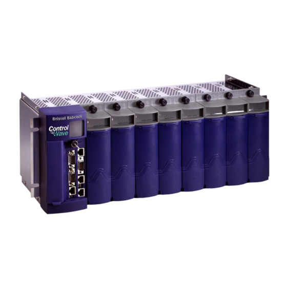
The ControlWave I/O expansion rack was designed with an emphasis on providing high performance with low power consumption, scalability, and modularity. You can configure the ControlWave I/O expansion rack as a slave to a ControlWave Process Automation Controller (CWPAC), ControlWave Redundant Controller (CWRED), or a ControlWave Redundant I/O Switch Unit (CWRED I/O). -
Page 6: Scope Of The Manual
Troubleshooting 1.2 Physical Description Each ControlWave has a printed circuit board (PCB) backplane mounted in a stainless steel housing, a Power Supply/Sequencer Module (PSSM), a CPU module which may include an optional Secondary Communication Board (SCB) and—depending on the backplane and housing size—up to eight I/O modules. -
Page 7: Housings
One or more I/O modules (see Section 1.6 and Chapter 3) 1.3 Housings ControlWave housings are stainless steel designed for panel/wall- mounting or for some versions, for mounting in a 19-inch equipment rack. They contain the printed circuit board (PCB) backplane into which you connect the PSSM, the CPU module, and any I/O modules. - Page 8 ControlWave I/O Expansion Rack Instruction Manual Figure 1-2. ControlWave I/O Expansion Rack Housing Options Introduction Revised Aug-2015...
-
Page 9: Cpu Module
ControlWave I/O Expansion Rack Instruction Manual 1.4 CPU Module Note : The ControlWave I/O Expansion Rack CPU does not accept a downloadable ControlWave project (software application), it only holds I/O modules. A separate ControlWave Process Automation Controller runs the ControlWave project which must reference the I/O points in the ControlWave I/O Expansion Rack. -
Page 10: Power Supply/Sequencer Module (Pssm)
Chapter 2 includes instructions for installing and configuring the PSSM. 1.6 I/O Modules The ControlWave I/O expansion rack supports analog input, analog output, digital input, digital output, universal digital input, isolated RTD, and isolated low level analog (thermocouple and mv) input modules for either local or remote field device wiring termination. -
Page 11: Secure Gateway
MOXA EDR‐810, the Hirschman Eagle One, or the Phoenix mGuard rs4000 (or equivalents). An example of how to install one of these devices to the RTU can be found in the Emerson Remote Automation Solutions MOXA® Industrial Secure Router Installation Guide (part number D301766X012). - Page 12 This page is intentionally left blank...
-
Page 13: Chapter 2 - Installation
2.1 Site Considerations When choosing an installation site, check all clearances. Ensure that the ControlWave I/O expansion rack is accessible for wiring and service. To ensure safe use of this product, please review and follow the Caution instructions in the following supplemental documentation: ... -
Page 14: Class I, Div 2 Installation Considerations
2.1.1 Class I, Div 2 Installation Considerations Placement of the ControlWave in Class 1, Division 2 (Group A, B, C, and Caution D) hazardous locations requires that you select an appropriate enclosure that meets NEMA Type 3X or 4X specifications. -
Page 15: Installation Overview
Setting flash memory parameters in the I/O expansion rack(s). Creating an application-specific control strategy (ControlWave project) for the ControlWave host that references the I/O in the I/O expansion rack. Downloading the application-specific ControlWave project into the ControlWave host controller. -
Page 16: Unpacking Components
ControlWave I/O Expansion Rack Instruction Manual : Steps 2 through 6 require that you install and use ControlWave Note Designer and OpenBSI software on your PC. This manual focuses on hardware installation and preparation. Software installation and configuration is beyond the scope of this manual. -
Page 17: Color Coding Of Slot Connectors
ControlWave I/O Expansion Rack Instruction Manual Notes: There are many different types of I/O modules available. Chapter 3 contains detailed instructions on each I/O module. Universal Digital Input (UDI) modules can only reside in the first four I/O slots. One or more bezel assemblies; each bezel covers two I/O modules. - Page 18 ControlWave I/O Expansion Rack Instruction Manual Figure 2-3. PSSM Installed in ControlWaveEXP Slot #1 Figure 2-4. PSSM & CPU (with SCB) Installed in Slot #1 & #2 (Respectively) Installation Revised Aug-2015...
-
Page 19: Mounting The Housing
See Figure 2-6 for mounting hole patterns for a 4- I/O unit. You can install a ControlWave I/O expansion rack equipped with an 8- I/O module housing in a 19-inch equipment rack, a panel or a wall. - Page 20 ControlWave I/O Expansion Rack Instruction Manual Figure 2-5. 8-I/O Module ControlWave I/O Rack - Mounting Diagram (dimensions in inches) Installation Revised Aug-2015...
- Page 21 ControlWave I/O Expansion Rack Instruction Manual Figure 2-6. 4-I/O Module ControlWave - Mounting Diagram (dimensions in inches) Revised Aug-2015 Installation...
- Page 22 ControlWave I/O Expansion Rack Instruction Manual Figure 2-7. 4-I/O Module ControlWave - Mounting Diagram 2-10 Installation Revised Aug-2015...
-
Page 23: Grounding The Housing
Once you install the housing, you must run a ground wire between the housing ground lug and a known good earth ground. When you install the various ControlWave modules into the housing and secure them using the captured panel fasteners, this automatically connects them to chassis ground. - Page 24 ControlWave enters a “watchdog” condition in which the CPU cannot control your process. This occurs on power-up before the ControlWave project starts, if the unit is reset, if the ControlWave project “crashes” or if the system loses power. See Section 2.3.7.
-
Page 25: Pssm Installation Overview
ControlWave Redundancy Switcher detects a watchdog failure in the other ControlWave I/O rack, the redundancy control input sends signals to this ControlWave I/O rack that it must take control. For more information on how this works, see the ControlWave Redundancy Setup Guide (D5123) and the ControlWave Redundant I/O and Control Switch Unit Manual (CI-ControlWave REDI/O). -
Page 26: Setting Jumpers
In a ControlWave Redundant Controller or In a ControlWave Controller that is part of a redundant pair or In a ControlWave I/O Expansion Rack that is part of a redundant pair. Enables the 12V monitor. This is the default. When enabled, the PSSM reports a failure when voltage falls below 12V and lights the PWR Down LED to indicate the failure. - Page 27 ControlWave I/O Expansion Rack Instruction Manual screws Figure 2-9.Removing the Protective Case from the PSSM Revised Aug-2015 Installation 2-15...
-
Page 28: General Wiring Guidelines
ControlWave I/O Expansion Rack Instruction Manual Figure 2-10. Jumper Locations Make the necessary adjustments to the jumpers according to Table 2-1. When finished, re-attach the case by first aligning the protective case with the screw holes, then inserting and tightening each screw. -
Page 29: Wiring A Bulk Dc Power Supply To The Pssm
TB1 and TB2 (or TB3) to the PSSM until after you install, wire, and configure the CPU module. Follow the instructions in Section 2.3.4 when wiring connections. The ControlWave operates from +22.2 Vdc to +30.0 Vdc (with a Operating nominal +24Vdc input source). - Page 30 6 LLAI Module See table (no surge current) So, for example, if you have a ControlWave I/O rack with a 16AI module, an 8AO module, and a 32DI module, the maximum current draw is 1A for the CPU plus 2A for the 16AI module plus 1A for the 8AO module and 1A for the 32DI module, for a total of 5A.
- Page 31 ControlWave I/O Expansion Rack Instruction Manual Table 2-2. Steady State Current Draw for Bulk Power Supplies Component(s) System Current Field Current draw for Notes draw for 24Vdc 24Vdc Power Supply Power Supply CPU (with Ethernet), 290 mA Not applicable PSSM and backplane...
-
Page 32: Hot-Swapping A Power Supply
ControlWave I/O Expansion Rack Instruction Manual 2.3.6 Hot-swapping a Power Supply DO NOT ATTEMPT hot swapping in a Class I, Division 2 WARNING hazardous location. Each power supply has a Power Good indication LED (see Chapter 5). If this light goes out while the power supply is on, the power supply’s output voltage is out of specification. -
Page 33: Wiring An External Alarm Or Annunciator To The Watchdog Connector And Wiring The Redundancy Control Input (Optional)
ControlWave I/O Expansion Rack Instruction Manual 2.3.7 Wiring an External Alarm or Annunciator to the Watchdog Connector and Wiring the Redundancy Control Input (OPTIONAL) At this time you can also connect power and watchdog wiring. Caution However; for safety reasons and to prevent accidental damage to the... - Page 34 ControlWave I/O Expansion Rack Instruction Manual When using a pair of ControlWave I/O expansion racks, each with a PSSM, and a ControlWave Redundant I/O and Communications Switch Unit (the redundant I/O switcher), the choice of which unit is “online” and which unit is “backup” is determined by redundancy control line...
-
Page 35: Wiring Digital Inputs To Indicate Power Supply Failure
ControlWave I/O Expansion Rack Instruction Manual Figure 2-16. Location of TB2 on ControlWave I/O Switcher 2.3.8 Wiring Digital Inputs to indicate Power Supply Failure Each power supply on the PSSM drives a solid state relay contact closed during normal operation. In a failure, this contact opens. You can optionally wire the contact to a digital input (either externally or internally sourced) to provide indication of a power supply failure. -
Page 36: Pssm Specifications
ControlWave I/O Expansion Rack Instruction Manual 2.3.9 PSSM Specifications Table 2-4. PSSM Specifications Redundant Power Supply Sequencer Module 22.2 to 30V DC (24V input supply, Input Range: nominal) Shutdown occurs at 22.2 nominal for 24V input supply systems, respectively. Operating: -40 to 70 o C... -
Page 37: Cpu Module
ControlWave I/O Expansion Rack Instruction Manual 2.4 CPU Module The CPU module, which controls the ControlWave I/O Expansion Rack and handles memory and communication functions, can only be installed in Slot #2 of the backplane. Identify the carton holding the CPU module and remove it from that carton. -
Page 38: Setting Dip Switches On The Cpu Module
ControlWave I/O Expansion Rack Instruction Manual Figure 2-18. ControlWave I/O Expansion Rack CPU Module (with SCB) 2.4.1 Setting DIP Switches on the CPU Module Before you install the CPU module, you must determine the settings for its DIP switches. Refer to Figure 2-17 for the location of the DIP switch banks on the CPU board itself. - Page 39 OFF (Redundancy Enabled. This ControlWave is one of two in a redundant pair) Unit A / Unit B Specifies whether this ControlWave is the “A” or “B” unit in a redundant pair. Values are: ON (“A” unit in the redundant pair; factory default) OFF (“B”...
- Page 40 ControlWave I/O Expansion Rack Instruction Manual Table 2-6. CPU Board Switch SW3 SW3 Setting Function Mode Not currently used. System Enables / disables remote system firmware upgrade via Firmware load System Firmware Downloader: control ON (disables remote system firmware upgrade) OFF (enables remote system firmware upgrade;...
-
Page 41: Connections To Rs-232 Serial Port(S)
RS-232 port. RS-232 COM ports are assigned names based on their location in the RS-232 COM ControlWave I/O Expansion Rack. The CPU board has two RS-232 Port Names and ports (COM1 and COM2). See Table 2-9. - Page 42 You can purchase a null modem cable using part number 392843- 01-3. : You can configure the ControlWave as either a master or slave Note node on a BSAP network. Figure 2-20 illustrates the CPU module’s male 9-pin D-type connector.
- Page 43 Clear to Send Input Ring Indicator Use the “null modem” cable for full-duplex (PPP protocol) communications when connecting a ControlWave to a PC. (See top part of Figure 2-21.) Figure 2-21. Full-duplex and Half-duplex Cable Use the half-duplex cable (shown in the bottom part of Figure 2-21) when connecting the ControlWave to another ControlWave series unit (again, with the exception of the CW_10/30/35 units).
-
Page 44: Connections To Rs-485 Serial Port On The Secondary Communication Board (Scb)
ControlWave I/O Expansion Rack Instruction Manual 2.4.3 Connections to RS-485 Serial Port on the Secondary Communication Board (SCB) The RS-485 port supports local network communications to multiple nodes up to 4000 feet away. If you purchased your CPU module with a secondary communication board (SCB) you have a single RS-485 port. - Page 45 Wire the master node to one end of the RS-485 cable run using a 24-gauge paired conductor cable (such as a Belden 9843). : ControlWave only supports half-duplex RS-485 networks. Note Table 2-14. RS-485 Network Connections...
-
Page 46: Connections To Ethernet Port(S) On The Cpu Module
ControlWave I/O Expansion Rack Instruction Manual 2.4.4 Connections to Ethernet Port(s) on the CPU Module The ControlWave can support either one or three Ethernet ports. These use a 10/100Base-T RJ-45 modular connector that provides a shielded twisted pair interface to an Ethernet hub. Two LEDs per port provide transmit and receive status indications: Table 2-15 shows port assignments for the Ethernet ports. -
Page 47: Bezels
The factory ships a version of the bezel appropriate to the options you ordered. You should install the bezel whenever the ControlWave is operational. The bezel includes a door you can open to access the PSSM and CPU modules. If necessary, you can remove the bezel for maintenance procedures. - Page 48 ControlWave I/O Expansion Rack Instruction Manual To remove the bezel, gently grasp its sides and pull out and away from the chassis. Figure 2-26. Bezel Assembly (for CPU Module without SCB) 2-36 Installation Revised Aug-2015...
-
Page 49: Chapter 3 - I/O Modules
3.10 Isolated Thermocouple Module ............. 3-40 Installation Installing any I/O module in the ControlWave I/O expansion rack involves the same basic steps: Remove the I/O module from the shipping carton. I/O modules include a removable terminal housing assembly. This assembly has a door that swings downward to provide access to the unit’s terminal... - Page 50 Figure 3-1. Terminal Housing Assembly Removal Using a PC running ControlWave Designer and OpenBSI software, configure the ControlWave project running in the host ControlWave controller to reference the new I/O modules in the I/O rack, and download the revised ControlWave project into the host controller.
-
Page 51: Module Placement
Interrupt driven I/O modules, such as the Universal Digital Input Note: (UDI) cannot reside in slots 7 through 10 of the 10 slot housing. Figure 3-2 shows slot assignments for an 8 I/O ControlWave I/O expansion rack. Revised Aug-2015 I/O Modules... -
Page 52: Status Leds
ControlWave I/O Expansion Rack Instruction Manual Figure 3-2. ControlWave Chassis Slot Assignments (with/without bezel shown) 3.2 Status LEDs Most of the I/O modules include one or more light emitting diodes (LEDs) to provide diagnostic or status indications. See Chapter 5 for information on the different LEDs. -
Page 53: Local Termination
DIN-rail mounted terminal assembly and then to field devices). ControlWave I/O modules use compression-type terminals that accommodate up to #14 AWG wire. Insert the wire’s bared end (approx. ¼” max) into the clamp beneath the screw and secure the wire. To prevent shorts, ensure that no bare wire is exposed. -
Page 54: Remote Termination
ControlWave I/O Expansion Rack Instruction Manual 3.3.2 Remote Termination For I/O modules that support remote terminations, install cables between the module’s remote headers and the remote DIN-rail mounted terminal block assemblies (see Figure 3-4). Install field wiring between the DIN-rail mounted terminal bock assembly and field devices (see the wiring diagrams associated with each I/O module description). - Page 55 ControlWave I/O Expansion Rack Instruction Manual Figure 3-4. I/O Module (Remote Termination) Wire Routing Revised Aug-2015 I/O Modules...
-
Page 56: Digital Input (Di) Modules
+21Vdc power supply (dry contacts). Note: Early versions of ControlWave DI modules required you to specify either internal or external sourcing for all DIs when you ordered the module; now you can set this yourself using jumpers on a per DI basis. - Page 57 ControlWave I/O Expansion Rack Instruction Manual for use in dry contact applications contain a +21 Vdc isolated power supply powered through an output of the hot swap circuitry which receives power originating on the backplane. Setting Jumpers You must set configuration jumpers for each DI. according to Table 3- 3.
- Page 58 ControlWave I/O Expansion Rack Instruction Manual Figure 3-6. DI Module - Local Terminal Block Assembly Assignments Figure 3-7. Internally Sourced DI Module - Wiring Diagram Figure 3-8. Externally Powered DI Module - Wiring Diagram 3-10 I/O Modules Revised Aug-2015...
- Page 59 Figure 3-9. Remote DIN-Rail Mountable Terminal Block Assembly Assignments Software Configuration To use data from any ControlWave DI module in the rack you must use ControlWave Designer’s I/O Configurator to modify the ControlWave project in the host to add an ER_DI32 board and then configure it.
- Page 60 ControlWave I/O Expansion Rack Instruction Manual Figure 3-10. Remote DIN-Rail Mountable Terminal Block Assembly Assignments for Relay Isolated 120Vac DI Operation 3-12 I/O Modules Revised Aug-2015...
-
Page 61: Digital Output (Do) Modules
ControlWave I/O Expansion Rack Instruction Manual Digital Output (DO) Modules DO modules provide 32 or 16 DOs to control signaling functions. DO modules consist of a DO PCB with either a terminal block assembly (for local termination) or a header block assembly (for remote termination). - Page 62 ControlWave I/O Expansion Rack Instruction Manual operating in online mode monitors the DO values of its standby counterpart in order to verify that standby DO values are consistent should a failover occur. Depending upon software configuration settings; a failover can be prevented if they are inconsistent. A standard DO module used in a redundant system does not perform this monitoring;...
- Page 63 ControlWave I/O Expansion Rack Instruction Manual Figure 3-12. Open Source Isolated DO Module - Wiring Diagram Revised Aug-2015 I/O Modules 3-15...
- Page 64 ControlWave I/O Expansion Rack Instruction Manual FUSES: F0 to F7: 1A, F+: 2A Figure 3-13. Remote DIN-Rail Mountable Terminal Block Assembly for Open Source Isolated DO Operation Assignments 3-16 I/O Modules Revised Aug-2015...
- Page 65 ControlWave I/O Expansion Rack Instruction Manual Figure 3-14. Remote DIN-Rail Mountable Terminal Block Assembly Assignments for Relay Isolated 24Vdc DO Operation Revised Aug-2015 I/O Modules 3-17...
- Page 66 ControlWave I/O Expansion Rack Instruction Manual Software Configuration To use data from any ControlWave DO module in the rack you must use ControlWave Designer’s I/O Configurator to modify the ControlWave project in the host controller to add an ER_DO32 board and then configure it.
- Page 67 ControlWave I/O Expansion Rack Instruction Manual failure in the associated device as an error; failover is inhibited. When you set this variable to TRUE, the system treats a DO readback failure in the associated device as a warning that does not prevent a failover, and the only reporting is via the _RDN_IO_x_ERR variables and LEDs discussed, above.
-
Page 68: Analog Input (Ai) Modules
Surge suppression and signal conditioning. Cable Shields Connect cable shields associated with AI wiring to the ControlWave housing ground. Multiple shield terminations require that you supply a copper ground bus and connect it to the housing’s ground lug (using up to a #4 AWG wire size). - Page 69 ControlWave I/O Expansion Rack Instruction Manual Table 3-8. Analog Input Module Configurations Part Number Number of AIs Termination Notes Connector 4-20 mA 396352-01-4 Local 4-20 mA 396352-03-0 Local 4-20 mA 396352-11-1 Remote 4-20 mA 396352-13-8 Remote 396352-12-0 Remote 1-5 Vdc Wiring the Module Figure 3-18 shows terminal assignments for a locally terminated AI module;...
- Page 70 Figure 3-17. Externally Powered Isolated 1-5 Volt AI - Wiring Diagram Figure 3-18. Local AI Module Terminal Blocks Assembly Assignments Software Configuration To use data from any ControlWave AI module in the rack you must use ControlWave Designer’s I/O Configurator to modify the ControlWave project in the host controller to add an ER_AI16 board and then configure it.
- Page 71 ControlWave I/O Expansion Rack Instruction Manual FUSES: F0, F2, F4, F6: 1/8A for 4-20 mA AI Figure 3-19. Remote DIN-Rail Mountable Terminal Block Assembly Assignments Operation Revised Aug-2015 I/O Modules 3-23...
- Page 72 ControlWave I/O Expansion Rack Instruction Manual FUSES: F0, F2, F4, F6: 1/8A for 1-5V AI Figure 3-20. Remote DIN-Rail Mountable Terminal Block Assembly Assignments Operation 3-24 I/O Modules Revised Aug-2015...
-
Page 73: Analog Output (Ao) Modules
ControlWave I/O Expansion Rack Instruction Manual Analog Output (AO) Modules AO modules support eight 4–20 mA analog outputs. AO modules consist of an AO PCB (with a daughter board when configured for read- back) an LED board, a terminal housing assembly, as well as I/O assembly and mounting hardware. - Page 74 ControlWave I/O Expansion Rack Instruction Manual Table 3-10. Analog Output Module Configurations Part Number Number of Termination Notes Connector 4-20mA 396353-01-0 local 4-20mA 396353-11-8 remote 396353-20-7 remote 4-20mA AO Readback on this module Wiring the Module Figure 3-21 shows field wiring assignments for a locally terminated AO module.
- Page 75 ControlWave I/O Expansion Rack Instruction Manual FUSES: F0, F2, F4, F6: 1/8A for AO 4-20mA Figure 3-22. Remote DIN-Rail Mountable Terminal Block Assembly Assignments Operation Revised Aug-2015 I/O Modules 3-27...
- Page 76 ControlWave I/O Expansion Rack Instruction Manual Figure 3-23. 4-20mA Current Loop AO - Wiring Diagrams Software Configuration To use data from any ControlWave AO module in the rack you must use ControlWave Designer’s I/O Configurator to modify the ControlWave project in the host controller to add an ER_AO8 board and then configure it.
- Page 77 ControlWave I/O Expansion Rack Instruction Manual unit is rebooted, either through a sideload, forced redundant switchover, or power-down and restart, or you remove and replace the board (hot card replacement). Each of these operations momentarily turns the FAIL LED to GREEN (and the associated _ERR error...
-
Page 78: Universal Digital Input (Udi) Modules
ControlWave I/O Expansion Rack Instruction Manual Universal Digital Input (UDI) Modules Universal Digital Input (UDI) modules include six inputs which you can individually configure as high speed counters or polled inputs. UDI modules consist of a UDI PCB, either a terminal board assembly... - Page 79 ControlWave I/O Expansion Rack Instruction Manual Configurations The UDI module (general part number 396362-XX-X) has the following configurations: Table 3-12. UDI Module Configurations Part Number Number of UDIs Termination Connector 396362-02-8 local 396362-12-5 remote Setting Jumpers Each input has a jumper to enable/disable debounce. Enabling debounce activates filters that reduce spurious pulses caused by relay contact bounce.
- Page 80 ControlWave I/O Expansion Rack Instruction Manual Table 3-13. Jumper Assignments: UDI Module Jumper Purpose Description Configures UDI1 Pins 1-2 installed = Enable Debounce (Factory default). A change of state on both the SET and RST (reset) field inputs is required to accumulate counts.
- Page 81 ControlWave I/O Expansion Rack Instruction Manual Terminal Block Assembly Assignments FIELD Field CIRCUITRY UDI Operation HSCSET HSCCOM +HSCSET1 +HSCSET2 HSCCOM1 HSCCOM2 +HSCRST1 +HSCRST2 HSCRST +HSCSET3 +HSCSET4 HSCCOM3 HSCCOM4 ‘A’ +HSCRST3 +HSCRST4 +HSCSET5 +HSCSET6 Relay Contact HSCCOM5 HSCCOM6 +HSCRST5 +HSCRST6 FIELD...
- Page 82 ControlWave I/O Expansion Rack Instruction Manual Cable Assembly (One of 2 Cables) End of cable that interfaces with Remote UDI Module’s Header Block Assembly End of cable that interfaces with Remote UDI Module’s DIN-Rail Mountable Terminal Block Assembly From P1...
- Page 83 ControlWave I/O Expansion Rack Instruction Manual Software Configuration To use data from any ControlWave UDI module in the rack you must use ControlWave Designer’s I/O Configurator to modify the ControlWave project in the host controller to add an ER_HSC12 board and then configure it.
-
Page 84: Isolated Resistance Temperature Device (Rtd) Input Module
ControlWave I/O Expansion Rack Instruction Manual Isolated Resistance Temperature Device (RTD) Input Module RTD Input modules provide a total of four inputs. Firmware detects the RTD type (2-, 3- or 4 wire) via the installation of jumper wires on the terminal block for 2-wire and 3-wire RTDs (see Figure 3-30). - Page 85 ControlWave I/O Expansion Rack Instruction Manual Table 3-16. Jumper Assignments: Non-isolated HSC Module Jumper Purpose Description Enables/disables LEDs on Pins 1-2 installed = Enable LEDs (Factory default). module Pins 2-3 installed = Disable LEDs Wiring the Module Figure 3-31 shows field wiring assignments for locally terminated isolated RTD modules.
- Page 86 ControlWave I/O Expansion Rack Instruction Manual Figure 3-31. Local Isolated RTD Module Terminal Block Assembly Assignments Software Configuration To use data from any ControlWave RTD module in the rack you must use ControlWave Designer’s I/O Configurator to modify the ControlWave project in the host controller to add an ER_RTD8 board and then configure it.
- Page 87 ControlWave I/O Expansion Rack Instruction Manual Figure 3-32. Remote DIN-Rail Mountable Terminal Block Assembly Assignments for Isolated RTD Module Operation Revised Aug-2015 I/O Modules 3-39...
-
Page 88: Isolated Thermocouple Module
ControlWave I/O Expansion Rack Instruction Manual 3.10 Isolated Thermocouple Module Thermocouple modules (sometimes known as low level analog input modules) provide six individually isolated differential inputs for thermocouples or 10mV inputs plus one cold junction compensation (CJC) input for temperature compensation at the terminal block. - Page 89 ControlWave I/O Expansion Rack Instruction Manual Wiring the Module Figure 3-34 shows field wiring for locally terminated isolated thermocouple modules. Figure 3-35 shows field wiring for remotely terminated isolated thermocouple modules. The cold junction compensation (CJC) with a built-in RTD provides thermocouple temperature compensation at the terminal block and is electrically isolated.
- Page 90 ControlWave I/O Expansion Rack Instruction Manual Figure 3-34. Local Isolated Thermocouple Module Terminal Block Assembly Assignments 3-42 I/O Modules Revised Aug-2015...
- Page 91 ControlWave I/O Expansion Rack Instruction Manual Figure 3-35. Remote DIN-Rail Mountable Terminal Block Assembly Assignments for Isolated Thermocouple Module Operation Revised Aug-2015 I/O Modules 3-43...
- Page 92 ControlWave I/O Expansion Rack Instruction Manual Ranges & Table 3-20 provides the accuracy, resolution and temperature range for Errors the various thermocouples and 10mV LLAI inputs. Table 3-21 lists the RTD error with the CJC. Table 3-20. Thermocouple Module Input Accuracy and Resolution...
- Page 93 Note: Use straight-line approximation to calculate approximate error between end points. Software Configuration To use data from any ControlWave thermocouple module in the rack you must use ControlWave Designer’s I/O Configurator to modify the ControlWave project in the host controller to add an ER_TC12 board and then configure it.
- Page 94 This page is intentionally left blank...
-
Page 95: Chapter 4 - Operation
Open the bezel door on the PSSM and position the power switch (or switches if you have dual supplies) to the OFF (down) position to turn the ControlWave I/O rack OFF or to the ON (up) position to turn it ON. ON position (up) to turn ON the power supply OFF position (down) to turn OFF the power supply Figure 4-1. -
Page 96: Changing Port Settings
ControlWave I/O Expansion Rack Instruction Manual Port Default Configuration Modbus Slave protocol COM3 RS-485; 9600 baud, 8 bits, no parity, 1 stop bit, BSAP or ControlWave Designer protocol COM4 RS-232; 9600 baud, 8 bits, no parity, 1 stop bit, BSAP or ControlWave Designer protocol... -
Page 97: Chapter 5 - Service And Troubleshooting
OpenBSI System Firmware Downloader and either NetView, LocalView, or TechView for communications. o HyperTerminal (included in Windows® XP) : When you service a ControlWave on site, we recommend that Note you close down (or place under manual control) any associated processes. -
Page 98: Upgrading Firmware
Harmful electrical potentials may still exist at the field wiring terminals Warning even though the ControlWave power source may be turned off or disconnected. Do not attempt to unplug termination connectors or perform any wiring operations until you verify that all associated power supply sources are turned off and/or disconnected. - Page 99 = 1, and Flow control: = None and then click OK. Set CPU switch SW3-3 to ON (Force Recovery Mode). Apply power; to the ControlWave. The resident BIOS initializes and tests the hardware, this process is referred to as POST (Power On Self Test).
- Page 100 Send to start the flash upgrade (see Figure 5- 4). When you see the HyperTerminal Mode Menu again, it means the download has completed. Exit HyperTerminal and power down the ControlWave. If desired, you can disconnect the null modem cable between the ControlWave and the PC.
-
Page 101: Removing Or Replacing Components
5.2 Removing or Replacing Components This section provides information on accessing ControlWave modules for testing, as well as removal/replacement procedures. Field repairs to ControlWave process automation controllers are strictly Caution limited to the replacement of complete modules. All modules (CPU, PSSM, and I/O) are factory sealed to prevent tampering. -
Page 102: Removing/Replacing The Cpu Module
5.2.3 Removing/Replacing the CPU Module Use this procedure to remove or replace the CPU module. If the ControlWave I/O expansion rack is running, place any critical control processes under manual control. Shut off the power using the PSSM power switch. -
Page 103: Removing/Replacing An I/O Module (Hot Swapping)
DO NOT ATTEMPT hot swapping in a Class I, Division 2 hazardous WARNING location. The ControlWave I/O expansion rack supports removal of any or all I/O modules from the housing while the application is running. This is called “hot swapping.” When you initially remove or replace any I/O module, the ControlWave I/O rack halts operation for 300 milliseconds before resuming operation from where it halted. - Page 104 ControlWave I/O Expansion Rack Instruction Manual Loosen the capture fasteners at the top and bottom of the module. Figure 5-5. I/O Module to Be Replaced Open the bezel door and grasp the handle. Pull the entire module out of the chassis.
- Page 105 ControlWave I/O Expansion Rack Instruction Manual module. To do that, loosen the screws at the top and bottom of the terminal block board. Then grab the handle and pull the terminal block board along with the terminal housing assembly off of the front of the module.
- Page 106 ControlWave I/O Expansion Rack Instruction Manual Figure 5-8. Terminal Block Board and Terminal Housing Assembly Separated from the Rest of the Module Again, assuming you want to preserve your existing wiring to the terminal blocks, because you haven’t wired to the terminal...
- Page 107 ControlWave I/O Expansion Rack Instruction Manual Figure 5-9. New I/O Module in Place Prior to Attaching Terminal Board and Terminal Housing Assembly Take the terminal block board and terminal housing assembly, with all the I/O wiring, that you removed in step 4, and line up...
-
Page 108: Removing/Replacing The Backup Battery
The CPU module includes a backup battery that sits in front of the PSSM module as you face the ControlWave I/O rack. The battery provides backup power for the real-time clock (RTC), CMOS RAM, and the system SRAM on the CPU module. The CPU module backup battery is a 3.6V, 950 mA-hr ½... -
Page 109: General Troubleshooting Procedures
ControlWave I/O Expansion Rack Instruction Manual Figure 5-10. Lithium Backup Battery Removal Diagram 5.3 General Troubleshooting Procedures This section presents some procedures to troubleshoot problems with the ControlWave I/O rack. 5.3.1 Common Communication Configuration Problems If serial communications do not function, it is often due to one of the following issues: ... -
Page 110: Checking Leds
1 to 127 and must be unique on this particular BSAP communication line. You set the BSAP local address using the flash configuration utility. If this ControlWave is a BSAP slave node, and the range of addresses defined for the BSAP master port end of the... - Page 111 ControlWave I/O Expansion Rack Instruction Manual Module / LED Name LED Color Function and Location Board stays OFF, the CPU is overloaded. See Figure 5-12. CR3 – COMM 1 RX ON = RX (receive activity) on COMM1. See top-left of LED cluster in Figure 5-12.
- Page 112 ControlWave I/O Expansion Rack Instruction Manual Module / LED Name LED Color Function and Location Board Range (16 LEDs – one per LED ON = AI over-range or AI under-range point) condition. See Figure 5-13 Range (16 LEDs – one per Green LED ON = AI in range.
- Page 113 ControlWave I/O Expansion Rack Instruction Manual PWR GOOD (POWER GOOD) MC (MASTER CLEAR) PWR DOWN (POWER DOWN) PWR GOOD (POWER GOOD) PWR GOOD (POWER GOOD) For this power supply For this power supply Pin 7 Pin 1 Figure 5-11. PSSM LED Locations Figure 5-12.
- Page 114 ControlWave I/O Expansion Rack Instruction Manual Figure 5-13. Analog Input (AI) Module LED Designations Figure 5-14. Analog Output (AO) Module LED Designations 5-18 Service & Troubleshooting Revised Aug-2015...
- Page 115 ControlWave I/O Expansion Rack Instruction Manual Figure 5-15. Digital Input (DI) Module LED Designations Figure 5-16. Digital Output (DO) Module LED Designations Revised Aug-2015 Service & Troubleshooting 5-19...
- Page 116 ControlWave I/O Expansion Rack Instruction Manual UDI Bd. S tatus LED (Red) = UDI Bd. not recognized or failed. UDI Bd. S tatus LED (Green) = UDI Bd. recognized and normal. ON UDIXX = Input is present. Note: T he S tatus LED will turn ON (R ed) whenever power is initially applied to OFF UDIXX = Input is not present.
- Page 117 ControlWave I/O Expansion Rack Instruction Manual Figure 5-18. RTD Module LED Designations Revised Aug-2015 Service & Troubleshooting 5-21...
-
Page 118: Checking Wiring/Signals
ControlWave I/O Expansion Rack Instruction Manual Figure 5-19. Thermocouple Module LED Designations 5.3.3 Checking Wiring/Signals Check I/O field wiring at the terminal blocks and at the field device. Inspect the wiring for continuity, shorts, and opens. Check I/O signals at their respective terminal blocks (see Table 5-2). - Page 119 ControlWave I/O Expansion Rack Instruction Manual Power-On-Self- Test (POST) When you first power up the ControlWave I/O rack, or if you reset it Codes using the reset switch, the BIOS runs a power-on-self-test (POST) to test the hardware. Normally, the POST codes pass by too quickly for you to see them, and the system enters normal run time, or if the CPU is set for force recovery mode, you see the code “86.”...
- Page 120 ControlWave I/O Expansion Rack Instruction Manual HEX Code Definition check ROM BIOS data area at seg 40h. setting cursor for power-on msg. displaying power-on message. save cursor position. display BIOS ident. String. display “Hit <DEL> to …” msg. preparing vm test. vrfy from display.
- Page 121 Run Time Once your ControlWave I/O rack is normally running, the Port 80 Status Codes display is usually blank to conserve power. Table 5-4 shows status codes you may see during run-time.
-
Page 122: Reset Switch
9600 baud in preparation for the diagnostic tests. Use a null modem cable to connect RS-232 ports between the ControlWave and the PC. Use an RS-485 cable to connect the RS- 485 ports of the ControlWave and the PC. - Page 123 Before starting the WINDIAG program, place any critical processes the ControlWave I/O expansion rack is handling under manual control. You cannot run WINDIAG while the ControlWave I/O rack is controlling I/O.
-
Page 124: Available Diagnostics
(slot #, etc.). WINDIAG performs the diagnostics and displays pass/fail results. After performing all diagnostic testing, exit WINDIAG and then exit the NetView if you don’t have any other ControlWave units to test. When you close NetView, the system asks whether you want to close OpenBSI. - Page 125 ControlWave I/O Expansion Rack Instruction Manual Option Tests Discrete I/O Checks DIs on Digital Input Module, DOs on Digital Output Modules. Ethernet Checks Ethernet Ports. The loop-back tests require the use of a loop-back plug. Port Loop-back WINDIAG allows you to select the communication port (1 through 4) Test to test.
- Page 126 ControlWave I/O Expansion Rack Instruction Manual Test Procedure Use this procedure to test the comm ports. Connect an external loop-back plug to the port on the CPU or SCB port you want to test. Valid ports are: J2 of CPU board for COM1 ...
- Page 127 ControlWave I/O Expansion Rack Instruction Manual Ethernet Port The Ethernet option on the WINDIAG Main Menu allows you to Loop-back Test select the Ethernet communication port (1 through 3) to test. This test configures the Ethernet port’s ability to transmit and receive via the twisted pair.
-
Page 128: Core Updump
Click Return to Menu to display the WINDIAG Main Menu. 5.5 Core Updump In some cases—such as when a ControlWave I/O rack fails for no apparent reason—you can upload a copy of the contents of SRAM and SDRAM to a PC for support personnel and service engineers to evaluate. - Page 129 Updump). Wait for the error condition (typically FF on the Port 80 display). Connect the ControlWave Comm Port 1 to a PC using a null modem cable. Start the PC’s HyperTerminal program (at 115.2 kbaud) and generate a receive using the 1KX-Modem protocol. Save the resulting core updump in a file so you can forward it later to the technical support group.
- Page 130 This page is intentionally left blank...
- Page 131 ControlWave I/O Expansion Rack Instruction Manual Appendix A – ControlWave I/O Expansion Rack – Special Instructions for Class I, Division 2 Hazardous Locations. The ControlWave I/O Expansion Rack is listed by Underwriters Laboratories (UL) as nonincendive and is suitable for use in Class I, Division 2, Groups A, B, C and D hazardous locations and non- hazardous locations only.
- Page 132 This page is intentionally left blank...
- Page 133 CW_31 Remote I/O Rack B.2 Determining the Correct I/O Slot If you have a host ControlWave device and an I/O rack, the I/O rack’s slots are treated as slots numbered consecutively from the maximum host I/O slot number. So to reference I/O slots in the I/O rack, add the maximum host I/O slot number to the I/O slot number in the I/O rack.
- Page 134 I/O racks attached to the same host ControlWave, use consecutive I/O slot numbers for each successive rack, as if it was the part of the host ControlWave. Mapping addresses follow the same pattern for the higher slots. B.3 Addressing for MODBUS Coils and Registers B.3.1 System Data...
- Page 135 ControlWave I/O Expansion Rack Instruction Manual I/O Slot Board Hot Card Board Type Register Battery Status Replacement (2 byte – transmitted Status in Progress upper byte first) B.3.2 Digital Data Range: 101-420 (40 per board) Example: To read DO output coil 5 on board 7, find DO output coils in...
- Page 136 ControlWave I/O Expansion Rack Instruction Manual I/O Slot AI, AO Out of AI, AO HSC Input AO Fail to State HSC Reset HSC Setup Range Status Conversion State Status (9-32) Coils Coils (1-12) Status (1-16 or 1-8) Error Status Status (1-...
- Page 137 ControlWave I/O Expansion Rack Instruction Manual range 121 to 136 would be 128, so your Modbus command should request register 128. AO clamped AI value register HSC lower 16 bits I/O Slot value register (1-16) (1-12) (1-8) 1 (101-120) 101-116...
- Page 138 ControlWave I/O Expansion Rack Instruction Manual I/O Slot AO value register (1-8) 10 (681-700) 681-688 11 (701-720) 701-708 12 (721-740) 721-728 13 (741-760) 741-748 14 (761-780) 761-768 B.3.5 Setup Registers (2 byte signed registers, transmitted upper byte first) Range: 1101-1420 (40 per board)
- Page 139 ControlWave I/O Expansion Rack Instruction Manual B.3.6 Long Input Registers (4 byte unsigned registers, transmitted upper word / upper byte first) Range: 2101-2260 (20 per board) Example: To read the HSC timestamp register on board 7, find HSC timestamp register in the first row of the table, below, then move down that column until you reach the board 7 row to determine the HSC timestamp register for that board, in this case (2233).
- Page 140 ControlWave I/O Expansion Rack Instruction Manual I/O Slot FP Inputs 6 (3201-3220) 3201-3220 7 (3221-3240) 3221-3240 8 (3241-3260) 3241-3260 9 (3261-3280) 3261-3280 10 (3281-3300) 3281-3300 11 (3301-3320) 3301-3320 12 (3321-3340) 3321-3340 13 (3341-3360) 3341-3360 14 (3361-3380) 3361-3380 B.3.8 Floating Point (FP) Outputs (4 byte FP, transmitted upper word / upper byte...
- Page 141 ControlWave I/O Expansion Rack Instruction Manual Example: To read the last FP setup register on board 3, go to the Board 3 column of the table, below, to determine the range of FP setup registers for that board, in this case 4121-4140. The last FP setup register in that range would be 4121, so your Modbus command should request FP setup register 4121.
- Page 142 ControlWave I/O Expansion Rack Instruction Manual B.3.12 Reversing the Order of Byte / Word Transmission of a Register Swapping the order in which bytes/words are transmitted will cause 2 bytes to be transmitted with the low order byte first, and 4 bytes to be transmitted lower word first, low byte first.
- Page 143 ControlWave I/O Expansion Rack Instruction Manual Appendix Z – Sources for Obtaining Material Safety Data Sheets This device includes certain components or materials which may be hazardous if misused. For details on these hazards, please contact the manufacturer for the most recent material safety data sheet.
- Page 144 This page is intentionally left blank...
- Page 145 Ethernet ports 2-34 Features 1-1 RS-232 2-30 Field repair 5-5 RS-485 2-32 Figures shields 3-20 1-1. ControlWave IO Expansion Rack with 8 I/O Checking modules 1-2 LEDs 5-14 1-2. ControlWave IO Exp Rack Housing Options Wiring 5-22 CJC Error 1-3.
- Page 146 ControlWave I/O Expansion Rack Instruction Manual 2-12. Wiring Field Power to the PSSM 2-18 3-19. Remote DIN-rail mountable terminal block 2-13. Hot swapping a power supply 2-20 assembly assignments for 4-20mA AI 3-23 2-14. Watchdog field wiring 2-21 3-20. Remote DIN-rail mountable terminal block 2-15.
- Page 147 ControlWave I/O Expansion Rack Instruction Manual 5-17. Universal Digital Input (UDI) Module LEDs Overview 2-3 5-20 PSSM 2-11 5-18. RTD Module LEDs 5-21 5-19 . Thermocouple Module LEDs 5-22 5-20. NetView 5-27 Jumpers 5-21. WINDIAG Main Diagnostics Menu 5-28 DI 3-9 5-22.
- Page 148 ControlWave I/O Expansion Rack Instruction Manual Removing 2-11, 5-6 2-3. Wiring a Digital Input to Indicate Power Replacing 5-6 Supply Failure 2-23 Wiring 2-17 2-4. PSSM Specifications 2-24 Power switch 4-1 2-5. CPU Board Switch SW1 2-26 PSSM See Power Supply Sequencer (PSSM) 2-6.
- Page 149 ControlWave I/O Expansion Rack Instruction Manual local 3-5 specifications 2-2 remote 3-6 Thermocouple Module 3-40 CJC Error 3-44 Watchdog Input Accuracy and Resolution 3-44 and PSSM 2-21 ranges 3-44 CPU switch 2-26 wiring 3-41 WINDIAG 5-26 Troubleshooting 5-1, 5-13 Wiring...
- Page 150 Emerson Electric Co. Emerson Process Management, Emerson and the Emerson P.O. Box 17033 logo are trademarks and service marks of the Emerson Electric Co. All other marks are property Jebel Ali Free Zone — South 2 of their respective owners.