
Related Manuals for Emerson ControlWave


Summary of Contents for Emerson ControlWave
- Page 1 Instruction Manual Document: CI-ControlWave Part: D301381X012 ControlWave November 2010 ControlWave Process Automation Controller Remote Automation Solutions www.EmersonProcess.com/Remote...
- Page 2 These instructions may not cover all details or variations in equipment or cover every possible situation to be met in connection with installation, operation or maintenance. Should problems arise that are not covered sufficiently in the text, the purchaser is advised to contact Emerson Process Management, Remote Automation Solutions division (RAS) for further information.
- Page 3 Know your system. As you know, a well-trained staff is essential to your operation. Emerson offers a full schedule of classes conducted by full-time, professional instructors. Classes are offered throughout the year at various locations. By participating in our training, your personnel can learn how to install, calibrate, configure, program and maintain your Emerson products and realize the full potential of your system.
- Page 4 This page is intentionally left blank...
-
Page 5: Table Of Contents
Analog Output (AO) Modules ....................3-24 Universal Digital Input (UDI) Modules..................3-29 Isolated Resistance Temperature Device (RTD) Input Module ..........3-35 3.10 Isolated Low Level Analog Input (LLAI) Module ..............3-39 Chapter 4 – Operation Powering Up/Powering Down the ControlWave ...............4-1 Issued Nov-2010 Contents... -
Page 6: Service
Communicating with the ControlWave..................4-2 4.3.1 Default Comm Port Settings ..................4-2 4.3.2 Collecting Data from the ControlWave................4-3 Creating and Downloading an Application (ControlWave Project) ...........4-3 Creating and Maintaining Backups ...................4-4 4.5.1 Creating a Zipped Project File (*.ZWT) For Backup .............4-5 4.5.2 Saving Flash Configuration Parameters (*.FCP) ............4-6 4.5.3 Backing up Data......................4-8... -
Page 7: Chapter 1 - Introduction
ControlWave Instruction Manual (CI-ControlWave) Chapter 1 – Introduction This manual focuses on the hardware aspects of the ControlWave Process Automation Controller (called the “ControlWave” throughout the rest of this manual). For information about the software used with the ControlWave, refer to the ControlWave Quick Setup Guide (D5084), the ControlWave Designer Programmer’s Handbook (D5125), and the... -
Page 8: Scope Of The Manual
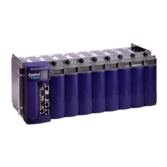
Troubleshooting troubleshooting procedures. 1.2 Physical Description Each ControlWave has a printed circuit board (PCB) backplane mounted in a stainless steel housing, a Power Supply/Sequencer Module (PSSM), a CPU module which may include an optional Secondary Communication Board (SCB) and—depending on the backplane and housing size—up to eight I/O modules. -
Page 9: Housings
One or more I/O modules (see Section 1.6 and Chapter 3) 1.3 Housings ControlWave housings are stainless steel designed for panel-mounting or for some versions, for mounting in a 19-inch equipment rack. They contain the printed circuit board (PCB) backplane into which you connect the PSSM, the CPU module, and any I/O modules. -
Page 10: Controlwave Housing Options
ControlWave Instruction Manual (CI-ControlWave) Figure 1-2. ControlWave Housing Options Introduction Revised Nov-2010... -
Page 11: Cpu Module
CWPAC available on our website http://www.emersonprocess.com/remote. 1.4 CPU Module The CPU (central processing unit) module houses the multi-layer PCB, which contains the ControlWave CPU, I/O monitor/control, memory, and communication functions. It also may include the optional Secondary Communications Board (SCB). The CPU module includes: ... - Page 12 The CPU module contains 64MB of synchronous dynamic random access memory (SDRAM). SDRAM holds the running application (ControlWave project) as well as a copy of system firmware and the current values of any variables not marked RETAIN or stored in the static memory area.
-
Page 13: Power Supply/Sequencer Module (Pssm)
Chapter 2 includes instructions for installing and configuring the PSSM. 1.6 I/O Modules The ControlWave supports analog input, analog output, digital input, digital output, universal digital input, isolated RTD, and isolated low level analog input modules for either local or remote field device wiring termination. -
Page 14: Software Tools
Software Tools The ControlWave programming environment consists of a set of integrated software tools which allow you to create, test, implement, and download complex control strategies for use with the ControlWave. Figure 1-4 graphically presents the programming environment. Introduction Revised Nov-2010... -
Page 15: Controlwave Programming Environment
(document D5084), and the ControlWave Designer Programmer’s Handbook (document D5125). The I/O Configurator, accessible via a menu item in ControlWave Designer, allows you to define process I/O modules in the ControlWave and configure the individual mapping of I/O points for For information on the I/O digital and analog inputs and outputs. - Page 16 Internet Protocol (IP) - You can use an Ethernet port or use a serial port using serial IP using Point-to-Point Protocol (PPP). Other supported protocols include: Modbus, Allen-Bradley DF1, CIP, DNP3, and Hex Repeater. See the ControlWave Designer online help for details and restrictions. 1-10...
-
Page 17: Chapter 2 - Installation
ControlWave Instruction Manual (CI-ControlWave) Chapter 2 – Installation This chapter discusses the physical configuration of the ControlWave, considerations for installation, wiring instructions for the PSSM module, and instructions for setting switches and jumpers on the CPU module. For instructions on I/O installation, see Chapter 3. -
Page 18: Class I, Div 2 Installation Considerations
Make sure that the ControlWave is not exposed to a level of vibration that exceeds that provided in the technical specifications.. Placement of the ControlWave in Class 1, Division 2 (Group A, B, C, and Caution D) hazardous locations requires that you select an appropriate enclosure that meets NEMA Type 3X or 4X specifications. -
Page 19: Unpacking Components
Adding the ControlWave to an OpenBSI network Downloading the application-specific ControlWave project into the ControlWave : Steps 2 through 7 require that you install and use ControlWave Note Designer software on your PC. This manual focuses on hardware installation and preparation. Software installation and configuration is beyond the scope of this manual. -
Page 20: Color Coding Of Slot Connectors
I/O modules go in any other slot (Green tab) 2.2.3 Mounting the Housing You can install a ControlWave equipped with a 4-I/O module housing on a wall or panel. See Figure 2-2 for mounting hole patterns for a 4- I/O unit. - Page 21 ControlWave Instruction Manual (CI-ControlWave) Figure 2-1. 8-I/O Module ControlWave - Mounting Diagram Revised Nov-2010 Installation...
-
Page 22: Grounding The Housing
Once you install the housing, you must run a ground wire between the housing ground lug and a known good earth ground. When you install the various ControlWave modules into the housing and secure them using the captured panel fasteners, this automatically connects them to chassis ground. -
Page 23: Power Supply/Sequencer Module (Pssm)
ControlWave Instruction Manual (CI-ControlWave) : After you install the PSSM in the housing, as an added Note precaution we recommend that you run a #14 AWG wire from the TB2-5 power connection (chassis ground) to the same known good earth ground. - Page 24 ControlWave Instruction Manual (CI-ControlWave) Figure 2-3. Power Supply/Sequencer Module (PSSM) Installation Revised Nov-2010...
-
Page 25: General Information About The Pssm
ControlWave enters a “watchdog” condition in which the CPU cannot control your process. This occurs on power-up before the ControlWave project starts, if the unit is reset, if the ControlWave project “crashes” or if the system loses power. See Section 2.3.5. -
Page 26: General Wiring Guidelines
TB1 and TB2 to the PSSM until after you install, wire, and configure the CPU module. Follow the instructions in Section 2.3.3 General Wiring Guidelines when wiring connections. The ControlWave operates from +22.2 Vdc to +30.0 Vdc (with a Operating nominal +24Vdc input source). Range... - Page 27 6 LLAI Module See table (no surge current) So, for example, if you have a ControlWave with a 16AI module, an 8AO module, and a 32DI module, the maximum current draw is 1A for the CPU plus 2A for the 16AI module plus 1A for the 8AO module and 1A for the 32DI module, for a total of 5A.
-
Page 28: Steady State Current Draw For Bulk Power Supplies
ControlWave Instruction Manual (CI-ControlWave) Table 2-1. Steady State Current Draw for Bulk Power Supplies Component(s) System Current Field Current draw for Notes draw for 24Vdc 24Vdc Power Supply Power Supply CPU (with Ethernet), 290 mA Not applicable PSSM and backplane... - Page 29 ControlWave Instruction Manual (CI-ControlWave) Figure 2-4 shows the typical wiring at the PSSM’s TB1 block. Figure 2-4. PSSM Wire Routing Diagram : As an added precaution, we recommend that you run a #14 Note AWG wire from the TB2-5 power connection (chassis ground) to the same known good earth ground used for the housing.
- Page 30 ControlWave Instruction Manual (CI-ControlWave) Figure 2-5. PSSM TB2 – Typical Wiring Schemes 2-14 Installation Revised Nov-2010...
-
Page 31: Wiring An External Alarm Or Annunciator To The Watchdog Connector And Wiring The Redundancy Control Input (Optional)
Watchdog of the watchdog connector is to trigger an external alarm or annunciator Condition if the ControlWave enters a “watchdog” condition in which the CPU cannot control your process. A watchdog condition occurs when: A watchdog timer expires. This happens if the ControlWave project ... -
Page 32: Watchdog Mosfet Switch Wiring
ControlWave Instruction Manual (CI-ControlWave) You must power the watchdog connector (TB1) from an external power Terminal Block supply. Unplug removable connector TB1 from the PSSM and wire Connector TB1 power to the connector. We recommend you do not plug the connector back into the PSSM until the CPU module is already installed in the housing. -
Page 33: Controlwave To Controlwave Red I/O Redundancy Field Wiring
ControlWave Instruction Manual (CI-ControlWave) Figure 2-7. ControlWave to ControlWave RED I/O Redundancy Field Wiring Revised Nov-2010 Installation 2-17... -
Page 34: Cpu Module
ControlWave Instruction Manual (CI-ControlWave) 2.4 CPU Module The CPU module, which controls the ControlWave and handles memory and communication functions, can only be installed in Slot #2 of the ControlWave backplane. Identify the carton holding the CPU module and remove it from that carton. -
Page 35: Setting Dip Switches On The Cpu Module
ControlWave Instruction Manual (CI-ControlWave) Figure 2-9. ControlWave CPU Module (with SCB) 2.4.1 Setting DIP Switches on the CPU Module Before you install the CPU module, you must determine the settings for its DIP switches. Refer to Figure 2-8 for the location of the DIP switch banks on the CPU board itself. -
Page 36: Soft Switches
OFF (Redundancy Enabled. This ControlWave is one of two in a redundant pair) Unit A / Unit B Specifies whether this ControlWave is the “A” or “B” unit in a redundant pair. Values are: ON (“A” unit in the redundant pair; factory default) OFF (“B”... -
Page 37: Cpu Module Switch Sw3
ControlWave Instruction Manual (CI-ControlWave) Table 2-3. CPU Module Switch SW3 SW3 Setting Function Mode Not currently used. System Enables / disables remote system firmware upgrade via Firmware load System Firmware Downloader: control ON (disables remote system firmware upgrade) OFF (enables remote system firmware upgrade; factory... -
Page 38: Connections To Rs-232 Serial Port(S)
RS-232 port, depending upon the type of SCB. RS-232 COM ports are assigned names based on their location in the RS-232 COM ControlWave. The CPU board has two RS-232 ports (COM1 and Port Names and COM2). See Table 2-5. - Page 39 purchase RJ45 to DB9 Adapter cable(s) using part number 392844- 01-0 to use with the null modem cable. : You can configure the ControlWave as either a master or slave Note node on a BSAP network. Figure 2-10 illustrates the CPU module’s male 9-pin D-type connector.
-
Page 40: Male Db9 9-Pin Connector
ControlWave Instruction Manual (CI-ControlWave) Figure 2-10. Male DB9 9-Pin Connector Table 2-7. COM1 & COM2 RS-232 Port Connector Pin Assignment RS-232 Signal RS-232 Description Data Carrier Detect Input Receive Data Input Transmit Data Output Data Terminal Ready Output Signal/Power Ground... -
Page 41: Full-Duplex And Half-Duplex Cable
Clear to Send Input Data Terminal Ready Output Signal/Power Ground Use the “null modem” cable for full-duplex (PPP protocol) communications when connecting a ControlWave to a PC. (See top part of Figure 2-12.) CW or PC 9-Pin Female 9-Pin Female “D”... -
Page 42: Connecting To A Modem Or Radio
ControlWave Instruction Manual (CI-ControlWave) 3305/3310/3330/3335/CW_10/30/35 9-Pin Male 9-Pin Female “D” Connector “D” Connector 1 = DTR 1 = DCD To P2 Pin-1 6 = CTS Full-duplex 2 = TXD 2 = RXD To P2 Pin-2 7 = DCD To P2 Pin-4... -
Page 43: Connections To Rs-485 Serial Port(S) On Secondary Communication Board (Scb)
: Control DTR using the PORTCONTROL function block and Note the _Pn_AUTO_DTR system variable in your ControlWave project. If you turn DTR off through these mechanisms, the port remains off, even though hardware is fully configured. When port is set for half-duplex operation, CTS must go low after ... - Page 44 Wire the master node to one end of the RS-485 cable run using a 24-gauge paired conductor cable (such as a Belden 9843). : ControlWave only supports half-duplex RS-485 networks. Note Table 2-12. RS-485 Network Connections...
-
Page 45: Connections To Ethernet Port(S) On The Cpu Module
2.4.4 Connections to Ethernet Port(s) on the CPU Module The ControlWave can support from one to three Ethernet ports. These use a 10/100Base-T RJ-45 modular connector that provides a shielded twisted pair interface to an Ethernet hub. Two LEDs per port provide transmit and receive status indications: Table 2-13 shows port assignments for the Ethernet ports. -
Page 46: Bezels
ControlWave Instruction Manual (CI-ControlWave) 10/100Base-T connectors. Figure 2-17. Standard 10/100Base-T Ethernet Cable (CPU Module to Hub) Table 2-14. Ethernet 10/100Base-T CPU Module Pin Assignments Description Transmit Data+ (Output) Transmit Data– (Output) Receive Data+ (Input) Not connected Not connected Receive Data– (Input) -
Page 47: Bezel Assembly
ControlWave Instruction Manual (CI-ControlWave) You should install the bezel whenever the ControlWave is operational. The bezel includes a door you can open to access the PSSM and CPU modules. If necessary, you can remove the bezel for maintenance procedures. To install the bezel, align the snaps on the bezel with the corresponding holders on the chassis. - Page 48 This page is intentionally left blank...
-
Page 49: Chapter 3 - I/O Modules
3.10 Isolated Low Level Analog Input (LLAI) Module ......3-39 Installation Installing any I/O module in the ControlWave involves the same basic steps: Remove the I/O module from the shipping carton. I/O modules include a removable terminal housing assembly. This assembly has a door that swings downward to provide access to the unit’s terminal... -
Page 50: Terminal Housing Assembly Removal
Replace the module’s terminal housing assembly. Figure 3-1. Terminal Housing Assembly Removal Using a PC running the ControlWave Designer and OpenBSI software, configure the ControlWave to accept the new I/O modules and download the revised ControlWave project. Note: This step is beyond the scope of this manual. Refer to the ControlWave Designer Programmer’s Handbook (D5125) -
Page 51: Module Placement
The ControlWave process automation controller supports “hot Caution swapping” of I/O modules, but before any I/O modules can become operational, you must use ControlWave Designer to configure the project to accept the new I/O module, and then compile and download the revised application (project). -
Page 52: Status Leds
ControlWave Instruction Manual (CI-ControlWave) Figure 3-2. ControlWave Chassis Slot Assignments (with/without bezel shown) 3.2 Status LEDs Most of the I/O modules include one or more light emitting diodes (LEDs) to provide diagnostic or status indications. See Chapter 5 for information on the different LEDs. -
Page 53: Local Termination
DIN-rail mounted terminal assembly and then to field devices). ControlWave I/O modules use compression-type terminals that accommodate up to #14 AWG wire. Insert the wire’s bared end (approx. ¼” max) into the clamp beneath the screw and secure the wire. To prevent shorts, ensure that no bare wire is exposed. -
Page 54: Remote Termination
ControlWave Instruction Manual (CI-ControlWave) 3.2.2 Remote Termination For I/O modules that support remote terminations, install cables between the module’s remote headers and the remote DIN-rail mounted terminal block assemblies (see Figure 3-4). Install field wiring between the DIN-rail mounted terminal bock assembly and field devices (see the wiring diagrams associated with each I/O module description). - Page 55 ControlWave Instruction Manual (CI-ControlWave) Figure 3-4. I/O Module (Remote Termination) Wire Routing Revised Nov-2010 I/O Modules...
-
Page 56: Digital Input (Di) Modules
+21Vdc power supply (dry contacts). Note: Early versions of ControlWave DI modules required you to specify either internal or external sourcing for all DIs when you ordered the module; now you can set this yourself using jumpers on a per DI basis. - Page 57 ControlWave Instruction Manual (CI-ControlWave) for use in dry contact applications contain a +21 Vdc isolated power supply powered through an output of the hot swap circuitry which receives power originating on the backplane. Setting Jumpers You must set configuration jumpers for each DI. according to Table 3- 3.
-
Page 58: Di Module - Local Terminal Block Assembly Assignments
ControlWave Instruction Manual (CI-ControlWave) Figure 3-6. DI Module - Local Terminal Block Assembly Assignments Figure 3-7. Internally Sourced DI Module - Wiring Diagram Figure 3-8. Externally Powered DI Module - Wiring Diagram 3-10 I/O Modules Revised Nov-2010... -
Page 59: Remote Din-Rail Mountable
FUSES: F0 to F7: 1/8A, F+: 2A Figure 3-9. Remote DIN-Rail Mountable Terminal Block Assembly Assignments Software Configuration To use data from any ControlWave DI module you must add a CW_DI32 board in ControlWave Designer’s I/O Configurator, and then configure it. See the ControlWave Designer Programmer's Handbook (D5125) for more information. -
Page 60: Remote Din-Rail Mountable Terminal Block Assembly Assignments For Relay Isolated 120Vac Di Operation
ControlWave Instruction Manual (CI-ControlWave) Figure 3-10. Remote DIN-Rail Mountable Terminal Block Assembly Assignments for Relay Isolated 120Vac DI Operation 3-12 I/O Modules Revised Nov-2010... -
Page 61: Digital Output (Do) Modules
ControlWave Instruction Manual (CI-ControlWave) 3.5 Digital Output (DO) Modules DO modules provide 32 or 16 DOs to control signaling functions. DO modules consist of a DO PCB with either a terminal block assembly (for local termination) or a header block assembly (for remote termination). -
Page 62: Local Terminal Block Assembly
ControlWave Instruction Manual (CI-ControlWave) module with failed hardware. For critical processes, the redundant DO with read-back capability is recommended. Use the same DO module type in any redundant pair; do not install a DO with read-back module in the primary controller and a standard DO module as its redundant counterpart in the backup controller, or vice versa. -
Page 63: Assignments For Open Source
ControlWave Instruction Manual (CI-ControlWave) FUSES: F0 to F7: 1A, F+: 2A Figure 3-13. Remote DIN-Rail Mountable Terminal Block Assembly for Open Source Isolated DO Operation Assignments Revised Nov-2010 I/O Modules 3-15... - Page 64 Figure 3-14. Remote DIN-Rail Mountable Terminal Block Assembly Assignments for Relay Isolated 24Vdc DO Operation Software Configuration To use data from any ControlWave DO module you must add a CW_DO32 board in ControlWave Designer’s I/O Configurator, and then configure it. See the ControlWave Designer Programmer's...
- Page 65 DO module and the standby DO module are handled in redundant systems with DO readback. Information on configuring system variables is included in the ControlWave Designer Programmer’s Handbook (D5125). If there is a discrepancy between the value of the online and standby DOs, the system sets a status variable to TRUE.
- Page 66 ControlWave Instruction Manual (CI-ControlWave) failover to the standby. When you set this system variable to FALSE, the system treats a DO readback failure in the associated device as an error; failover is inhibited. When you set this variable to TRUE, the system treats a DO...
-
Page 67: Analog Input (Ai) Modules
Surge suppression and signal conditioning. Cable Shields Connect cable shields associated with AI wiring to the ControlWave housing ground. Multiple shield terminations require that you supply a copper ground bus (up to a #4 AWG wire size) and connect it to the housing’s ground lug. -
Page 68: Internally Sourced 4-20Ma
ControlWave Instruction Manual (CI-ControlWave) Table 3-7 Analog Input Module Configurations Part Number Number of AIs Termination Notes Connector 4-20 mA 396352-01-4 Local 4-20 mA 396352-03-0 Local 4-20 mA 396352-11-1 Remote 4-20 mA 396352-13-8 Remote 396352-14-6 Remote 1-5 Vdc Wiring the Module Figure 3-18 shows terminal assignments for a locally terminated AI module;... -
Page 69: Externally Powered Isolated
Figure 3-17. Externally Powered Isolated 1-5 Volt AI - Wiring Diagram Figure 3-18. Local AI Module Terminal Blocks Assembly Assignments Software Configuration To use data from any ControlWave analog input module you must add a CW_AI16 board in ControlWave Designer’s I/O Configurator, and then configure it. - Page 70 ControlWave Instruction Manual (CI-ControlWave) FUSES: F0, F2, F4, F6: 1/8A for 4-20 mA AI Figure 3-19. Remote DIN-Rail Mountable Terminal Block Assembly Assignments Operation 3-22 I/O Modules Revised Nov-2010...
- Page 71 ControlWave Instruction Manual (CI-ControlWave) FUSES: F0, F2, F4, F6: 1/8A for 1-5V AI Figure 3-20. Remote DIN-Rail Mountable Terminal Block Assembly Assignments Operation Revised Nov-2010 I/O Modules 3-23...
-
Page 72: Analog Output (Ao) Modules
ControlWave Instruction Manual (CI-ControlWave) 3.7 Analog Output (AO) Modules AO modules support eight 4–20 mA analog outputs. AO modules consist of an AO PCB (with a daughter board when configured for read- back) an LED board, a terminal housing assembly, as well as I/O assembly and mounting hardware. - Page 73 ControlWave Instruction Manual (CI-ControlWave) Table 3-9. Analog Output Module Configurations Part Number Number of Termination Notes Connector 4-20mA 396353-01-0 local 4-20mA 396353-11-8 remote 396353-20-7 remote 4-20mA AO Readback on this module Wiring the Module Figure 3-21 shows field wiring assignments for a locally terminated AO module.
- Page 74 ControlWave Instruction Manual (CI-ControlWave) FUSES: F0, F2, F4, F6: 1/8A for AO 4-20mA Figure 3-22. Remote DIN-Rail Mountable Terminal Block Assembly Assignments Operation 3-26 I/O Modules Revised Nov-2010...
- Page 75 ControlWave Instruction Manual (CI-ControlWave) Figure 3-23. 4-20mA Current Loop AO - Wiring Diagrams Software Configuration To use data from any ControlWave analog output module you must add a CW_AO8 board in ControlWave Designer’s I/O Configurator, and then configure it. See the ControlWave Designer Programmer's Handbook (D5125) for more information.
- Page 76 You should configure these variables as alarms so you receive notification of a failure of the backup AO module. See the ControlWave Designer online help for information on alarm configuration. When a read-back failure occurs, the FAIL LED remains RED until the...
-
Page 77: Universal Digital Input (Udi) Modules
ControlWave Instruction Manual (CI-ControlWave) 3.8 Universal Digital Input (UDI) Modules Universal Digital Input (UDI) modules include six inputs which you can individually configure as high speed counters or polled inputs. UDI modules consist of a UDI PCB, either a terminal board assembly... -
Page 78: Jumper Locations
ControlWave Instruction Manual (CI-ControlWave) Table 3-11. UDI Module Configurations Part Number Number of UDIs Termination Connector 396362-02-8 local 396362-12-5 remote Setting Jumpers Each input has a jumper to enable/disable debounce. Enabling debounce activates filters that reduce spurious pulses caused by relay contact bounce. - Page 79 ControlWave Instruction Manual (CI-ControlWave) Table 3-12. Jumper Assignments: UDI Module Jumper Purpose Description Configures UDI1 Pins 1-2 installed = Enable Debounce (Factory default). A change of state on both the SET and RST (reset) field inputs is required to accumulate counts.
-
Page 80: Terminal Block Assembly
ControlWave Instruction Manual (CI-ControlWave) Terminal Block Assembly Assignments FIELD Field CIRCUITRY UDI Operation HSCSET HSCCOM +HSCSET1 +HSCSET2 HSCCOM1 HSCCOM2 +HSCRST1 +HSCRST2 HSCRST +HSCSET3 +HSCSET4 HSCCOM3 HSCCOM4 ‘A’ +HSCRST3 +HSCRST4 +HSCSET5 +HSCSET6 Relay Contact HSCCOM5 HSCCOM6 +HSCRST5 +HSCRST6 FIELD Field CIRCUITRY... -
Page 81: Terminal Block Assembly
ControlWave Instruction Manual (CI-ControlWave) Cable Assembly (One of 2 Cables) End of cable that interfaces with Remote UDI Module’s Header Block Assembly End of cable that interfaces with Remote UDI Module’s DIN-Rail Mountable Terminal Block Assembly From P1 From P2... -
Page 82: Selecting Input Type In
ControlWave Designer’s I/O Configurator, and then configure it. The I/O Configurator is where you specify the usage for each input using the Select Filter list box. Figure 3-29. Selecting Input Type in ControlWave Designer I/O Configurator Choose one of the following: “HSC Channel”... -
Page 83: Isolated Resistance Temperature Device (Rtd) Input Module
ControlWave Instruction Manual (CI-ControlWave) 3.9 Isolated Resistance Temperature Device (RTD) Input Module RTD Input modules provide a total of four inputs. Firmware detects the RTD type (2-, 3- or 4 wire) via the installation of jumper wires on the terminal block for 2-wire and 3-wire RTDs (see Figure 3-30). - Page 84 ControlWave Instruction Manual (CI-ControlWave) Table 3-15. Jumper Assignments: Non-isolated HSC Module Jumper Purpose Description Enables/disables LEDs on Pins 1-2 installed = Enable LEDs (Factory default). module Pins 2-3 installed = Disable LEDs Wiring the Module Figure 3-31 shows field wiring assignments for locally terminated isolated RTD modules.
-
Page 85: Local Isolated Rtd Module
Figure 3-31. Local Isolated RTD Module Terminal Block Assembly Assignments Software Configuration To use data from an Isolated RTD Input module you must add a CWM_RTD8 board in ControlWave Designer’s I/O Configurator, and then configure it. See the ControlWave Designer Programmer's Handbook (D5125) for more information. - Page 86 ControlWave Instruction Manual (CI-ControlWave) Figure 3-32. Remote DIN-Rail Mountable Terminal Block Assembly Assignments for Isolated RTD Module Operation 3-38 I/O Modules Revised Nov-2010...
-
Page 87: Isolated Low Level Analog Input (Llai) Module
ControlWave Instruction Manual (CI-ControlWave) 3.10 Isolated Low Level Analog Input (LLAI) Module Low Level Analog Input (LLAI) modules provide six individually isolated differential inputs for thermocouples or 10mV inputs plus one cold junction compensation (CJC) input for temperature compensation at the terminal block. -
Page 88: Isolated Llai Module
ControlWave Instruction Manual (CI-ControlWave) Wiring the Module Figure 3-34 shows field wiring for locally terminated isolated LLAI modules. Figure 3-35 shows field wiring for remotely terminated isolated LLAI modules. The cold junction compensation (CJC) with a built-in RTD provides thermocouple temperature compensation at the terminal block and is electrically isolated. - Page 89 ControlWave Instruction Manual (CI-ControlWave) Figure 3-34. Local Isolated LLAI Module Terminal Block Assembly Assignments Revised Nov-2010 I/O Modules 3-41...
- Page 90 ControlWave Instruction Manual (CI-ControlWave) Figure 3-35. Remote DIN-Rail Mountable Terminal Block Assembly Assignments for Isolated LLAI Module Operation 3-42 I/O Modules Revised Nov-2010...
-
Page 91: Llai Module
ControlWave Instruction Manual (CI-ControlWave) Ranges & Table 3-19 provides the accuracy, resolution and temperature range for Errors the various thermocouples and 10mV LLAI inputs. Table 3-20 lists the RTD error with the CJC. Table 3-19. LLAI Module Input Accuracy and Resolution... - Page 92 Software Configuration To use data from an Isolated Low Level Analog Input module you must add a CW_TC12 board in ControlWave Designer’s I/O Configurator, and then configure it. See the ControlWave Designer Programmer's Handbook (D5125) for more information. That same manual includes an I/O Mapping section that describes, for advanced users, the I/O map for this module.
-
Page 93: Chapter 4 - Operation
Communicating with the ControlWave ..........4-2 4.3.1 Default Comm Port Settings ..........4-2 4.3.2 Collecting Data from the ControlWave .........4-3 Creating and Downloading an Application (ControlWave Project) ..4-3 Creating and Maintaining Backups ..........4-4 4.5.1 Creating a Zipped Project File (*.ZWT) ........4-5 4.5.2 Saving Flash Configuration Parameters (*.FCP) -
Page 94: Communicating With The Controlwave
4.3 Communicating with the ControlWave You communicate to the ControlWave by connecting a cable between a port on your PC workstation and one of the ControlWave ports. See Section 2.4 for more information on communications. The port at the PC workstation must match the configuration of the ControlWave port. -
Page 95: Collecting Data From The Controlwave
RS-232; 9600 baud, 8 bits, no parity, 1 stop bit, BSAP or ControlWave Designer protocol COM3 RS-485 or RS-232 depending upon factory order; 9600 baud, 8 bits, no parity, 1 stop bit, BSAP or ControlWave Designer protocol COM4 RS-485; 9600 baud, 8 bits, no parity, 1 stop bit, BSAP or... -
Page 96: Creating And Maintaining Backups
Otherwise, when the unit is repaired or replaced, you’d have to create a new ControlWave project from scratch, which might take a lot longer than replacing a few damaged modules. Always maintain a backup copy of your ControlWave project in a safe Caution place. -
Page 97: Creating A Zipped Project File (*.Zwt) For Backup
It may be stored on your PC or removable storage media. It may also be downloaded and archived to ControlWave Flash memory where it may be uploaded at a later time for editing. With your current ControlWave project open in ControlWave Designer, perform the following steps: Click File >... -
Page 98: Saving Flash Configuration Parameters (*.Fcp)
Copy the resulting zwt file to backup media (CD-ROM, thumb drive, etc.) If you ever need to restore the project, just open the zwt file in ControlWave Designer, load libraries as needed, then compile the project and download it into the ControlWave. - Page 99 Depending upon how your system is configured, the Flash Configuration – Loading Options dialog box may open. If it does, choose Load from device and wait for the utility to retrieve all parameters from the ControlWave, then skip to step 4, otherwise, just proceed to step 3. Click and wait for the utility to retrieve all parameters from the ControlWave.
-
Page 100: Backing Up Data
ControlWave Instruction Manual (CI-ControlWave) 4.5.3 Backing up Data You can back up certain types of data and restore it if needed. There are other types of data that you can only collect, but you cannot restore. If you have certain variables that represent tuning parameters... -
Page 101: Chapter 5 - Service And Troubleshooting
OpenBSI System Firmware Downloader and either NetView, LocalView, or TechView for communications. o HyperTerminal (included in Windows® XP) : When you service a ControlWave on site, we recommend that Note you close down (or place under manual control) any associated processes. -
Page 102: Upgrading Firmware
Harmful electrical potentials may still exist at the field wiring terminals Caution even though the ControlWave power source may be turned off or disconnected. Do not attempt to unplug termination connectors or perform any wiring operations until you verify that all associated power supply sources are turned off and/or disconnected. -
Page 103: Hyperterminal Mode Menu
= 1, and Flow control: = None and then click OK. Set CPU switch SW3-3 to ON (Force Recovery Mode). Apply power; to the ControlWave. The resident BIOS initializes and tests the hardware, this process is referred to as POST (Power On Self Test). -
Page 104: Send File Dialog Box
Send to start the flash upgrade (see Figure 5- 4). When you see the HyperTerminal Mode Menu again, it means the download has completed. Exit HyperTerminal and power down the ControlWave. If desired, you can disconnect the null modem cable between the ControlWave and the PC. -
Page 105: Removing Or Replacing Components
5.2 Removing or Replacing Components This section provides information on accessing ControlWave modules for testing, as well as removal/replacement procedures. Field repairs to ControlWave process automation controllers are strictly Caution limited to the replacement of complete modules. All modules (CPU, PSSM, and I/O) are factory sealed to prevent tampering. -
Page 106: Removing/Replacing The Cpu Module
Reconnect the cables and reinsert the key, if necessary. 5.2.3 Removing/Replacing the CPU Module Use this procedure to remove or replace the CPU module. If the ControlWave is running, place any critical control processes under manual control. Shut down the ControlWave by disconnecting the power. -
Page 107: Removing/Replacing An I/O Module (Hot Swapping)
ControlWave Instruction Manual (CI-ControlWave) If the ControlWave is running, place any critical control processes under manual control. Shut down the unit by turning off the power. Unplug the cables and PSSM modular connectors for power (TB2) and watchdog (TB1). Remove the bezel assembly. See Section 5.2.2. -
Page 108: I/O Module To Be Replaced
If the ControlWave is running, place any critical control processes that use this I/O module under manual control. Loosen the capture fasteners at the top and bottom of the module by turning them counter-clockwise. - Page 109 ControlWave Instruction Manual (CI-ControlWave) Figure 5-6. Pulling the I/O Module Out of the Housing If you plan to replace this module with a new module, but want to retain all your existing I/O wiring to the terminal blocks, you need to disconnect the terminal block board from the rest of the module.
- Page 110 ControlWave Instruction Manual (CI-ControlWave) Loosen the fasteners at the top and bottom of the terminal board. Figure 5-7. Loosening the Top Fastener Figure 5-8. Terminal Block Board and Terminal Housing Assembly Separated from the Rest of the Module 5-10 Service & Troubleshooting...
- Page 111 ControlWave Instruction Manual (CI-ControlWave) Again, assuming you want to preserve your existing wiring to the terminal blocks, because you haven’t wired to the terminal blocks on the replacement module, remove the terminal block board and terminal housing assembly from the new replacement module.
-
Page 112: Removing/Replacing The Backup Battery
Note module loses power. The system SRAM has a standby current draw of 50 uA maximum for each part. For a ControlWave containing 2MB of SRAM, a worst-case current draw of 110 uA allows a battery life of approximately 8,636 hours. This means... -
Page 113: Checking Leds
ControlWave Instruction Manual (CI-ControlWave) 5.3.1 Checking LEDs ControlWave modules contain light emitting diodes (LEDs) that provide operational and diagnostic functions. Table 5-1 shows LED assignments on modules. Table 5-1. LED Assignments on Modules Module / LED Name LED Color Function and Location... -
Page 114: Port 80 Display
ControlWave Instruction Manual (CI-ControlWave) Module / LED Name LED Color Function and Location Board CR4 – ENET Port 2 Red/Green ON RED = Data Collision (Left – see Figure 5- 11.) CR4 – ENET Port 2 Red/Green ON GREEN = Receiving data (Left – see Figure 5-11.) -
Page 115: Power Switch
ControlWave Instruction Manual (CI-ControlWave) Module / LED Name LED Color Function and Location Board point) LED OFF= no UDI input activity. See Figure 5- RTD Board Status Red/Green ON RED = Fail state/board not recognized. ON GREEN = Normal state. See Figure 5-17. - Page 116 ControlWave Instruction Manual (CI-ControlWave) Figure 5-11. CPU Module (CPU & SCB boards) Port & LED Designations Figure 5-12. Analog Input (AI) Module LED Designations 5-16 Service & Troubleshooting Revised Nov-2010...
-
Page 117: Analog Output (Ao) Module
ControlWave Instruction Manual (CI-ControlWave) Figure 5-13. Analog Output (AO) Module LED Designations Revised Nov-2010 Service & Troubleshooting 5-17... - Page 118 ControlWave Instruction Manual (CI-ControlWave) Figure 5-14. Digital Input (DI) Module LED Designations Figure 5-15. Digital Output (DO) Module LED Designations 5-18 Service & Troubleshooting Revised Nov-2010...
-
Page 119: For Udi
ControlWave Instruction Manual (CI-ControlWave) UDI Bd. Status LED (Red) = UDI Bd. not recognized or failed. UDI Bd . Status LED (Green) = UDI Bd. recognized and normal. ON UDIXX = Input is present Note: The Status LED will turn ON (Red) whenever power is initially applied to OFF UDIXX = Input is not present. - Page 120 ControlWave Instruction Manual (CI-ControlWave) Figure 5-17. RTD Module LED Designations 5-20 Service & Troubleshooting Revised Nov-2010...
-
Page 121: Checking Wiring/Signals
ControlWave Instruction Manual (CI-ControlWave) Figure 5-18. Low Level Analog Input (LLAI) Module LED Designations 5.3.2 Checking Wiring/Signals Check I/O field wiring at the terminal blocks and at the field device. Inspect the wiring for continuity, shorts, and opens. Check I/O signals at their respective terminal blocks (see Table 5-2). -
Page 122: Port 80 Display Codes
Power-On-Self- Test (POST) When you first power up the ControlWave, or if you reset it using the Codes reset switch, the BIOS runs a power-on-self-test (POST) to test the hardware. Normally, the POST codes pass by too quickly for you to see them, and the system enters normal run time, or if the CPU is set for force recovery mode, you see the code “86.”... - Page 123 ControlWave Instruction Manual (CI-ControlWave) HEX Code Definition any init after vector table init is next. setting monochrome mode. setting color mode. toggle parity before optional video ROM. init before video ROM check. control passed to video ROM. video ROM returned control.
-
Page 124: Status Codes
PCI space. Run Time Once your ControlWave project is normally running, the Port 80 display Status Codes is usually blank to conserve power. Table 5-4 shows status codes you may see during run-time. -
Page 125: Reset Switch
Unit Stopped 5.3.4 Reset Switch The reset switch (SW4) is a momentary button that lets you reset (stop and restart) the ControlWave while you test the unit using WINDIAG diagnostic software. Never use the reset switch during normal operation. Caution 5.4 WINDIAG Diagnostic Utility... - Page 126 Use a null modem cable to connect RS-232 ports between the ControlWave and the PC. Use an RS-485 cable to connect the RS- 485 ports of the ControlWave and the PC. Note: For information on port connections and cabling, please see Chapter 2.
- Page 127 ControlWave Instruction Manual (CI-ControlWave) Figure 5-19. NetView Select Start >OpenBSI Tools >Common Tools > Diagnostics. The Main Diagnostics menu (Figure 5-20) displays. Figure 5-20. WINDIAG Main Diagnostics Menu Select the module to be tested. Enter any prompted parameters (slot #, etc.). WINDIAG performs the diagnostics and displays pass/fail results.
-
Page 128: Available Diagnostics
ControlWave Instruction Manual (CI-ControlWave) After performing all diagnostic testing, exit WINDIAG and then exit the NetView if you don’t have any other ControlWave units to test. When you close NetView, the system asks whether you want to close OpenBSI. Select Yes. - Page 129 ControlWave Instruction Manual (CI-ControlWave) Figure 5-21. RS-232 Loop-back Plugs Port 3 (RS-232) use an 8-pin male RJ-45 loop-back plug (shown in left side of Figure 5-21). Figure 5-22. RS-485 Loop-back Plugs Port 3 (RS-485) use an 8-pin male RJ-45 loop-back plug (shown in left side of Figure 5-22).
-
Page 130: Communications Diagnostic
ControlWave Instruction Manual (CI-ControlWave) functioning), you must reconnect (using a now validated port) and test the remaining untested port. Test Procedure Use this procedure to test the comm ports. Connect an external loop-back plug to the port on the CPU or SCB port you want to test. - Page 131 ControlWave Instruction Manual (CI-ControlWave) Click Return to Menu to display the WINDIAG Main Menu. Ethernet Port The Ethernet option on the WINDIAG Main Menu allows you to Loop-back Test select the Ethernet communication port (1 through 3) to test. This test configures the Ethernet port’s ability to transmit and receive via the twisted pair.
-
Page 132: Core Updump
Click Return to Menu to display the WINDIAG Main Menu. 5.5 Core Updump In some cases—such as when a ControlWave fails for no apparent reason—you can upload a copy of the contents of SRAM and SDRAM to a PC for support personnel and service engineers to evaluate. This upload is called a “core updump.”... - Page 133 Updump). Wait for the error condition (typically FF on the Port 80 display). Connect the ControlWave Comm Port 1 to a PC using a null modem cable. Operate the Run/Remote/Local switch as follows: : You must perform each step in less that one second.
- Page 134 Once the core updump completes, set the failed unit’s CPU switch SW1-1 to ON and SW1-4 to ON, if required, and then power cycle the failed unit to receive the sideload to become a valid standby unit. This applies to the ControlWave REDIO as well. 5-34 Service & Troubleshooting...
-
Page 135: Appendix A - Special Instructions For Class I, Division 2 Hazardous Locations
Controller – Special Instructions for Class I, Division 2 Hazardous Locations The ControlWave Process Automation Controller is listed by Underwriters Laboratories (UL) as nonincendive and is suitable for use in Class I, Division 2, Groups A, B, C and D hazardous locations and non-hazardous locations only. - Page 136 This page is intentionally left blank...
- Page 137 Appendix P – Redundant Power Supply Sequencer Module (RPSSM) The Redundant Power Supply Sequencer Module (RPSSM) provides your ControlWave with dual power supplies for operational redundancy. You can use the RPSSM in place of the standard power supply sequencer module (PSSM) in the following ControlWave models: ...
- Page 138 TB1, TB2, and TB3 to the RPSSM until you have installed, wired, and configured the CPU module. Figure P-1. RPSSM Installed in ControlWave Slot #1 of a ControlWave Redundant Controller Setting Jumpers Depending upon how you are using the RPSSM, you may have to change one or more jumpers from their factor default positions.
- Page 139 Redundant Power Supply Sequencer Module (RPSSM) Jumper Position Description Disables the 12V monitor. When disabled, the RPSSM does not report a failure if voltage falls below 12V. If you need to change the jumper positions, unscrew the protective case from the RPSSM using a Phillips screwdriver (see Figure P-2). Figure P-2.
-
Page 140: Jumper Locations
Use terminal blocks TB1 and TB2 to connect an external bulk power supply to the RPSSM. An external 24V power supply (22.2 to 30V) connected to TB1 provides system power to the ControlWave including the CPU boards and I/O boards (see Figure P-4). - Page 141 TB3-7 = VR - Redundant unit control input (Used with ControlWave RED I/O) When using a pair of ControlWave I/O expansion racks, each with an RPSSM, and a ControlWave Redundant I/O and Communications Switch Unit (the redundant I/O switcher), the choice of which unit is “online”...
- Page 142 RPSSM to TB2-3 on the IORCM, and TB2-4 on the IORCOM must to 24V. Figure P-8 shows the location of the IORCM connectors on the ControlWave I/O Switcher. Figure P-7. – ControlWave to ControlWave REDI/O - Redundancy Field Wiring Installation and Use Revised Nov-2010...
- Page 143 Redundant Power Supply Sequencer Module (RPSSM) Figure P-8. – Location of TB2 on ControlWave I/O Switcher Wiring Digital Inputs to indicate Power Supply Failure Each power supply on the RPSSM drives a solid state relay contact closed during normal operation. In a failure, this contact opens. You can optionally wire the contact to a digital input (either externally or internally sourced) to provide indication of a power supply failure.
- Page 144 Redundant Power Supply Sequencer Module (RPSSM) Should a power supply fail, you must use a replacement supply that has Caution an identical bracket assembly (black anodize or gold irridite). The RPSSM must have one power supply with each type of assembly or it will not function.
- Page 145 Redundant Power Supply Sequencer Module (RPSSM) LED Indicators on the RPSSM Three light emitting diodes (LEDs) are visible through the front cover of the RPSSM (see Figure P-10). Table P-3 describes their functions. Table P-3. LED Descriptions Color LED label (when lit) Meaning PWR GOOD...
-
Page 146: Redundant Power Supply Sequencer
Redundant Power Supply Sequencer Module (RPSSM) Specifications Redundant Power Supply Sequencer Module Input Range: 22.2 to 30V DC (24V input supply, nominal) Shutdown occurs at 22.2 nominal for 24V input supply systems, respectively. Temperature Range: Operating: -40 to 85 o C Storage: -40 to 85 o C 15 to 95% non-condensing Relative Humidity:... - Page 147 ControlWave Instruction Manual (CI-ControlWave) Appendix Z – Sources for Obtaining Material Safety Data Sheets This device includes certain components or materials which may be hazardous if misused. For details on these hazards, please contact the manufacturer for the most recent material safety data sheet.
- Page 148 This page is intentionally left blank...
-
Page 149: Index
......3-13, 3-17 for Ethernet ports ......2-30 Disconnecting SRAM Battery ..5-12 RS-232 ......... 2-23 Downloading RS-485 ......... 2-27 the ControlWave project ....4-3 shields .......... 3-19 Checking LEDs ..........5-13 Environmental specifications..... 2-2 Wiring .......... 5-21 Error codes ........5-22 CJC Error Ethernet ports ........ - Page 150 ControlWave Instruction Manual (CI-ControlWave) 1-1. ControlWave with 8 I/O modules 3-2. ControlWave Chassis Slot ............ 1-2 Assignments....... 3-4 1-2. ControlWave Housing Options 1- 3-3. I/O Module (local termination) wire routing........ 3-5 1-3. I/O Modules......1-8 3-4. I/O Module Remote Termination 1-4.
- Page 151 ControlWave Instruction Manual (CI-ControlWave) 3-20. Remote DIN-rail mountable 5-2. HyperTerminal (Ready to terminal block assembly Download)........5-4 assignments for 1-5V AI..3-23 5-3. Send File dialog box ....5-4 3-21. Local AO module terminal 5-4. HyperTerminal (Download in block assembly assignments ..3-25 progress)........
- Page 152 ControlWave Instruction Manual (CI-ControlWave) LocalView........5-2 System Firmware Downloader ..5-2 Jumpers FLASH memory DI ........... 3-9 amount..........1-6 LLAI ..........3-39 Force recovery mode switch .... 2-21 RPSSM...........P-2 RTD..........3-35 UDI ..........3-30 Grounding ........2-6, 3-6 LEDs Hazardous locations ......A-1 Checking ........
- Page 153 Soft Switches installation........2-7 Lock & unlock ......2-19 Removing........2-7, 5-6 Software Replacing ........5-6 used with the ControlWave.... 1-8 Run/Remote/Local switch....4-1 Specifications TB1 Connectors ......2-16 for temperature, humidty, vibration 2- TB2 Connectors ......2-12 Wiring .......... 2-10 SRAM Battery Power switch........
- Page 154 ControlWave Instruction Manual (CI-ControlWave) 2-9. RS-485 Connectors on SCB . 2-27 3-20. LLAI Module RTD Error with 2-10. RS-485 COM3 Port Connector CJC at 25C ......3-43 Pin Assignment ......2-27 4-1. Default Comm Port Settings (by 2-11. RS-485 COM4 Port Connector PCB)...........
- Page 155 ControlWave Instruction Manual (CI-ControlWave) DO..........3-14 RPSSM...........P-4 for redundancy ......2-15 RTD..........3-36 I/O Modules ........3-5 UDI ..........3-31 LLAI ..........3-40 watchdog circuit....2-15, 2-16 PSSM ........... 2-10 IND-7 Index Revised: Nov-2010...
- Page 156 Col. San Pedro de los Pinos PlantWeb and the PlantWeb logo are marks of Emerson Electric Co. The 01180 Mexico, D.F. Emerson logo is a trademark and service mark of the Emerson Electric Co. Mexico All other trademarks are property of their respective owners.