Table of Contents
Advertisement
Available languages
Available languages
Quick Links
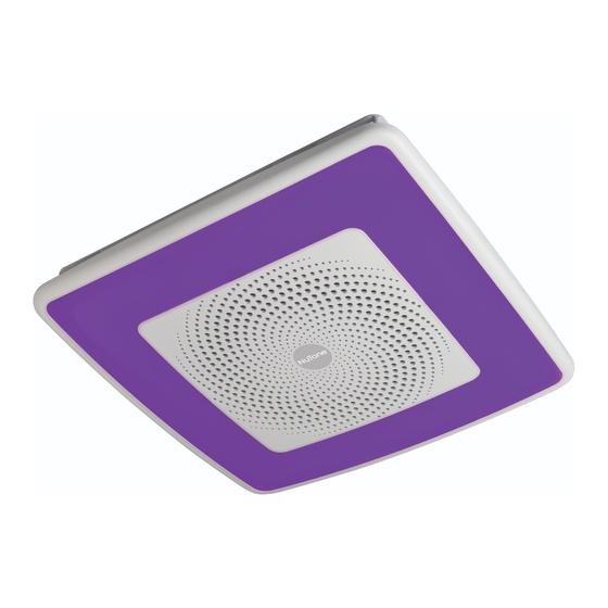
ChromaComfort
Fan/Light/Speaker Installation Instructions
READ AND SAVE THESE INSTRUCTIONS
WARNING
TO REDUCE THE RISK OF FIRE, ELECTRIC SHOCK, OR INJURY TO PERSONS,
OBSERVE THE FOLLOWING:
1. Use this unit only in the manner intended by the manufacturer. If you have questions,
contact the manufacturer at the address or telephone number listed in the warranty.
2. Before servicing or cleaning unit, switch power off at service panel and lock the
service disconnecting means to prevent power from being switched on accidentally.
When the service disconnecting means cannot be locked, securely fasten a
prominent warning device, such as a tag, to the service panel.
3. Installation work and electrical wiring must be done by a qualifi ed person(s) in
accordance with all applicable codes and standards, including fi re-rated construction
codes and standards.
4. Suffi cient air is needed for proper combustion and exhausting of gases through
the fl ue (chimney) of fuel burning equipment to prevent backdrafting. Follow the
heating equipment manufacturer's guideline and safety standards such as those
published by the National Fire Protection Association (NFPA), and the American
Society for Heating, Refrigeration and Air Conditioning Engineers (ASHRAE), and
the local code authorities.
5. When cutting or drilling into wall or ceiling, do not damage electrical wiring and
other hidden utilities.
6. Ducted fans must always be vented to the outdoors.
7. Acceptable for use over a tub or shower when connected to a GFCI (Ground Fault
Circuit Interrupter) - protected branch circuit (ceiling installation only).
8. This unit must be grounded.
CAUTION
1. For general ventilating use only. Do not use to exhaust hazardous or explosive
materials and vapors.
2. This product can be installed in a wall if mounted 8-ft. or more above the fl oor.
3. To avoid motor bearing damage and noisy and/or unbalanced impellers, keep
drywall spray, construction dust, etc. off power unit.
4. Please read specifi cation label on product for further information and requirements.
COOKING AREA
Do not install above or
inside this area.
o
45
NOT FOR USE IN
A COOKING AREA.
IMPORTANT - The ducting from this fan to the outside of the building
has a strong effect on the air fl ow, noise and energy use of the fan. Use the
shortest, straightest duct routing possible for best performance, and avoid
installing the fan with smaller ducts than recommended. Insulation around
the ducts can reduce energy loss and inhibit mold growth. Fans installed
with existing ducts may not achieve their rated airfl ow.
TM
TM
& Sensonic
o
45
Cooking
Equipment
Floor
For Warranty Statement, Service Parts, Technical Support, or to
Register your product, please visit our website or call:
In the United States - broan-nutone.com 800-637-1453 or 888-336-
6151. In Canada - broan-nutone.ca 877-896-1119
CLEANING & MAINTENANCE
For quiet and effi cient operation, long life, and attractive appearance -
lower or remove grille and vacuum interior of unit with the dusting brush
attachment.
The motor is permanently lubricated and never needs oiling. If the motor
bearings are making excessive or unusual noises, replace the blower
assembly (includes motor and impeller).
OPERATION
The ChromaComfort & Sensonic Fan/Light/Speaker must be operated
using only the wall control included. See separate operating instructions.
DO NOT operate the ChromaComfort & Sensonic Fan/Light/Speaker with
any other switches or controls.
The Bluetooth
word mark and logos are registered trademarks owned by Bluetooth
®
and any use of such marks by Broan-NuTone LLC is under license. Other trademark and trade
names are those of their respective owners.
NOTE: This equipment has been tested and found to comply with the limits for a Class B digital
device, pursuant to Part 15 of the FCC Rules. These limits are designed to provide reasonable
protection against harmful interference in a residential installation. This equipment generates,
uses and can radiate radio frequency energy and, if not installed and used in accordance with
the instructions, may cause harmful interference to radio communications. However, there is no
guarantee that interference will not occur in a particular installation. If this equipment does cause
harmful interference to radio or television reception, which can be determined by turning the
equipment off and on, the user is encouraged to try to correct the interference by one or more
of the following measures:
• Reorient or relocate the receiving antenna.
• Increase the separation between the equipment and receiver.
• Connect the equipment into an outlet on a circuit different from that to which the receiver is
connected.
• Consult the dealer or an experienced radio/TV technician for help.
This device complies with Part 15 of the FCC Rules and RSS-210 of Canada. Operation is subject
to the following two conditions:
(1) This device may not cause interference, and (2) this device must accept any interference
received, including interference that may cause undesired operation. FCC IDs: 2ADLL-1103233
& 2ADLL-RGB002 IC : 2143B-1103233 & 2143B-RGB002
This Bluetooth
®
wireless technology enabled luminaire complies with FCC radiation exposure
limits set forth for an uncontrolled environment. End users must follow the specifi c operating
instructions for satisfying exposure compliance. This luminaire must not be co-located or
operate in conjunction with any other antenna or transmitter.
Changes or modifi cations not expressly approved by the party responsible for compliance could
void the user's authority to operate the equipment.
INSULATION
(Place around and
over fan housing.)
FAN
HOUSING
POWER
CABLE *
Seal gaps
around
housing.
4-IN. ROUND
DUCT*
Seal duct joints
with tape.
* Purchase separately.
OPTION - To mount housing anywhere between ceiling framing:
Use optional Hanger Bar Kit (sold separately from local distributors or
website). Follow mounting instructions included with kit.
1
ROOF CAP* (with built-in damper)
OR
WALL CAP*
(with built-in
4-IN. ROUND
damper)
ELBOWS*
®
SIG, Inc.
Keep duct
runs short.
Advertisement
Table of Contents

Related Manuals for NuTone ChromaComfort & Sensonic SPKN110RGBL


Summary of Contents for NuTone ChromaComfort & Sensonic SPKN110RGBL
- Page 1 SIG, Inc. heating equipment manufacturer’s guideline and safety standards such as those and any use of such marks by Broan-NuTone LLC is under license. Other trademark and trade published by the National Fire Protection Association (NFPA), and the American names are those of their respective owners.
-
Page 2: All Installations
ALL INSTALLATIONS Remove all packing material, unplug Remove wiring panel A pair of fl anges and remove blower from fan housing. from fan housing (if may be attached to already installed). housing if desired or required. Snap both fl ange pieces under rolled-over edge of housing (all four sides). -
Page 3: Retrofit Installation
RETROFIT INSTALLATION Remove old 10½-in. Fold mounting ears fan and prepare fl at against housing. ceiling. 9¾-in. JOIST Enlarge ceiling opening (if necessary) to 9¾” (parallel to joist) by 10½” (perpendicular to joist). (Some models have a cut-out template on side of carton.) Existing fan housings are typically attached to the structure: •... - Page 4 Install grille. Connect plug from grille to wire panel. Squeeze grille springs and insert into slots in blower. Push grille up against ceiling. If grille spring becomes dislodged from grille - snap it back into place as shown. Install wall control. 1 11 Note: Location of wall control must be within 20-feet (not obstructed) of grille.
-
Page 5: Nettoyage Et Entretien
ées conformément à la réglementation en vigueur, notamment les normes de la construction ayant trait à la protection contre les incendies. SIG, Inc. et sont utilisés sous licence par Broan-NuTone LLC. Tous les autres noms et marques de commerce appartiennent à leurs propriétaires respectifs. - Page 6 TOUS TYPES DE POSE Retirez tous les matériaux d’emballage, Enlevez le panneau de Il est possible de fi xer débranchez le ventilateur et retirez-le de câblage du boîtier du une paire de brides sur son boîtier. ventilateur (si déjà le boîtier si cela est installé).
-
Page 7: Installation De Rénovation
INSTALLATION DE RÉNOVATION 26,7 cm (10½ po) Enlevez l’ancien Pliez les oreilles de ventilateur et préparez montage à plat contre le plafond. le boîtier. 24,8 cm SOLIVE (9¾ po) Agrandissez l’ouverture (si nécessaire) à 24,8 cm (9¾ po) (parallèle aux solives) par 26,7 cm (10½ po) (perpendiculaire aux solives). - Page 8 Installez la grille. Raccordez les 3 fi ches du boîtier comme indiqué. Pincez les ressorts de la grille et introduisez-les dans les fentes du ventilateur. Poussez la grille contre le plafond. Si le ressort de la grille se déloge de celle-ci, remettez-le en place comme indiqué.