Table of Contents
Advertisement
Available languages
Available languages
Quick Links
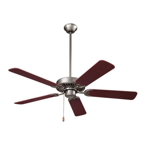
STANDARD SERIES
CEILING FANS
READ AND SAVE THESE INSTRUCTIONS
WARNING
TO REDUCE THE RISK OF FIRE, ELECTRICAL SHOCK, OR INJURY
TO PERSONS, OBSERVE THE FOLLOWING:
1. Use this unit only in the manner intended by the manufacturer. If
you have questions, contact the manufacturer at the address or
telephone number listed in the warranty.
2. Before servicing or cleaning unit, or installing a light kit, switch power
off at service panel and lock service panel to prevent power from
being switched on accidentally. When the service disconnecting
means cannot be locked, securely fasten a prominent warning
device, such as a tag, to the service panel.
3. Installation work and electrical wiring must be done by a qualified
person(s) in accordance with all applicable codes and standards,
including fire-rated construction codes and standards.
4. When cutting or drilling into wall or ceiling, do not damage electrical
wiring and other hidden utilities.
5. This unit must be grounded.
6. Most outlet boxes commonly used for the support of lighting fixtures
are not acceptable for fan support and may need to be replaced,
consult a qualified electrician if in doubt.
Use only UL Listed outlet boxes marked "FOR FAN SUPPORT".
The outlet box and support structure must be securely mounted
and capable of reliably supporting a minimum of 50 pounds. Use
only the two steel screws (and lock washers) provided with the
outlet box for mounting the ceiling fan to the outlet box The outlet
box must not twist or work loose. DO NOT USE PLASTIC OUTLET
BOXES.
7. After marking electrical connections, spliced conductors should
be turned upward and pushed carefully up into outlet box. The
wires should be spread apart with the grounded conductor and the
equipment-grounding conductor on one side of the outlet box.
8. Electrical diagrams are for reference only. Light kits that are not
packed with the fan must be UL Listed and marked suitable for use
with the model fan you are installing. Switches must be UL General
Use Switches. Refer to the instructions packaged with the light kits
and switches for proper assembly.
9. After installation is complete, make sure that all connections are
secure to prevent the fan from falling. Make sure all wire connections
are secure, and that there are no exposed conductor strands.
10. Do not use water or detergents when cleaning the fan or fan blades.
A dry dust cloth or lightly dampened cloth will be suitable for most
cleaning.
MODELS CFS52BS • CFS52PB • CFS52RB • CFS52WH
CAUTION
TO REDUCE THE RISK OF PERSONAL INJURY, OBSERVE THE
FOLLOWING:
1. To avoid motor bearing damage and noisy and/or unbalanced
impellers, keep drywall spray, construction dust, etc. off power unit.
2. The fan must be mounted with at least 7 feet of clearance between
fan blades and floor.
3. Make sure that your installation will not allow the fan to come into
contact with any adjacent obstacles such as doors, hanging lamps,
etc.
4. If you are installing more than one ceiling fan, do not mix the blade
sets.
5. Do not bend the blade brackets.
6. Do not operate reversing switch while fan blades are in motion.
Fan must be turned off and blades stopped before reversing blade
direction.
7. Do not insert objects in between rotating fan blades.
8. Be careful when working around or cleaning the fan.
9. Please read specification label on product for further information
and requirements.
WEIGHT OF FAN
The weight of your fan is 17.8 lbs. The weights of light kits, down rods,
and ceiling adapters are listed in the instructions packed with those
accessories.
INSTALLER:
Leave this manual with the
homeowner.
HOMEOWNER:
Use and care instructions on
pages 7 & 8.
Page 1
Advertisement
Table of Contents

Related Manuals for NuTone STANDARD Series


Summary of Contents for NuTone STANDARD Series
- Page 1 MODELS CFS52BS • CFS52PB • CFS52RB • CFS52WH Page 1 STANDARD SERIES CEILING FANS READ AND SAVE THESE INSTRUCTIONS WARNING CAUTION TO REDUCE THE RISK OF FIRE, ELECTRICAL SHOCK, OR INJURY TO REDUCE THE RISK OF PERSONAL INJURY, OBSERVE THE...
-
Page 2: Tools And Materials Required
MODELS CFS52BS • CFS52PB • CFS52RB • CFS52WH Page 2 CONTENTS Unpack your fan and check the contents. You should have the following items: A - 2-Sided Blade Set (5) B - Hanger Bracket OUTLET BOX C - Canopy D - Downrods (2 - short & long) E - Fan Motor Assembly FIGURE 1 F - Blade Bracket Set (5) -
Page 3: Install The Fan
MODELS CFS52BS • CFS52PB • CFS52RB • CFS52WH Page 3 INSTALL THE FAN UL LISTED ELECTRICAL REMEMBER to turn off the power. Follow the steps below to hang your fan properly. Pass the 120-volt supply wires through the center hole in the ceiling WASHERS CEILING hanger bracket as shown in Fig. -
Page 4: Connect Wiring
MODELS CFS52BS • CFS52PB • CFS52RB • CFS52WH Page 4 CONNECT WIRING 120 VAC LINE IN GREEN Remember to disconnect the power. Follow the steps below to connect GROUND the fan to your household wiring. Use the wire nuts supplied with your fan. -
Page 5: Finish Installation
MODELS CFS52BS • CFS52PB • CFS52RB • CFS52WH Page 5 FINISH INSTALLATION Outlet Box 1. Tuck connections neatly into ceiling outlet box. Ceiling Mounting 2. Slide the canopy up to mounting bracket and place the key hole on Bracket Screw the canopy over the screw on the mounting bracket, turn canopy until it locks in place at the narrow section of the key holes. -
Page 6: Operation
MODELS CFS52BS • CFS52PB • CFS52RB • CFS52WH Page 6 ATTACH FAN BLADES Caution: Remove 5 rubber packing mounts and discard before installation. Your fan is equipped with 2-sided reversible blades. Select the finish and install the blade brackets over the side of the blades that will be visible. Attach the blade to the blade bracket using the screws and fiber SCREWS washers as shown in Figure 12. -
Page 7: Maintenance
MODELS CFS52BS • CFS52PB • CFS52RB • CFS52WH Page 7 MAINTENANCE TROUBLESHOOTING Fan will not start. IMPORTANT: MAKE SURE THE POWER IS OFF AT THE ELECTRICAL PANEL BOX BEFORE YOU ATTEMPT ANY REPAIRS. Check circuit fuses or breakers. REFER TO THE SECTION “CONNECT WIRING”. 2. -
Page 8: Service Parts
MODELS CFS52BS • CFS52PB • CFS52RB • CFS52WH Page 8 SERVICE PARTS PART NO. DESCRIPTION 1 S77000873 BLADE SET (CONTAINS 5) (CFS52WH) S77000874 BLADE SET (CONTAINS 5) (CFS52BS) S77000875 BLADE SET (CONTAINS 5) (CFS52PB) S77000876 BLADE SET (CONTAINS 5) (CFS52RB) 2 S77000856 MOUNTING BRACKET 3 S77000857 CANOPY (CFS52WH) S77000858 CANOPY (CFS52BS) -
Page 9: Warranty
REMEDY: During the applicable limited warranty period, NuTone will, at its option, provide replacement parts for, or repair or replace, without charge, any Fan or part thereof, to the extent NuTone finds it to be covered by and in breach of this limited warranty. - Page 10 MODELOS CFS52BS • CFS52PB • CFS52RB • CFS52WH Página 10 VENTILADORES DE TECHO DE LA SERIE NORMAL LEA Y GUARDE ESTAS INSTRUCCIONES ADVERTENCIA PRECAUCIÓN PARA REDUCIR EL RIESGO DE INCENDIO, DESCARGA PAR A REDUCIR EL RIESGO DE LESIONES, SIGA L AS ELÉCTRICA O LESIONES, SIGA LAS INDICACIONES QUE SE INDICACIONES QUE SE ENUMERAN A CONTINUACIÓN: ENUMERAN A CONTINUACIÓN:...
-
Page 11: Herramientas Y Materiales Requeridos
MODELOS CFS52BS • CFS52PB • CFS52RB • CFS52WH Página 11 CONTENIDO Desempaque su ventilador y verifique que el contenido esté completo. El paquete debe incluir lo siguiente: A - Juego de paletas de CAJA DE DISTRIBUCIÓN doble faz (5) B - Soporte de suspensión C - Carcasa FIGURA 1 D - Barras descendentes... - Page 12 MODELOS CFS52BS • CFS52PB • CFS52RB • CFS52WH Página 12 INSTALACIÓN DEL VENTILADOR CAJA DE CONEXIONES HOMOLOGADA POR UL NOTA: El ventilador de techo incluye dos conjuntos de suspensión; la instalación de techo estándar que utiliza la barra descendente con bola y montaje en encastre y la instalación “cerca del techo”.
- Page 13 MODELOS CFS52BS • CFS52PB • CFS52RB • CFS52WH Página 13 CABLEADO DE CONEXIÓN ENTRADA DE LÍNEA 120 VCA CABLE A Recuerde desconectar la alimentación eléctrica. Siga los pasos que TIERRA VERDE se indican a continuación para conectar el ventilador a la instalación eléctrica de su hogar.
-
Page 14: Terminación De La Instalación
MODELOS CFS52BS • CFS52PB • CFS52RB • CFS52WH Página 14 TERMINACIÓN DE LA INSTALACIÓN CAJA DE Meta las conexiónes en forma ordenada DISTRIBUCIÓN SOPORTE DE adentro de la Toma de corriente. SUSPENSIÓN TORNILLOS Deslice la cubierta hacia arriba hacia el soporte de montaje y coloque el agujero de posición de la cubierta sobre el tornillo del CARCASA... - Page 15 MODELOS CFS52BS • CFS52PB • CFS52RB • CFS52WH Página 15 CONEXIÓN DE LAS PALETAS Precaución: Retire los 5 soportes de goma de empaque y descártelos antes de la instalación. El ventilador incluye paletas de doble faz reversibles. Seleccione el acabado e instale los soportes de las paletas sobre el lado de las paletas que quedará...
-
Page 16: Mantenimiento
MODELOS CFS52BS • CFS52PB • CFS52RB • CFS52WH Página 16 MANTENIMIENTO SOLUCIÓN DE PROBLEMAS I M PORTANTE: ANTES DE I N TENTAR HACER ALGU NA El ventilador no se enciende. REPARACIÓN, ASEGÚRESE DE QUE LA ALIMENTACIÓN Verifique los fusibles o los disyuntores. ELÉCTRICA ESTÉ... -
Page 17: Piezas De Servicio
MODELOS CFS52BS • CFS52PB • CFS52RB • CFS52WH Página 17 PIEZAS DE SERVICIO CLAVE Nº DE PIEZA DESCRIPCIÓN S77000873 JUEGO DE PALETAS (INCLUYE 5) (CFS52WH) S77000874 JUEGO DE PALETAS (INCLUYE 5) (CFS52BS) S77000875 JUEGO DE PALETAS (INCLUYE 5) (CFS52PB) S77000876 JUEGO DE PALETAS (INCLUYE 5) (CFS52RB) S77000856 SOPORTE DE MONTAJE... - Page 18 NuTone le enviará el ventilador reparado o reemplazado o las piezas de repuesto sin cargo. Usted es responsable de todos los costos de retiro, reinstalación y envío, seguro u otros cargos de flete incurridos en el envío del ventilador o la pieza a NuTone.