Table of Contents
Advertisement
Quick Links
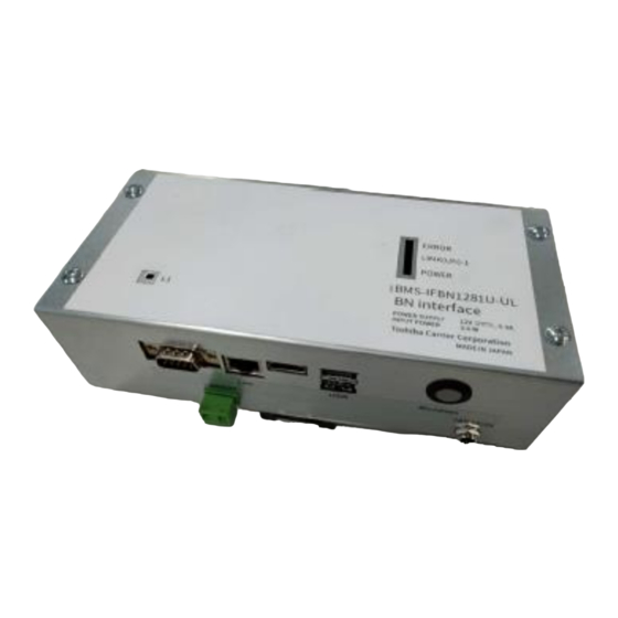
BN interface
Model name:
BMS-IFBN1281U-UL
Multilingual installation manual, license agreement and license information
https://www.toshiba-carrier.co.jp/global/manual/bms-ifbn1281u.htm
[ългарски] Изтегляне на Ръководство за монтаж, Лицензионно споразумение и
Лицензна информация / [Česky] Stažení Montážní příručky, Licenční smlouvy a
Licenčních informací / [Dansk] Download installationsvejledning, licensaftale og
licensinformation / [Deutsch] Installationshandbuch, Lizenzvereinbarung und
Lizenzinformation herunterladen / [Ελληνικά] Λήψη εγγράφων «Εγχειρίδιο
εγκατάστασης», «Άδεια χρήσης» και «Πληροφορίες για την άδεια» / [English]
Installation Manual, License Agreement and License Information Download / [Español]
Descarga del Manual de instalación, del Contrato de licencia y de la Información de
licencia / [Eesti] Paigaldusjuhendi, litsentsi kokkuleppe ja litsentsiteabe allalaadimine /
[Suomi] Asennusohjeiden, lisenssisopimuksen ja lisenssitietojen lataaminen /
[Français] Téléchargement du manuel d'installation, du contrat de licence et des
informations sur la licence / [Hrvatski] Preuzimanje Priručnika za instalaciju, Ugovora o
licenci i Informacija o licenci / [Magyar] Telepítési kézikönyv, Licencszerződés és
Licencinformáció letöltése / [Italiano] Download del Manuale di installazione, del
Contratto di licenza e delle Informazioni sulla licenza / [Latviešu] Uzstādīšanas
rokasgrāmatas, licences līguma un licences informācijas lejupielāde / [Norsk]
Nedlasting av installasjonsveiledning, lisensavtale og lisensinformasjon / [Nederlands]
Installatiehandleiding, Licentieovereenkomst en Licentie-informatie downloaden /
[Polski] Pobieranie Instrukcji instalacyjnej, Umowy licencyjnej i Informacji o licencji /
[Português] Download do Manual de instalação, Contrato de Licença e das
Informações sobre a licença / [Română] Descărcarea Manual de instalare, Contract de
licență și Informații de licență / [Русский] Скачать Руководство по установке,
Лицензионное соглашение и Информацию о лицензии / [Slovensky] Stiahnutie
Montážnej príručky, Licenčnej zmluvy a Informácií o licencii / [Slovenščina] Prenos
navodil za montažo, licenčne pogodbe in licenčnih informacij / [Svenska] Nedladdning
av Installationshandbok, Licensavtal och Licensinformation / [Türkçe] Kurulum
kılavuzu, Lisans Sözleşmesi ve Lisans Bilgileri İndirme / [中文] 安装手册,许可证协议和
许可证信息下载
Installation Manual
Central Control Device
For commercial use
Advertisement
Table of Contents

Related Manuals for Toshiba BMS-IFBN1281U-UL


Summary of Contents for Toshiba BMS-IFBN1281U-UL
- Page 1 Central Control Device For commercial use BN interface Model name: BMS-IFBN1281U-UL Multilingual installation manual, license agreement and license information [ългарски] Изтегляне на Ръководство за монтаж, Лицензионно споразумение и Лицензна информация / [Česky] Stažení Montážní příručky, Licenční smlouvy a Licenčních informací / [Dansk] Download installationsvejledning, licensaftale og licensinformation / [Deutsch] Installationshandbuch, Lizenzvereinbarung und Lizenzinformation herunterladen / [Ελληνικά] Λήψη...
-
Page 2: Table Of Contents
BN interface Installation Manual Contents Precautions for safety ........... . 2 Introduction. -
Page 3: Precautions For Safety
BN interface Installation Manual Precautions for safety The following instructions must be observed. • Carefully read these "Precautions for Safety" before installation, and perform installation work safely. • These precautions contain important information regarding safety. • After installation work, carry out an operation trial to confirm that there are no problems, and explain to the customer how to operate and maintain the system. -
Page 4: Introduction
BN interface Installation Manual Introduction Overview The BN interface refers to equipment used for controlling Building Management Systems (Procured locally) and air conditioners “TU2C-LINK Uh Line (hereinafter, referred to as Uh Line) compatible models” through communications via a network to enable central control. - Page 5 BN interface Installation Manual (Power adapter) 59.05"±0.78" 4.33"±0.01" 1.24" (110.0±0.5) (31.5) (1500.0±20.0) FERRITE AS REQUIRED 1.29"±0.01" 1.18"± 0.19" (33.0±0.5) (30±5) (29.6±0.5) 1.16"±0.01" WIRE NO:1185 0.01" (0.5) GAUGE:16AWG (BLACK) Ø1/2" (Ø12.0) 78.74"±1.96" SPEC LABEL Ø7/32" (2000±50) (Ø5.5) Ø3/32" (Ø2.5) Component Names Unit: inch (mm) Name Function...
-
Page 6: Installation
BN interface Installation Manual Installation REQUIREMENT Do not install the unit in any of the following places. • Humid or wet place • Dusty place • Place exposed to direct sunlight • Place where there is a TV set or radio within 3 ft •... - Page 7 BN interface Installation Manual Installation Space and Maintenance Space A side space for connecting through cable inlets and an upper space for maintenance must be reserved before installation. The other sides can be adjacent to surrounding objects. 3.94" 100 mm 3.94"...
-
Page 8: Power And Signal Line Connections
BN interface Installation Manual Power and signal line connections Cables Use the following cable for signal line connections. (Procured locally) Line Description Type 2-core shielded wires For Uh Line Wire size Refer to "Design of Control Wiring" (P.10 to P.13) Length LAN cable (higher than Category 5, UTP) Type... - Page 9 BN interface Installation Manual Example of System Wiring Connections BN interface Power adapter Power Supply Building Management System Uh Line main bus Outdoor unit Outdoor unit Indoor unit Remote Remote Indoor unit controller controller...
- Page 10 BN interface Installation Manual Termination resistance setting • TU2C-LINK / TCC-LINK termination resistance setting ....<For TCC-LINK> Leave just 1 line of the termination resistance in the interface board of the outdoor unit (centre unit) ON, and turn all the others OFF. (Refer to the wiring diagram attached to the outdoor unit for the position of SW.) <For TU2C-LINK>...
- Page 11 BN interface Installation Manual Design of Control Wiring Communication method and model name The TU2C-LINK model (U series) can be used together with previous models (other than U series). For details of the model and communication method, see the following table. Communication method TU2C-LINK (U series) TCC-LINK (other than U series)
- Page 12 BN interface Installation Manual When the connected outdoor unit is Super Multi u series (U series) Follow the wiring specifications in the table below even when there is a mix of U series and non-U series in the connected indoor units or remote controllers.
- Page 13 BN interface Installation Manual When the connected outdoor units are other than Super Multi u series (U series) Wiring specifications Communication line Item Control wiring between indoor and outdoor units and central control wiring AWG16: Up to 3281 ft (1000 m) Wire diameter AWG14: Up to 6560 ft (2000 m) Wire type...
- Page 14 BN interface Installation Manual When connecting to a previous model light commercial, air to air heat exchanger, air to water heat pump, or general purpose equipment control interface Follow the wiring specifications in the table below even when there is a mix of U series and non-U series in the connected indoor units or remote controllers.
-
Page 15: Settings
BN interface Installation Manual Settings 3-1. Switch setting SW100 Uh Line termination resistance setting switch bit1:use, bit2:not use Refer to "Termination resistance setting" (P.9) Shutdown button Shutdown function / air conditioner search mode function button Use this button to stop BACnet process and network process of the BN interface or to start up in the air conditioner search mode. -
Page 16: Led
BN interface Installation Manual 3-2. LED LED color POWER Power indicator RS485 Green Not use LINK1(Uh) Orange Uh Line communication status indicator LINK2(Uh) Orange Not use ERROR Uh Line communication error indicator Green BACnet communication status indicator, setting error indicator Factory default settings Item Factory default setting... -
Page 17: Test Run
BN interface Installation Manual Test run To perform test run of the BN interface, BACnet communication settings and the equipment data of the connected indoor units are required. Items to be set during trial run Equipment Item Setting method Use the DIP switch on the outdoor Outdoor unit Uh Line address Line address... -
Page 18: Setting Up Equipment Data In The Indoor Unit
BN interface Installation Manual 5-2. Setting up equipment data in the indoor unit Obtain the equipment data of the indoor unit that is controlled by the BN interface from the indoor unit via the Uh Line communication cable. Preparing to set up equipment data in the indoor unit •... -
Page 19: Cause Of Problem Occurring During Setup
BN interface Installation Manual 5-3. Cause of problem occurring during setup Cause of problem Cause Action The indoor and outdoor units have not been Make sure that indoor and outdoor units are turned on. turned on. The indoor and outdoor units are being Make sure that indoor and outdoor units are initialized and it is not possible to turned on. - Page 20 DEC3029101...