Table of Contents
Advertisement
Quick Links
Central Remote Controller
TU2C-LINK / TCC-LINK compatible
Model name
TCB-SC640U-UL
Multilingual installation manuals and owner's manual
https://www.toshiba-carrier.co.jp/global/manual/tcb-sc640u.htm
[English] Installation manual and Owner's manual Download / [Español] Descarga del
Manual de instalación y del Manual del propietario / [Français] Téléchargement du
manuel d'installation et du manuel du propriétaire
Installation Manual
Central Control Device
For commercial use
Advertisement
Table of Contents

Related Manuals for Toshiba TCB-SC640U


Summary of Contents for Toshiba TCB-SC640U
- Page 1 For commercial use Central Remote Controller TU2C-LINK / TCC-LINK compatible Model name TCB-SC640U-UL Multilingual installation manuals and owner’s manual [English] Installation manual and Owner’s manual Download / [Español] Descarga del Manual de instalación y del Manual del propietario / [Français] Téléchargement du manuel d'installation et du manuel du propriétaire...
-
Page 2: Table Of Contents
Central Remote Controller Installation Manual Contents 1 Safety Precautions ........... . 3 2 Specifications . -
Page 3: Safety Precautions
Central Remote Controller Installation Manual Safety Precautions • Read these "Safety Precautions" carefully before installation. • The precautions described below include important items regarding safety. Observe them without fail. Understand the following details (indications and symbols) before reading the body text, and follow the instructions. •... -
Page 4: Specifications
Central Remote Controller Installation Manual Specifications Product name Central Remote Controller Model Name TCB-SC640U-UL Power supply 120 V AC 60 Hz Consumed current 0.1 A Number of connected units Up to 64 units External contact inputs External contact outputs Operating temperature/humidity range 32°F to 104°F (0°C to 40°C), 10% to 90% RH (no condensation) - Page 5 Central Remote Controller Installation Manual ■ Component Names Terminal block for external contact input Terminal block for external contact output Uh / U3U4 terminal block Name Functions Terminal block for external contact output Connect the external contact output Terminal block for external contact input Connect the external contact input Uh / U3U4 terminal block Connect the central control wiring...
-
Page 6: Installation
Central Remote Controller Installation Manual Installation 3-1. Power, Signal, and Ground Connections Connect the power, signal and ground to the specified terminal blocks. REQUIREMENT Attach round crimp terminals to all TU2C-LINK / TCC-LINK wiring and tighten the screws securely. After tightening, check that the wiring cannot come out. Connect the power supply wire and the ground wire (1) Remove 3 cover fixing screws pointed to by arrows and open the cover (2) Insert cross notches in the rubber bushing in order to pass the power supply cable... - Page 7 Central Remote Controller Installation Manual ■ About Stripping Length (Unit: inch (mm)) Power supply wire stripping length Central control wiring stripping Digital I/O cable stripping length length Shielded wire 1.18” (30) 0.78 ”(20) 0.39” (10) 0.59” (15) 2.75” (70) Cut the shield and perform insulation processing.
- Page 8 Central Remote Controller Installation Manual ■ Design of Control Wiring Communication method and model name The TU2C-LINK model (U series) can be used together with previous models (other than U series). For details of the model and communication method, see the following table. Communication method TU2C-LINK (U series) TCC-LINK (other than U series)
- Page 9 Central Remote Controller Installation Manual When the connected outdoor unit is Super Multi u series (U series) Follow the wiring specifications in the table below even when there is a mix of U series and non-U series in the connected indoor units or remote controllers.
- Page 10 Central Remote Controller Installation Manual When the connected outdoor units are other than Super Multi u series (U series) Wiring specifications Communication line Item Control wiring between indoor and outdoor units and central control wiring AWG16: Up to 3281 ft (1000 m) Wire diameter AWG14: Up to 6560 ft (2000 m) Wire type...
- Page 11 Central Remote Controller Installation Manual When connecting to a previous model light commercial, or general purpose equipment control interface Follow the wiring specifications in the table below even when there is a mix of U series and non-U series in the connected indoor units or remote controllers.
- Page 12 Central Remote Controller Installation Manual ■ Connection to External Equipment Connect to external equipment (digital I/O signal wire) Output — common Input common State output Run output Input 3 Alarm output Control input Input 2 Input 1 *Functions can be assigned to inputs 1 to 3 using "Changing the External Input Function (External Input Settings) (P.27)". This unit side Equipment side Name...
- Page 13 Central Remote Controller Installation Manual When using a relay for the circuit on the equipment side of the state output IMPORTANT Be sure to connect freewheeling diodes to both ends of the relay coil. (A relay with a built-in diode is recommended.) (Locally procured) External power supply...
-
Page 14: How To Install
Central Remote Controller Installation Manual 3-2. How to Install CAUTION • Do not wire communication lines (control wiring between indoor and outdoor units, central control wiring) or input/output wiring next to power supply wiring, etc., or house them in the same metal pipe. Doing so may result in failure. •... -
Page 15: Central Remote Controller Test Run
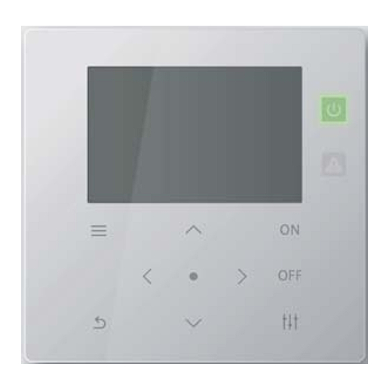
Central Remote Controller Installation Manual Central Remote Controller Test Run • Set according to the following procedure before use. This allows the unit to monitor and operate the air conditioners. Example of All screen Run lamp Check lamp ON button (Menu) button OFF button (Confirm) button... - Page 16 Central Remote Controller Installation Manual Register the indoor units to the unit Example of Obtain Address screen Press the [ ] and [ ] buttons simultaneously for 4 seconds or more on the Line address Indoor address All screen to move to "How to Display the "Servicing Menu" Screen (P.17-2)". Central control Perform "Obtain Address (If you will not change the Central control address address...
-
Page 17: Servicing Menu" Settings
Central Remote Controller Installation Manual "Servicing Menu" Settings ■ How to Display the "Servicing Menu" Screen "All" screen (Menu) button (Control) button Display the "All" screen Press [ ] (Menu) and [ ] (Control) together for more than 4 seconds The "Servicing Menu"... -
Page 18: Register/Check Indoor Unit (Address Settings)
Central Remote Controller Installation Manual Register/Check Indoor Unit (Address Settings) Select "Address Settings" on the "Servicing Menu" screen and press [ ] (Confirm) The "Address Settings" screen appears. Press [˄] and [˅] to select the item, then press [ ] (Confirm) The screen of the selected item appears. - Page 19 Central Remote Controller Installation Manual To change the Central control address Select "Obtain Address" on the "Address Settings" screen and press [ ] (Confirm) The "Obtain Address" confirmation screen appears. Press [˄] and [˅] to select "Yes", then press [ ] (Confirm) "Obtaining address...
- Page 20 Central Remote Controller Installation Manual Address Display The indoor units registered in the unit are displayed. Select "Address Display" on the "Address Settings" screen and press [ ] (Confirm) The "Address Display" confirmation screen appears. Press [˄] and [˅] to select "Yes", then press [ ] (Confirm) The "Address Display"...
-
Page 21: Change The Zone To Which The Indoor Unit Belongs (Zone Settings)
Central Remote Controller Installation Manual Change the Zone to which the Indoor Unit Belongs (Zone Settings) On the "Servicing Menu" screen, select "Zone Settings" and press [ ] (Confirm) The "Zone Settings" screen appears. • The indoor unit list display can be selected from the Central control address order or the Central control address order. -
Page 22: To Change The Group Zone Of Multiple Indoor Units
Central Remote Controller Installation Manual To Change the Group Zone of Multiple Indoor Units When "Central control Address" is selected Perform steps 1 to 2 in "Change the Zone to which the Indoor Unit Belongs" (P.21). The "Address List" screen is displayed. •... -
Page 23: Set The Indoor Unit As Being Out Of The Scope Of Management
Central Remote Controller Installation Manual Set the indoor unit as being out of the scope of management. On the "Zone List" screen, select "Del" then press [ ] (Confirm) The display returns to the "Address List" screen. • The zone number is deleted and will not be included in the number of units on the All screen. -
Page 24: Changing The Display Method (Display Settings)
Central Remote Controller Installation Manual Changing the Display Method (Display settings) On the "Servicing Menu" screen, select "Display settings" then press [ ] (Confirm) The "Display settings" screen appears. Select an item with [˄] and [˅] then press [ ] (Confirm) The screen for the selected item appears. - Page 25 Central Remote Controller Installation Manual Unit Order Settings Set the display order of indoor units on the "Unit" screen. On the "Display settings" screen, select "Unit Order Settings" then press [ ] (Confirm) The "Unit Order Settings" screen appears. Press [˄] and [˅] to select the display order, then press [ ] (Confirm) The display order changes to the selected display order.
-
Page 26: Delete The History And Set The Notice Code (Check/Notice Settings)
Central Remote Controller Installation Manual Delete the History and Set the Notice Code (Check/Notice Settings) On the "Servicing Menu" screen, select "Check/ Notice Settings" then press [ ] (Confirm) The "Check/Notice Settings" screen appears. Press [˄] and [˅] to select the item, then press [ ] (Confirm) The screen for the selected item appears. -
Page 27: Changing The External Input Function (External Input Settings)
Central Remote Controller Installation Manual Changing the External Input Function (External Input Settings) On the "Servicing Menu" screen, select "External Input Settings" then press [ ] (Confirm) The "External Input Settings" screen appears. Press [˄] and [˅] to select the input terminal to set then press [ ] (Confirm) The "Select function"... - Page 28 Central Remote Controller Installation Manual External input function table Icon Setting Items Description Settings Void No function When ON, the air conditioners in the specified Contact A (ON at signal input, OFF at release) zones are stopped. Contact B (OFF at signal input, ON at release) When ON, the air conditioners in the specified Contact A (ON at signal input, OFF at release) zones are operated.
-
Page 29: Switch Operation Mode (Crc Mode Change Conf.)
Central Remote Controller Installation Manual Switch Operation Mode (CRC Mode Change Conf.) On the "Servicing Menu" screen, select "CRC Mode Change Conf." then press [ ] (Confirm) The "CRC Mode Change Conf." screen appears. Press [˄] [˅] to select the mode, then press [ ] (Confirm) Press [ ] (Return) to return to the "Servicing Menu"... -
Page 30: Change Communication Configuration (Communication Conf.)
Central Remote Controller Installation Manual Change Communication Configuration (Communication Conf.) On the "Servicing Menu" screen, select "Communication Conf." then press [ ] (Confirm) The "Communication Conf." screen appears. (1) Indoor unit address acquisition method setting (2) Central controller ID setting Press [˄] and [˅] to select the SW number, then press [<] and [>] to move the cursor to the switch you want to change... - Page 31 Central Remote Controller Installation Manual (1) Indoor unit address acquisition method setting 0: Line address mode 1: Central control address mode (2) Central controller ID setting Central controller ID 1234 5 When using in combination Central controller ID 1 1000 0 •...
-
Page 32: Check The Connection Status Of The Indoor Units
Central Remote Controller Installation Manual Check the Connection Status of the Indoor Units (Communication Check) On the "Servicing Menu" screen, select "Communication Check" then press [ ] (Confirm) The "Communication Check" screen appears. Press [˄] and [˅] to select the item, then press [ ] (Confirm) The screen for the selected item appears. -
Page 33: Register Contact Information When An Error Occurs (Register Contact Info)
Central Remote Controller Installation Manual Register Contact Information when an Error Occurs (Register Contact Info) Contact TEL No. On the "Servicing Menu" screen, select "Register Contact Info" then press [ ] (Confirm) The "Register Contact Info" screen appears. Select "Contact TEL No." with [˄] and [˅] then press [ ] (Confirm) The "Contact TEL No."... - Page 34 DEB5229151...