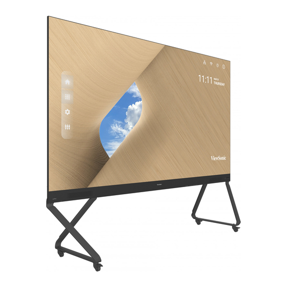
Summary of Contents for ViewSonic LDP163-181
- Page 1 LDP163-181 All-in-One Direct View LED Display Quick Start Guide 快速安装说明 快速入門指南 Guide de démarrage rapide Schnellstartanleitung Guía rápida de inicio Hızlı Başlangıç Kılavuzu Aan de slag краткое руководство по началу работы...
-
Page 3: Package Contents
Sections total and one (1) Right. System Control Box 2 sides (Left and Right sides) LDP163-181 All-in-One Direct View LED Display Quick Start Guide 快速安装说明 快速入門指南 Guide de démarrage rapide Schnellstartanleitung Guía rápida de inicio Hızlı Başlangıç Kılavuzu Aan de slag Quick Start краткое... - Page 4 Item Quantity Note System Control Box Covers (Left, Middle, and Right sides) Wall Mounting Brackets Vacuum Suction Tool Anti-Static 2 pairs Gloves USB-A to USB-B Cable (5m) IR Extender Cable (3m) Replacement LED beads specific to module batch 1 bag number.
-
Page 5: Product Overview
Product Overview Front Panel USB C USB A HDMI AUDIO AUDIO S/PDIF HDMI 1 HDMI 2 HDMI 3 HDMI 4 HDMI 5 POWER IR IN 5V/1.5A 5V/1.5A (2.0) (2.0) (1.4) (1.4) (2.1) RS232 Speaker Speaker Power Switch I/O & Control Panel Rear Panel... -
Page 6: Before Installing
Introduction Before Installing Maintain an adequate air gap between the back of the display and any wall for proper ventilation. Ensure there is no direct airflow from air conditioning or heating vents blowing on the display. Avoid installing the display in places with high humidity. Due to high power usage, always use power cords specifically designed for this product. - Page 7 5. Install the Lower Wall Mount Brackets in the same manner as the Upper Wall Mount Brackets. The distance between the Upper and Lower Wall Mount Brackets is 66 ²⁷/₆₄" (1687.25 mm). 2 ¹/₄ in 4 ¹/₆₄ in ⁶³/₆₄ in NOTE: ...
-
Page 8: Installing The Cabinets
Installing the Cabinets 1. Ensure the Mounting Brackets on the rear of the six (6) Cabinets are positioned at the top and bottom mounting positions as shown below: 2. Carefully lift each Cabinet up onto the Upper Wall Mount Brackets, starting from the left. - Page 9 4. Push each Locking Bolt and lock each Hook with the hex tool to securely connect each cabinet together. It may be necessary to align the hole with an Allen wrench in order to engage the Locking Bolt. Push the Locking Bolt. Lock each Hook with the hex tool.
- Page 10 5. Place the remaining Cabinets up onto the Upper Wall Mount Brackets. Install from left to right, ensuring the Mounting Brackets sit securely on the Wall Mount Brackets. 6. Repeat Step 4, securing the cabinets together with each Locking Bolt and Hook. Push the Locking Bolt.
- Page 11 Connecting the System Control Box 1. Carefully unfold the System Control Box panel. Ensure the main system control board is on the right. NOTE: Use caution as the System Control Box panel is separated into two pieces with wires attached. 2.
- Page 12 3. You can also reroute the power cable for cable management. Loosen the two (2) PWM 4x6mm screws, pull the power cable out, thread the power cable through the hole and then fasten the screws tightly. Hole for cable management Two (2) PWM 4x6mm Screws Professional installation only.
- Page 13 4. Further secure the System Control Box to the Cabinets with the 20 provided M6x10mm screws. 5. Connect the Network and Power cables of the Cabinets to the System Control Box. NOTE: There are six (6) Network and six (6) Power cables to connect. Network 1 Network 2 Network 3...
- Page 14 Installing the LED Modules Install each LED Module onto the Cabinets, being sure to match the corresponding numbers on the Module to the Cabinet. Please wear Anti-Static Gloves before handling the LED modules. Ensure each Module is flush and that there is little to no gap between each. It may be necessary to gently tap the module to make it flush.
- Page 15 Installing System Control Box Covers There are three (3) System Control Box Covers: Left, Middle, and Right. USB C USB A HDMI AUDIO AUDIO S/PDIF HDMI 1 HDMI 2 HDMI 3 HDMI 4 HDMI 5 POWER IR IN 5V/1.5A 5V/1.5A (2.0) (2.0) (1.4)
- Page 16 NOTE: We also offer a variety of installation options for different scenarios: Floor Stand, Portrait Mode, Detachable Control Box, Dual-Screen Splicing (32:9). Please refer to the User Guide for more details. LDP163-181_QSG_1a_ENG_20221129 Copyright © 2022 ViewSonic Corporation. All rights reserved.


