
Related Manuals for Worcester Highflow 400 Electronic Series


Summary of Contents for Worcester Highflow 400 Electronic Series
-
Page 1: User Instructions
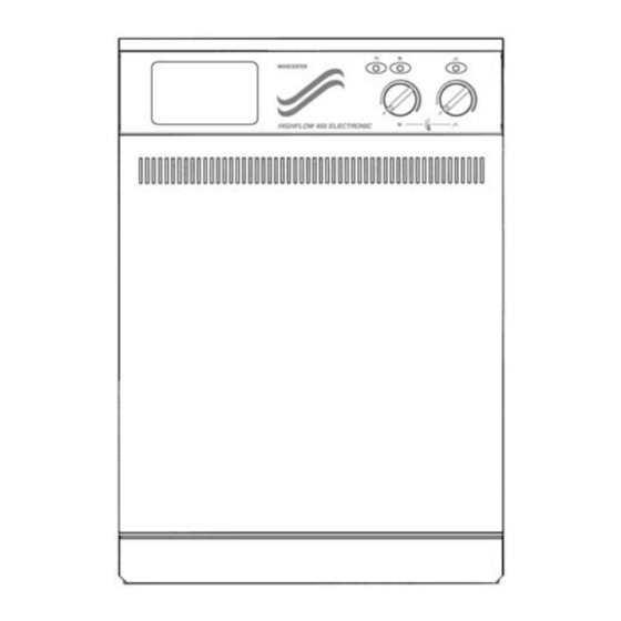
HIGHFLOW 400 ELECTRONIC SERIES G.C. NUMBERS APPLIANCE NATURAL GAS L.P.G. Fanned Flue (RSF) 47 311 61 47 311 64 Balanced Flue (BF) 47 311 62 Open Flue (OF) 47 311 63 USER INSTRUCTIONS & CUSTOMER CARE GUIDE... -
Page 2: Excellence Comes As Standard
Worcester Care Call - a complete maintenance scheme to keep your boiler operating at peak condition and efficiency. No wonder that more and more people are agreeing that when it is gas, it has to be Worcester Highflow 400 Electronic Series. years. -
Page 3: General Information
GENERAL DESCRIPTION (See Fig.1.) The HIGHFLOW 400 ELECTRONIC MODELS are combined domestic hot water and central heating appliances. They consist of a gas fired boiler having a varying output of between 8.8/11 kW and 24... - Page 4 Fig. 1. System Diagram of Highflow 400 Electronic Series. Flow tur- bine From radiators radiators Heat exchanger Circulating pump Water diverter valve Heatbank Primary Water circulation Hot Water and Central Heating Mode: The appliance will supply heat to the central heating system as required.
-
Page 5: General Notes
GENERAL NOTES CENTRAL HEATING SYSTEM During the first few hours of operation of the central heating system, check that all radiators are being heated at an even rate. Should the upper area of a radiator be at a lower temperature than the base of the radiator, it should be vented by releasing air through the venting screw at the top of each radiator. -
Page 6: Room Thermostat
ROOM THERMOSTAT A room thermostat may be fitted for control of the central heat- ing temperature. The method of setting a room thermostat varies with the type and manufacture. Refer to the instructions supplied with the room thermostat. THERMOSTATIC RADIATOR VALVES If thermostatic radiator valves are to be fitted to the system then they must conform to the requirements of BS2767:1972. -
Page 7: Circulating Pump
NOTE: Do not place anything on top of the appliance. If the appliance is fitted in a compartment do not use the compartment for storage purposes unless it conforms to the requirements of BS 6798:1987: Section 6. In particular, the flue pipe should not pass through an airing cupboard space unless protected by a guard (such as wire mesh) concentrically spaced 25mm, as described in BS 6798:1987. -
Page 8: Operation Of Controls
OPERATION OF CON- TROLS The appliance is fitted with a blanking panel or an electronic programmer on the facia panel for the control of domestic hot water and central heating. OPERATING MODES HOT WATER ONLY. The appliance will operate at any time there is a demand for hot water. - Page 9 Fig. 2. Facia panel. CH ON Light Power Light HW ON Light Optional Facia Mounted Programmer Maximum setting Minimum setting Heating Temperature Control Hot Water Temperature Control...
-
Page 10: To Light And Stop The Appliance
Fig. 3. Appliance with cabinet front cover removed Circulating pump Water diverter valve Gas serv- ice cock D Heatbank TO LIGHT AND STOP THE APPLIANCE TO LIGHT THE APPLIANCE See Figs 2 and 3. Set the temperature controls A,B (or programmer C if fitted) to OFF. - Page 11 OVERHEAT THERMOSTATS Overheat thermostats are fitted to the appliance which interrupt the electricity supply to the gas control through the control circuits in the event of overheating. If the appliance fails to light, check that an overheat thermostat has not operated by observing the status of the indicator lights on the facia.
-
Page 12: Appliance Fails To Operate
APPLIANCE FAILS TO OPERATE More than 30% of all calls made to Worcester Heat Systems to report appliance faults or breakdowns prove to be false alarms, as there is often a simple explanation for the apparent malfunction. So, to help you save time and money – not to mention frustration and inconvenience –... -
Page 13: Maintaining Your Appliance
MAINTAINING YOUR APPLIANCE Your new Worcester Highflow 400 Electronic gas-fired appli- ance represents a long-term investment in a reliable, high quali- ty product. In order to realise its maximum working life, and to ensure it continues to operate at peak efficiency and performance, it is... -
Page 14: Service Centres
CONTACT NUMBERS: UK Call Centre UK Call Centre Scotland only OPERATING HOURS: Mon - Fri Please contact our UK Call Centre number where our friendly operators will book your call with one of our team of nationwide engineers. Sunday and Bank Holiday cover is not available Do not touch or adjust any sealed component SERVICE CENTRES Tel. - Page 15 YOUR WORCESTER HIGHFLOW 400 ELECTRONIC SERIES GUARANTEE This appliance is guaranteed against faulty materials or workmanship for a period of twelve calendar months from the date of installation subject to the following conditions and exceptions. 1. That during the currency of this...
-
Page 16: Guarantee Registration
Registration Card within 14 days of purchase. The card will register you as the owner of your new Worcester Highflow 400 Electronic appliance and, while this will not affect your statutory rights in any way, it will assist us to maintain an effective and efficient customer service by estab- lishing a reference and permanent record for your boiler.