
Related Manuals for UNI-T UTG2122B


Summary of Contents for UNI-T UTG2122B
- Page 1 User Manual UTG2000B Series Function/Arbitrary Waveform Generator 2011.09. UNI-T Technologies, Inc.
- Page 3 Preface Dear Users: Hello! Thank you for choosing this brand new Uni-Trend device. In order to use this instrument safely and correctly, please read this manual thoroughly, especially the Safety Notes part. After reading this manual, it is recommended to keep the manual at an easily accessible place, preferably close to the device, for future reference.
-
Page 4: Copyright Information
Any maintenance on altered or integrated products (if such alteration or integration leads to an increase in time or difficulty of product maintenance). This warranty written by UNI-T for this product, and it is used to substitute any other expressed or UTG2000B Series... -
Page 5: Preface
Regardless of whether UNI-T and its distributors are informed that any indirect, special, incidental, or consequential damage may occur, the UNI-T and its distributors shall not be responsible for any of the damages. UTG2000B Series... -
Page 6: Introduction
Introduction This device is economical, high-performance, multi-functional single channel waveform generators. It uses direct digital synthesis (DDS) technology to produce accurate and stable waveforms. It can generate accurate, stable, pure and low distortion output signals; also can provide high-frequency vertical edge square waves. UTG2000B’s convenient interface, superior technical indexes and user-friendly graphical display style can help users to complete tasks quickly and improve work efficiency. -
Page 7: Table Of Contents
Table of Contents Preface..............................3 Copyright Information .......................... 2 Introduction ............................4 Table of Contents ..........................5 Chapter 1 Safety Information ....................... 7 1.1 Safety Terms and Symbols ...................... 7 1.2 General Safety Overview ......................7 Chapter 2 Quick Start ........................... 9 2.1 General Inspection ......................... - Page 8 3.1.8 Quadrature Phase Shift Keying(QPSK) ............... 67 3.1.9 Oscillation Keying(OSK) ....................68 3.1.10 Sum Modulation(SUM) .................... 72 3.1.11 Double side band amplitude Modulation (DSBAM) ..........77 3.1.12 Quadrature Amplitude Modulation(QAM) .............. 81 3.1.13 Pulse Width Modulation (PWM) ................85 3.2 Output Frequency Sweep Waveform ..................91 3.2.1 Select Frequency Sweep Start frequency sweep ............
-
Page 9: Chapter 1 Safety Information
Chapter 1 Safety Information 1.1 Safety Terms and Symbols The following terms may appear in this manual: Warning: The conditions and behaviors may endanger life. Note: The conditions and behaviors may cause damage to the product and other properties. The following terms may appear on the product: Danger: This operation may cause immediate damage to the operator. - Page 10 Please read the following safety preventative measures: To avoid electric shock and fire, please use the dedicated UNI-T power supply appointed to the local region or country for this product. This product is grounded through the power supply ground wire. To avoid electric shock, grounding conductors must be connected to the ground.
-
Page 11: Chapter 2 Quick Start
● User CD------------------------------------------------------------------1PCS ● User manual------------------------------------------------------------1PCS ● Warranty-----------------------------------------------------------------1PCS If any of the accessories are missing or damaged, please contact UNI-T or local distributors of this product. 2.1.3 Machine Inspection If the instrument appears to be damaged, not working properly, or has failed the functionality test, please contact UNI-T or local distributors of this product. -
Page 12: Panels And Buttons
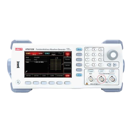
2.3 Panels and Buttons 2.3.1 Front Panel UTG2000B series provides users with a simple, intuitive, and easy to operate front panel. The front panel is shown in figure 2-1: USB port ON/OFF Display Screen Main Menu Button Secondary Menu Button Utility and setting Number buttons Manual trigger... -
Page 13: Rear Panel
● Setting amplitude>100mVpp, input voltage>±12.0V, frequency <10 kHz. ● Setting amplitude≤100mVpp, input voltage>±2.0V, frequency <10 kHz. “Overload protection, output off” appears when the protection is valid. 2.3.2 Rear Panel The rear panel is shown in figure 2-2: External analog modulation input connector External digital modulation/ frequency meter connector LAN port USB port... -
Page 14: Basic Waveform Output
Description: ● CH1/CH2: the selected channel will be highlighted. Limit indicates output range is at limit. White color: valid; Grey color: invalid. 50Ω indicates the matched impedance of output terminal (1Ω to 10KΩ adjustable, or high resistance; default:50Ω) sine wave. Different modes have different menu. ●... -
Page 15: Set Output Amplitude
2.4.2 Set output amplitude Default waveform: A sine wave of 100mV peak-peak value with 50Ω termination. Steps for setting the amplitude to 300mV: Press Menu → Wave → Param → Amp in turn. Press Vpp, Vrms, and dBm. Press number button to input 300. Press unit mVpp. -
Page 16: Set Square Wave
become high level (MAX) and low level (MIN). 2.4.4 Set square wave Default duty ratio: 50% limited by minimum pulse width 6.5ns. Steps to set a square wave with 1Hz, 1.5Vpp, DC offset 0V, duty ratio 70%: Press Menu → Wave → Type → Square → Param Enter required numerical value and select the unit. -
Page 17: Set Dc Offset Voltage
number and select unit. Note: This parameter can be set by multifunctional knob and direction buttons. 2.4.6 Set DC offset voltage Default DC voltage: 0V. Steps for setting DC offset voltage to 3V: Press Menu → Wave → Type → DC . If the current DC voltage is valid, adapt the same DC voltage value. -
Page 18: Set Noise Wave
ratio: Press Menu → Wave → Type → Ramp → Param Select the parameter to enter edit mode, then input required numbers and select unit. Note: When enter symmetry degree value, press 50% label at the bottom of the display. 2.4.8 Set noise wave Default noise: Gauss noise with amplitude 100mVpp and DC offset 0mV. -
Page 19: Set Expression
Press Menu → Wave → Type → Harmonic → Param in turn to enter parameter editing mode. After setting, enter number and unit. 2.4.10 Set expression Expression consists of number, operational character, class symbol (bracket), and free variables for the calculation of value, the permutation of which can represent the output waveform. - Page 20 18 types of operational functions are supported in this instrument. Expression enter into the expression editing interface, press Next to cycle switch operational symbol or expression. For example, input (x-1)*x(x+1), the interface is as below: The default initial value is 0°, end value is 180°, and expression is sin(x). The unit can be in rad or °. The setup procedures are as following: Press Menu Waveform...
-
Page 21: Set Utility
2.5 Set utility You can set channel information, sync output, merge channel, set up channel coupling, frequency meter, network, system, language, clock, load, save setting, arbitrary wave management, software upgrade, help, system information in Utility. 2.5.1 Set channel Menu Sub menu Setting Note Channel output... - Page 22 Channel output Select Channel output, you can select ON/OFF. Note: you can quickly turn on the channel output by pressing the CH1 or CH2 on the keypad. Channel reverse Select Channel reverse, you can select ON/OFF. Sync output Select Sync output, you can select “CH1”, “CH2” or “OFF”. Load Select Load, input range: 1Ω~1kΩ, you can also select 50Ω...
-
Page 23: Channel Coupling
Amplitude upper limit Select Amplitude upper limit, to set the limit value. Amplitude lower limit Select Amplitude lower limit, to set the limit value. 2.5.2 Channel coupling Menu Sub menu Setting Note Channel coupling ON/OFF ON/OFF Only when the status is ON, the following menu can be opened. -
Page 24: Frequency Meter
2.5.3 Frequency meter This instrument is able to measure the frequency and duty ratio of compatible TTL electric level signal. The range of measurement frequency is 100mHz~200MHz. When using the frequency meter function, the compatible TTL electric level signal is inputted through external digital modulation or frequency meter terminal (FSK Trig/CNT connector). -
Page 25: System
loaded automatically. Gateway Gateway format: nnn.nnn.nnn.nnn, range nnn: 0 to 255. It is suggested to ask the network administrator for an available Gateway. Select Gateway, use the keypad or the dial to input Gateway. Save this setting. When starting the instrument next time, the setting will be loaded automatically. - Page 26 Press Clock source to select internal or external. Internal: Provide 10MHz clock source. External:Receive external clock signal through【10MHz In】 (Requirement:Frequency: 10MHz, amplitude is TTL electric level). If there is no detected valid external clock source, a prompt will pop up stating that “External 10MHz clock invalid” with symbol appears at the lower left corner.
- Page 27 Support U disk firmware upgrade, procedures are as following: a. Copy and paste the *.bin file to U disk b. Insert the U disk to the USB Host port, when the symbol appears on the lower left corner of the display indicating U disk connected. c.
-
Page 28: Chapter 3 Advanced Applications
Chapter 3 Advanced Applications 3.1 Generate Modulation Waveform 3.1.1 Amplitude Modulation (AM) In AM modulation, modulated waveform is usually composed of carrier wave and modulation wave. The modulation of CH1 and CH2 is independent, you can set up the same or different mode for them. - Page 29 Set Carrier Wave Frequency Default frequency is 1kHz.Different carrier waveform has different settable frequency range. Press Param → Freq , enter value and select the unit. Carrier Wave Frequency UTG2122B UTG2082B UTG2062B Minimum Maximum Minimum Maximum Minimum Maximum Value Value...
- Page 30 arbitrary wave and noise. If need to change the waveform, press Param → ModWave . ● Square wave: duty ratio is 50% ● Rising Ramp Wave: symmetry degree is 100% ● Falling Ramp Wave: symmetry degree is 0% ● Arbitrary Wave: when arbitrary wave is modulated waveform, DDS function generator limits arbitrary wave length as 4kpts External Source When modulation source is external, parameter list will hide the modulation wave option and...
- Page 31 Set Modulation Signal Parameter After enabling the AM function, press Param soft key and the interface will appear as following: Press corresponding soft key, then enter required numerical value, and select the unit. Set Carrier Wave Signal Parameter UTG2000B Series...
- Page 32 Press Carrier → Type → Square in turn to select square wave as carrier wave signal. Press Param soft key again, and the interface will pop up as following: Press corresponding soft key, then enter required numerical value, and select the unit. Set Modulation Depth UTG2000B Series...
- Page 33 After setting carrier wave parameter, press Return soft key to back to the following interface for setting modulation depth. Press Param → depth soft key again, then enter number 80 and press % soft key with number keyboard for setting modulation depth. Enable Channel Output Press CH1 button start channel 1 output quickly.
-
Page 34: Frequency Modulation (Fm)
The shape of AM modulation waveform checked through oscilloscope is shown as following: 3.1.2 Frequency Modulation (FM) In frequency modulation, modulated waveform is usually composed of carrier wave and modulation wave. Carrier wave frequency will change as the amplitude of modulation wave changes. Press Menu →... - Page 35 Carrier Wave Waveform Selection FM carrier waveform can be: Sine wave, square wave, ramp wave, pulse wave, arbitrary wave (except DC) and noise (the default is sine wave). After selecting FM modulation, press Carrier soft key to enter carrier waveform selection interface. Carrier Wave Waveform FM wave waveform: sine wave, square wave, ramp wave, or arbitrary wave(exp.
- Page 36 If you need to set up the carrier wave frequency,see Carrier Wave Frequency Setting Modulation Source Selection This device can select internal modulation source or external modulation source. After enabling FM function, the default of modulation source is internal. If need to change, press param → Source →...
- Page 37 more than carrier wave frequency, while in negative signal level, FM output frequency is less than carrier wave frequency. Low external signal level has small deviation. For example, if the frequency offset is set to 1kHz and the external modulation signal is +5V, FM output frequency will be the current carrier frequency plus 1kHz.
- Page 38 Set Modulation Signal Parameter Press Param soft key. Then the interface will show as following: Press corresponding soft key, then enter required numerical value, and select the unit. Set Carrier Wave Signal Parameter UTG2000B Series...
- Page 39 Press Carrier → Type → Sine in turn to select sine wave as carrier wave signal. Press Param soft key, and the interface will pop up as following: Press corresponding soft key first, then enter required numerical value, and select the unit. Set Frequency Deviation UTG2000B Series...
- Page 40 After setting carrier wave parameter, press Return soft key to back to the following interface for setting frequency deviation. Press Param → FreDev soft key, then enter number 5 and press kHz soft key with number keyboard for setting frequency deviation. Press CH1 button start channel 1 output quickly.
-
Page 41: Phase Modulation (Pm)
The shape of FM modulation waveform checked through oscilloscope is shown as following: 3.1.3 Phase Modulation (PM) In phase modulation, modulated waveform is usually composed of carrier wave and modulation wave. The modulation of CH1 and CH2 is independent, you can set up the same or different mode for them. - Page 42 Carrier Wave Waveform Selection PM carrier waveform can be: Sine wave, square wave, ramp wave or arbitrary wave (except DC), and the default is sine wave. Press Carrier soft key to select carrier waveform. Carrier Wave Frequency Setting If you need to set up the carrier wave frequency,see Carrier Wave Frequency Setting Modulation Source Selection This device can select internal modulation source or external modulation source.
- Page 43 Internal Source When modulation source is internal, modulation wave can be: sine wave, square wave, rising ramp wave, falling ramp wave, arbitrary wave and noise.After enabling FM function, the default of modulation wave is sine wave. If need to change, press Param → ModWave in turn. ●...
- Page 44 Enable Phase Modulation (PM) Function Press Menu → Mod → Type → PM in turn to start the PM function. Set Modulation Signal Parameter Press Param soft key and the interface will show as following: Press corresponding soft key first, then enter required numerical value, and select the unit. UTG2000B Series...
- Page 45 Set Carrier Wave Signal Parameter Press Carrier → Type → Sine in turn to select sine wave as carrier wave signal. Press Param soft key, and the interface will pop up as following: Press corresponding soft key, then enter required numerical value, and select the unit. UTG2000B Series...
- Page 46 Set Phase Deviation Press Return soft key to back to the following interface for setting phase modulation. Press Param → PhaseDev soft key, then enter number 200 and press ˚ soft key with number keyboard for setting phase deviation. UTG2000B Series...
- Page 47 Enable Channel Output Press CH1 button start channel 1 output quickly. Or enable output by pressing Utility and then CH1 Setting . After channel output is opened, backlight of CH1 button is on, and on the right side of channel information label, the font “OFF” changes to “PM”, meaning open channel output. The shape of PM modulation waveform checked through oscilloscope is shown as following: UTG2000B Series...
-
Page 48: Amplitude Shift Keying (Ask)
3.1.4 Amplitude Shift Keying (ASK) ASK shows digital signal “0” and “1” by changing amplitude of carrier wave signal. Carrier wave signal with different amplitude will be output on the basis of different logic of modulation signal. ASK Modulation Selection Press Menu →... - Page 49 Carrier Wave Frequency Setting See Carrier Wave Frequency Setting Modulation Source Selection The device can select internal modulation source or external modulation source. After enabling ASK function, the default of modulation source is internal. If need to change, press Param → Source →...
- Page 50 Set Carrier Wave Signal Parameter Press Carrier → Type → Sine in turn Press Param soft key, and the interface will pop up as following: Press corresponding soft key, then enter required numerical value, and select the unit. UTG2000B Series...
- Page 51 Set ASK Rate After setting carrier wave parameter, press Return soft key to go back to the following interface for setting phase modulation. Press Param → Rate soft key again, then enter number 300 and press Hz soft key with number keyboard for setting ASK rate.
- Page 52 Enable Channel Output Press CH1 button start channel 1 output quickly. Or enable output by pressing Utility and then CH1 Setting. After channel output is opened, backlight of CH1 button is on, and on the right side of channel information label, the font “OFF” changes to “ASK”, meaning open channel output. The shape of ASK modulation waveform checked through oscilloscope is shown as following: UTG2000B Series...
-
Page 53: Frequency Shift Keying (Fsk)
3.1.5 Frequency Shift Keying (FSK) In frequency shift keying, rate of carrier wave frequency and hopping frequency can be changed. FSK Modulation Selection Press Menu → Mod → Type → FSK in turn to start the FSK function. The device will output modulated waveform with current setting. - Page 54 Carrier Wave Frequency Setting See Carrier Wave Frequency Setting Modulation Source Selection The device can select internal modulation source or external modulation source. After enabling FSK function, the default of modulation source is internal. If need to change, press Param → Source → External in turn.
- Page 55 Hop Frequency Setting After enabling FSK function, the default of hop frequency is 2MHz. If need to change, press Param → HopFreq in turn. Settable range of hop frequency is determined by carrier wave waveform. See Carrier Wave Frequency Setting FSK Rate Setting When modulation source is internal, the moving frequency between carrier wave frequency and hop frequency can be set.
- Page 56 Press Param soft key again, and the interface will pop up as following Press corresponding soft key first, then enter required numerical value, and select the unit. Set Hop Frequency and FSK Rate Press Return soft key to go back to the following interface. UTG2000B Series...
- Page 57 Press Param soft key again, and the interface will pop up as following Press corresponding soft key first, then enter required numerical value, and select the unit. Enable Channel Output Press CH1 button start channel 1 output quickly. Or enable output by pressing Utility and then CH1 UTG2000B Series...
-
Page 58: Phase Shift Keying (Psk)
Setting . After channel output is opened, backlight of CH1 button is on, and on the right side of channel information label, the font “OFF” changes to “FSK”, meaning open channel output. The shape of FSK modulation waveform checked through oscilloscope is shown as following: 3.1.6 Phase Shift Keying (PSK) In phase shift keying, DDS function generator can be configured to move between two preset phase (carrier wave phase and modulation phase). - Page 59 Carrier Wave Waveform Selection PSK carrier waveform can be: Sine wave, square, ramp wave or arbitrary wave (except DC), and the default is sine wave. Press Carrier soft key to enter carrier waveform selection interface. Carrier Wave Frequency Setting See Carrier Wave Frequency Setting Modulation Source Selection UTG2000B function/arbitrary waveform generator can select internal modulation source or external modulation source.
- Page 60 Internal Source When modulation source is internal, internal modulation wave is a square wave of 50% duty ratio (not adjustable). The PSK rate can be set to customize the moving frequency between carrier wave phase and modulation phase. External Source When modulation source is external, carrier waveform will be modulated by an external waveform.
- Page 61 Set Carrier Wave Signal Parameter Press Carrier → Type → Sine in turn to select sine wave as carrier wave signal. Press Param soft key, and the interface will pop up as following: Press corresponding soft key, then enter required numerical value, and select the unit. UTG2000B Series...
- Page 62 Set PSK Rate and Modulation Phase Press Return soft key to go back to the following interface: Press Param soft key, and the interface will pop up as following: Press corresponding soft key, then enter required numerical value, and select the unit. UTG2000B Series...
- Page 63 Enable Channel Output Press CH1 button start channel 1 output quickly. Or enable output by pressing Utility and then CH1 Setting . After channel output is opened, backlight of CH1 button is on, and on the right side of channel information label, the font “OFF”...
-
Page 64: Binary Phase Shift Keying (Bpsk)
3.1.7 Binary Phase Shift Keying (BPSK) The function/arbitrary waveform generator can move between two preset phases (carrier phase and modulation phase) in binary phase shift keying, expressing 0 and 1. Phase of carrier signal or modulation signal is output according to logic of modulation signal. The modulation mode of the two channels is mutually independent. - Page 65 Set carrier frequency See Carrier Frequency Wave Setting Select modulation source UTG2000B function/arbitrary waveform generator can select internal or external modulation source. After you enable BPSK function, you can see that modulation source is PN7 by default. You can change it with multi-functional knob on the interface for using PSK function or by pressing soft key Param →...
- Page 66 First make the instrument run in BPSK mode, and then set an internal sine wave of 2kHz and 2Vpp as carrier signal. Finally set carrier phase and initial modulation phase to be 90 ˚, frequency between phases to be 1kHz and PN code to be PN15. The specific steps are as follows: Use BPSK function Press s Menu →...
- Page 67 If you need to set up the parameter, input the value and then select the unit. Set BPSK rate, modulation phase and PN code Press Return to return to the interface below after setting carrier parameters: To set some parameter, press corresponding soft key, input the required value and select the unit. UTG2000B Series...
- Page 68 Enable channel output Press CH1 button start channel 1 output quickly. Or enable output by pressing Utility and then CH1 Setting . After channel output is opened, backlight of CH1 button is on, and on the right side of channel information label, the font “OFF”...
-
Page 69: Quadrature Phase Shift Keying(Qpsk)
3.1.8 Quadrature Phase Shift Keying(QPSK) The function/arbitrary waveform generator can move between four preset phases (carrier phase and 3 modulation phases). Phase of carrier signal or modulation signal is output according to logic of modulation signal. The modulation mode of the two channels is mutually independent. You can configure same or different modulation mode for channel 1 and 2. -
Page 70: Oscillation Keying(Osk)
3.1.9 Oscillation Keying(OSK) The function/arbitrary waveform generator can output a sinusoidal signal of intermittent oscillation in OSK. Carrier waveform is output when internal crystal oscillator starts oscillation; output is stopped when internal crystal oscillator stops oscillation. The modulation mode of the two channels is mutually independent. - Page 71 you use PSK function, you can see that modulation source is internal by default. You can change it with multi-functional knob on the interface for using PSK function or by pressing Param → Source Internal source In case of internal modulation source, internal modulation wave is sine wave. The phase relation between oscillation start and stop can be designated by setting OSK rate.
- Page 72 (2) Set carrier signal parameters Press Carrier → Type → Sine to select carrier signal as sine wave. The default carrier signal is sine wave, so it is unnecessary to change in this example. You can set with multi-functional knob and direction key.
- Page 73 You can set with multi-functional knob and direction key directly on this interface. You can also press corresponding soft keys of function again, when the interface below will pop up. To set some parameter, press corresponding soft key, input the required value and select the unit. Figure 3 - 2 Set modulation rate Use channel output Press CH1 button start channel 1 output quickly.
-
Page 74: Sum Modulation(Sum)
Figure 3 - 3 Use channel output Check the shape of OSK modulation waveform through oscilloscope, which is shown in the figure below: Figure 3 - 4 OSK waveform with oscilloscope 3.1.10 Sum Modulation(SUM) In SUM, the modulated waveform generally is composed of carrier wave and modulation wave. The output waveform is obtained by the sum of product of carrier amplitude and modulation factor and product of amplitude of modulation wave and modulation factor. - Page 75 Figure 3 - 5 Select SUM function Select carrier waveform SUM carrier waveform can be sine wave, square wave, ramp wave or arbitrary wave (except DC), and is sine wave by default. After SUM is selected, press the key of basic waveform setting to quickly set corresponding carrier waveform.
- Page 76 ● ModWave Square wave: duty ratio is 50% ● Rising ramp wave: symmetry degree is 100% ● Falling ramp wave: symmetry degree is 0% ● Arbitrary wave: when selecting arbitrary wave as modulation waveform, function/arbitrary waveform generator limits length of arbitrary wave to 4kpts by automatic test count. Noise: white ●...
- Page 77 Figure 3 - 7 Select SUM function (2) Select carrier waveform After enabling SUM function, press Carrier → Type → Square . You can press Param again until the following interface appears. Figure 3 - 8 Set modulation parameter (3) Set FSK rate and modulation phase After setting up, press Return to turn to the interface below: 4)Use channel output Press CH1 button start channel 1 output quickly.
- Page 78 (4) Use channel output Press CH1 button start channel 1 output quickly. Or enable output by pressing Utility and then CH1 Setting . After channel output is opened, backlight of CH1 button is on, and on the right side of channel information label, the font “OFF”...
-
Page 79: Double Side Band Amplitude Modulation (Dsbam)
3.1.11 Double side band amplitude Modulation (DSBAM) Select carrier waveform DSBAM carrier waveform can be sine wave, square wave, ramp wave or arbitrary wave (except DC), and is sine wave by default. After DSBAM is selected, press the key of basic waveform setting to quickly set corresponding carrier waveform. - Page 80 Figure 3 - 10 Select modulation source Internal source In case of internal modulation source, modulation wave can be sine wave, square wave, rising ramp wave, falling ramp wave, arbitrary wave and noise, and is sine wave by default. After you use DSBAM function, you can see that modulation wave is sine wave by default.
- Page 81 Press Mod → Type → DSBAM (press soft key Type to select if Type is not highlighted). Set carrier waveform parameters Press Param → Type → Sine (if TYPE is not highlighted, press TYPE) You can use the multifunctional knob and soft keys to set the parameters. After you press Param , the following interface will be displayed: UTG2000B Series...
- Page 82 Input the number and select the unit. Set DSBAM rate and modulation phase After setting up, press Return to turn to the interface below: UTG2000B Series...
-
Page 83: Quadrature Amplitude Modulation(Qam)
Use channel output Press CH1 button start channel 1 output quickly. Or enable output by pressing Utility and then CH1 Setting . After channel output is opened, backlight of CH1 button is on, and on the right side of channel information label, the font “OFF” changes to “DSBAM”, meaning open channel output. - Page 84 reference clock input for demodulation devices. Select QAM Press Menu → Mod → Type → QAM successively to use QAM function (if Type is not highlighted, press soft key Type to select). After QAM function is used, UTG2000B function/arbitrary waveform generator will output modulated waveform with the current carrier phase and modulation phase.
- Page 85 number, you can set as PN7,PN9,PN11,PN15,PN17,21,PN23,PN25 Set QAM rate After you use QAM function, you can set QAM rate, which is in the range of 2mHz~1MHz and 100Hz by default. You can change it with multi-functional knob and direction key on the interface for using ASK function or by pressing Param →...
- Page 86 Enable channel output Press CH1 button start channel 1 output quickly. Or enable output by pressing Utility and then CH1 Setting . After channel output is opened, backlight of CH1 button is on, and on the right side of channel information label, the font “OFF” changes to “QAM”, meaning open channel output. Check the shape of QAM modulation waveform through oscilloscope, which is shown in the figure below: UTG2000B Series...
-
Page 87: Pulse Width Modulation (Pwm)
Figure 3 -19 Observe QAM waveform with oscilloscope 3.1.13 Pulse Width Modulation (PWM) In PWM, modulated waveform generally is composed of carrier wave and modulation wave. The pulse width of carrier wave will vary with the amplitude of modulation wave. The modulation mode of the two channels is mutually independent. - Page 88 Figure 3 - 21 Set carrier waveform Set carrier frequency See Carrier Frequency Wave Setting The frequency range of pulse wave is 1μH~30MHz. Default frequency is 1kHz. To set carrier frequency, please use multi-functional knob and direction key in the interface or press soft function key Param →...
- Page 89 In case of internal modulation source, modulation wave can be sine wave, square wave, rising ramp wave, falling ramp wave, arbitrary wave and noise, and is sine wave by default. After you use PWM function, you can see that modulation wave is sine wave by default. You can change it with multi-functional knob on interface for using PWM function or by pressing Param →...
- Page 90 Figure 3 -23 Select PWM function Set modulation signal parameters Set with multi-functional knob and direction key after using PWM function. You can also press corresponding soft keys of function on the above interface for using PWM function, when the interface below will pop up.
- Page 91 Figure 3 -25 Set carrier parameters You can set with multi-functional knob and direction key. You can also press corresponding soft keys of function again, when the interface below will pop up. To set some parameter, press corresponding soft key, input the required value and select the unit. Figure 3 - 26 Set rising edge Set duty ratio deviation Press Return to return to the interface below to set frequency deviation after setting carrier...
- Page 92 Figure 3 - 27 Set modulation parameters You can set with multi-functional knob and direction key. You can also press soft function key Param → DutyDev again, input the number 40 through numeric keyboard and press soft key % to set duty ratio deviation.
-
Page 93: Output Frequency Sweep Waveform
Check the shape of PWM modulation waveform through oscilloscope, which is shown in the figure below: Figure 3 - 30 Observe PWM waveform with oscilloscope 3.2 Output Frequency Sweep Waveform When selecting frequency sweep mode, the output frequency of function/arbitrary waveform generator changes in a linear or logarithmic way from starting frequency to stop frequency in designated frequency sweep time. -
Page 94: Set Starting And Stop Frequency
setting. Figure 3 -31 Select SWEEP function Select frequency sweep waveform After frequency sweep is started, press Carrier to select frequency sweep waveform. The interface that pops up is shown in the figure below: Figure 3 - 32 Select frequency sweep waveform 3.2.2 Set Starting and Stop Frequency Starting frequency and stop frequency are upper limit and lower limit of frequency sweep. -
Page 95: Frequency Sweep Mode
By default, starting frequency is 1kHz and stop frequency is 2kHz, but the range of starting and stop frequency can vary with frequency sweep waveform. See the table below for the frequency range of frequency sweep wave: Table 3 - 4 Frequency UTG2122B UTG2082B UTG2062B Carrier waveform 1µHz... -
Page 96: Frequency Sweep Time
Figure 3 - 35 Select logarithmic frequency sweep 3.2.4 Frequency Sweep Time Set the time from starting frequency to stop frequency, which is 1s by default and in the range of 1ms~500s. To change it, you can use multi-functional knob and direction key on the interface for selecting frequency sweep mode or press soft function key Param →... -
Page 97: Trigger Output
In case of internal trigger, waveform generator will output continuous frequency sweep, the rate of which is determined by frequency sweep time. In case of external trigger, waveform generator will accept a hardware trigger that has been applied to external digital modulation interface (FSK Trig connector)of back panel. The waveform generator will start frequency sweep upon receiving a TTL pulse with designated polarity. -
Page 98: Trigger Edge
interface for selecting frequency sweep mode or press Page Up/Down and soft function key Param → TrigOut → On successively. ● In internal trigger, signal generator outputs a square wave with duty ratio of 50% from external digital modulation interface (FSK Trig connector) when frequency sweep starts. Trigger period depends on designated frequency sweep time. - Page 99 Figure 3 -39 Select SWEEP function 1) Select frequency sweep waveform After linear frequency sweep function is used, press Carrier → Type → Square to select frequency sweep waveform, when the interface below will pop up: Figure 3 - 40 Select frequency sweep waveform You can set amplitude with multi-functional knob and direction key.
- Page 100 Figure 3 -42 Set frequency sweep parameters You can set with multi-functional knob and direction key. You can also press corresponding soft function keys again, when the interface below will pop up. To set some parameter, press Param , input the required value and select the unit. Figure 3 - 43 Set trigger frequency Enable channel output Press CH1 button start channel 1 output quickly.
-
Page 101: Output Burst
Check the shape of frequency sweep waveform through oscilloscope, which is shown in the figure below: 3.3 Output Burst Signal generator can create a waveform with designated recurring number (known as pulse train). UTG2000B supports control of pulse train output with internal, external or manual trigger, and three types of pulse train, including N cycle, gating and infinite. - Page 102 Figure 3 -46 Select BURST function 2) Select waveform ● N cycle mode supports sine wave, square wave, ramp wave, pulse wave and arbitrary wave (except DC). ● Gating mode supports sine wave, square wave, ramp wave, pulse wave, arbitrary wave (except DC) and noise.
-
Page 103: Type Of Burst
Table 3 -5 Frequency UTG2122B UTG2082B UTG2062B Carrier waveform 1µHz Sine 120MHz 80MHz 60MHz 1µHz 1µHz Square 1µHz 30MHz 25MHz 25MHz 1µHz 1µHz Ramp 1µHz 5MHz 4MHz 3MHz 1µHz 1µHz 1µHz Pulse 30MHz 25MHz 25MHz 1µHz 1µHz... -
Page 104: Gating Mode
3.3.3 Gating mode Press soft function keys Type → Gated successively on the interface to enter gating mode. In mode of gating pulse train, trigger source, trigger output, trigger edge, burst period (period of pulse train) and recurring number will be automatically hidden in parameter list. As only external trigger source can be used, waveform generator is triggered according to hardware of external digital modulation interface (FSK Trig connector) of back panel. -
Page 105: Phase Of Burst
3.3.4 Phase of Burst Phase of pulse train is phase at starting point of pulse train. It is in the range of 0°~+360°. The default initial phase is 0°. To change it, you can use multi-functional knob and direction key on the interface for selecting type of pulse train or press soft function key Param →... -
Page 106: Counting Of Burst
(period of pulse train) will be hidden in parameter list. The range of burst period (period of pulse train) is 1µs~500s; the default “burst period” is 1ms.To change it, you can use multi-functional knob and direction key or press soft key Param → Period after selecting type of pulse train as N cycle. -
Page 107: Trigger Edge
● Manual trigger: the instrument outputs pulse with over 1us pulse width from the beginning of pulse train. ● External trigger: the menu will hide the trigger output option which is enabled by external modulation connector (FSK Trig connector). This connector should not be used as external and internal at the same time. - Page 108 Figure 3 -53 Select waveform of pulse train You can set amplitude with multi-functional knob and direction key (note: if frequency is displayed, only frequency can be set, which means that conversion between frequency and period cannot be realized. If frequency is displayed, period of 2ms is corresponding to frequency of 500Hz. They are reciprocal, i.e.
- Page 109 Figure 3 - 55 Set pulse train parameters You can set with multi-functional knob and direction key. You can also press corresponding soft keys of parameters again, when the interface below will pop up. To set some parameter, press corresponding soft key, input the required value and select the unit. Figure 3 - 56 Set period of pulse train Enable channel output Press CH1 button start channel 1 output quickly.
-
Page 110: Output Arbitrary Wave
Figure 3 - 57 Use channel output Check the shape of pulse train through oscilloscope, which is shown in the figure below: Figure 3 -58 Observe BURST waveform with oscilloscope 3.4 Output Arbitrary Wave UTG2000B stores 160 types of standard waveform in nonvolatile storage. See Table 3 -4 (list of built-in arbitrary wave) for the name of waveform. -
Page 111: Point-By-Point Output/Play Mode
Figure 3 -59 Select Arb function 3.4.2 Point-by-point Output/Play Mode UTG2000B supports point-by-point output of arbitrary waveform. In point-by-point output mode, signal generator automatically calculates frequency of output signal (4882.81250Hz) according to waveform length (e.g. 65536 points) and sampling rate. The signal generator outputs waveform points one by one with this frequency. -
Page 112: Select Arbitrary Wave
3.4.3 Select Arbitrary Wave UTG2000B allows users to output arbitrary waveform in internal or external storage of the instrument. You can select the arbitrary wave you need with multi-functional knob and direction key on the interface for using arbitrary wave function or by pressing soft keys Param →... - Page 113 Hemispheric wave RoundHalf RoundsPM RoundsPM waveform Step response signal StepResp SwingOsc Swing oscillation function- time curve TV signal Voice signal Voice Airy Airy function Besselj Class-I Bessel function Besselk Besselk function Bessely Class-II Bessel function Cauchy Cauchy distribution Cubic Cubic function Dirichlet Dirichlet function Error function...
- Page 114 types) Tens3 Transcutaneous electric nerve stimulation waveform 3 Ignition Ignition waveform of automobile internal-combustion engine Automobile starting sectional drawing with oscillation ISO16750-2 SP ISO16750-2 Starting1 Automobile voltage waveform caused by start-up1 ISO16750-2 Starting2 Automobile voltage waveform caused by start-up 2 ISO16750-2 Starting3 Automobile voltage waveform caused by start-up 3 ISO16750-2 Starting4 Automobile voltage waveform caused by start-up 4 Sectional drawing of automobile working voltage in...
- Page 115 Hyperbolic tangent TanH Acos Arc-cosine function Arc- hyperbolic cosine function ACosH Concave arc cotangent function ACotCon Convex arc cotangent function ACotPro Concave arc- hyperbolic cosine function ACotHCon Convex arc- hyperbolic cosine function ACotHPro ACscCon Concave arc cosecant function ACscPro Convex arc cosecant function Concave arc hyperbolic cosecant function ACscHCon Convex arc hyperbolic cosecant function...
-
Page 116: Create And Edit Arbitrary Waveform
3.4.4 Create and Edit Arbitrary Waveform UTG2000B creates and edits complicated arbitrary waveform (of any amplitude and shape) through powerful upper computer software. Please see Operation Manual of UTG2000B Arbitrary Waveform Editing Software for specific operation. UTG2000B Series... -
Page 117: Chapter 4 Fault Handling
Chapter 4 Fault Handling Possible faults in use of UTG2000B and troubleshooting methods are listed below. If these faults occur, please handle them according to corresponding steps. If they cannot be handled, please contact with the dealer or local office, and provide the information about your machine (method: press Utility →... -
Page 118: Chapter 5 Service And Support
UNI-T (Uni-Trend Technology (China) Limited) guarantees that the products it produces and sells are free from any defects of material and process within 3 years from authorizing the dealer to deliver them. If the product is proven to be defective during warranty period, UNI-T will repair and replace according to provisions of warranty. -
Page 119: Appendix A: Factory Reset State
Appendix A: Factory Reset State Factory default Parameter Channel parameter Current carrier wave Sine wave Output load 50Ω Sync output Channel 1 Channel output Channel output opposition Amplitude limit Upper amplitude limit Lower amplitude limit Fundamental wave Frequency 1kHz Amplitude 100mVpp DC offset Initial phase... - Page 120 Modulation source Internal FSK rate 100Hz Hopping frequency 2MHz PSK modulation Modulation source Internal PSK rate 100Hz PSK phase 0° BPSK modulation Carrier wave Sine PN7,PN9,PN11,PN15,PN17,PN21,PN23,PN25 Modulation source Phase 0° Phase 1 180° Coding mode PN15 BPSK rate 100Hz QPSK modulation Carrier wave Sine PN7,PN9,PN11,PN15,PN17,PN21,PN23,PN25...
- Page 121 Burst period (period of pulse train) 1.0001ms Recurring number Gated polarity Positive polarity Trigger source Internal Trigger output Trigger edge Rising edge System parameter IP type DHCP Clock source Internal Clock output Sound of buzzer Separator of numbers Backlight 100% Language * Depend on factory setting UTG2000B Series...
-
Page 122: Appendix B: Performance Index
Appendix B: Performance Index Model UTG2122B UTG2082B UTG2062B Channel Dual channel Max frequency 120MHz 80MHz 60MHz Sampling rate 1.28GSa/s (320MSa/s ,4 times interpolation) Sine, square, ramp, burst, noise, DC, arbitrary, harmonic, expression Waveform Working modes Output gating, continuous, modulation, frequency sweep, burst AM、FM、PM、ASK、FSK、PSK、BPSK、QPSK、... - Page 123 Symmetry 0.0% ~ 100.0% Impulse wave Frequency 1μHz~30MHz 1μHz~25MHz 1μHz~25MHz resolution 1uHz ≥16ns pulse width variable edge 7ns~10s 8ns~10s 9ns~10s <2% (typical 1Vpp) overshoot 150ps shake Gauss noise 120MHz(-3dB)(typical) 80MHz(-3dB)(typical) 60MHz(-3dB)(typical) Bandwidth ± 5V(50Ω) DC offset range(peak AC+DC) ±10V (high resistance) offset accuracy ±(1%+2mV) Arbitrary wave...
- Page 124 modulation frequency 2mHz~1MHz Modulation depth 0%~120% Sine wave, square wave(1μHz~30MHz), ramp wave, arbitrary wave Carrier wave Source Internal/external Sine wave, square wave, ramp wave, noise, arbitrary wave Modulation wave Modulation frequency 2mHz~1MHz Frequency deviation DC ~60MHz DC ~40MHz DC ~30MHz Sine wave, square wave(1μHz~30MHz), ramp wave, arbitrary wave Carrier wave Source...
- Page 125 Sine wave, square wave(1μHz~30MHz), ramp wave, Modulation wave noise wave, arbitrary wave 2mHz ~ 1MHz (internal);DC ~ 20kHz (external) Modulation frequency QAM4,QAM8,QAM16,QAM32,QAM64,QAM128,QAM256 QAM mode (built-in constellation modulation) PN7,PN9,PN11,PN15,PN17,PN21,PN23,PN25 Modulation source Chip rate 2mHz~1MHz Amplitude 10mVpp~10Vpp(50Ω) Carrier wave Pulse Source Internal/external Sine wave, square wave, ramp wave, noise, arbitrary wave Modulation wave modulation frequency...
- Page 126 Trigger input Input level TTL compatible Slope Rising or falling, optional Pulse width > 100 ns Input impedance > 10kΩ,DC coupling Frequency sweep:< 500μs,typical value Pulse train:< 500ns,typical value Response time Trigger output TTL compatible Level > 400ns,typical value Pulse width Output impedance 50Ω,typical value Maximum frequency...
-
Page 127: Appendix C: List Of Accessories
Appendix C: List of Accessories UTG2000B(dual channel) Model A power line up to local standard A USB data line One BNC cables (1 m),One BNC+red and black alligator clip connection(1 m) Standard configuration A CD for users A product warranty card A user manual Optional components Power output module... -
Page 128: Appendix D: Maintenance And Cleaning
Appendix D: Maintenance and Cleaning General maintenance ● Please don’t store or place the instrument where LCD is exposed to direct sunlight for a long time. ● To avoid damage to the instrument or connecting line, please don’t place it in mist, liquid or solvent. - Page 129 This user manual may be revised without prior notice UTG2000B Series...
- Page 130 UTG2000B Series...