Table of Contents
Advertisement
Quick Links
Advertisement
Table of Contents

Related Manuals for Wahl TM602


Summary of Contents for Wahl TM602
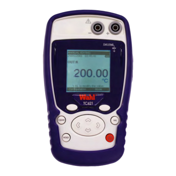
- Page 1 Pocket RTD and Thermocouple Temperature Meters and Calibrators TM602 • TM612(A) • TM630(A) TC621 • TC622(A) User Manual Palmer Wahl 234 Old Weaverville Road Asheville, NC 28804 Toll Free 800-421-2853 Phone 828-658-3131 Fax 828-658-0728 WD1017 Rev E www.palmerwahl.com Revised 01/26/23...
- Page 2 Manufacturer. In addition, if the product is tampered with in any way or calibrated in any way other than by the instructions supplied by Palmer Wahl, it will immediately void the warranty.
- Page 3 Product Verification Each TC6XX-TM6XX unit has been checked mechanically and electrically prior to delivery. The necessary precautions have been taken to ensure it reaches the user without being damaged. Nonetheless, it is wise to perform a rapid check for any damage which may have occurred during transport. If this is the case, inform the carrier immediately.
-
Page 4: Table Of Contents
Software Update ................................39 Technical specifications ..............................40 Thermocouple measurement function ........................40 G.1.1 Constant voltage (TC621,TM602 and TM630).....................40 G.1.2 Temperature by thermocouples (TC621,TM602 et TM630)................40 Thermocouple emission function (TC621) .........................42 G.2.1 Constant voltage ..............................42 G.2.2 Temperature by thermocouple ..........................42 Resistive sensor measurement function ........................44 G.3.1... -
Page 5: General
Introduction A. GENERAL Introduction The TC6XX-TM6XX Series range is made of 5 temperature measurement and/or calibration devices for thermocouples and resistive sensors. They are especially designed for calibration and maintenance. It makes it possible to measure and to emit electrical measurements and to simulate temperatures both on site as well as in a laboratory. The TC6XX-TM6XX Series range features a large number of related functions which extend its range of application, including: Generation of default values, increases, single or cyclic ramps (for TC621 and TC622). -
Page 6: Directives Ce
TC6XX-TM6XX Series GENERAL Directives CE A.4.1 Conformity with standards The device complies with the applicable directives in force on the subject of electrical safety (2006/95/CE) as well as on the electromagnetic compatibility of the electrical measuring instruments (2004/108/CE). These instructions for use contain information and warnings which must be observed by the user to protect the latter against the dangers of electricity, to ensure the safe operation of the device and to protect it against any mishandling which could damage or compromise the safety of use of the device. -
Page 7: Making Measurements
Directives CE A.4.5 Making measurements Measuring wires and leads must be in good condition and must be replaced if their insulation appears defective (insulation cut, burned, etc.). Never exceed the protection value limits indicated in the specifications. Before changing function, disconnect the measuring wires from the external circuit. When voltage measurements are being made, even weak ones, keep in mind that the circuits may feature a dangerous voltage for the operator compared to the ground. -
Page 8: Maintenance
TC6XX-TM6XX Series GENERAL Maintenance The unit must always be set up according to the instructions in this notice. Any incomplete or poorly executed set up may compromise the safety of the operator. The responsible authority must ensure on a regular basis that factors affecting safety do not change with time and carry out any necessary preventive work. -
Page 9: Using The Instrument
Power-up B. USING THE INSTRUMENT In order to use the device with all the safety requirements, all operators must read the paragraph on safety carefully, along with the paragraph below. Power-up B.1.1 Battery replacement The instrument is supplied with four 1.5V AA batteries. The batteries must be installed in the battery compartment in the back of the instrument. -
Page 10: The Measuring And Simulation Terminals For Each Device
The measuring and simulation terminals for each device Both the TC621 and TM602 are fitted with 2 safety bushes (4 mm in diameter) and a miniature flat plug for thermocouples. These connector assemblies are used both in measurement and emission modes (non simultaneous). - Page 11 Power-up 3-wire voltage / measurement terminal Measurement: Current terminal (positive) Simulation: Current terminal (negative) Measurement: Current terminal (negative) 4-wire voltage Simulation: measurement terminal Current terminal (Positive) Measurement: Measurement: Current terminal (positive) Current terminal (negative) 4-wire voltage measurement terminal 3-wire voltage measurement terminal Remark: When using the unit with resistance testers/simulators, make sure polarities are observed.
-
Page 12: The Usb Connector
TC6XX-TM6XX Series USING THE INSTRUMENT B.1.5 The USB connector The TC6XX-TM6XX Series range is fitted with a USB connector (mini B) intended for uploading new software versions and device adjustment. USB port (mini B connector) B.1.6 The screen The TC6XX-TM6XX Series range is fitted with a graphic LCD display with back-lighting. The display resolution is 160 x 160 pixels. -
Page 13: Operating Modes
Power-up Symbol Description Step increment transmission mode Single ramp signal transmission mode Cyclic ramp signal transmission mode Scaling On hold Filtering %FS (full scale) function Error (over-calibration in measurement or error on the value emitted…) Incremental mode using the arrows Battery life indication Acquisition in progress (the value on the right of the pictogram indicates the number of values recorded) - Page 14 TC6XX-TM6XX Series USING THE INSTRUMENT B.1.7.3 Electrical characteristics not to be exceeded for "voltage" gauges (TC621, TM630 and TM602) Function Gauge Max Vin Z load U measurement 100mV 60 V U emission (TC6621) 80mV 1000 min B.1.7.4 Resistances / temperature measurement (TC622, TM630 and TM612)
-
Page 15: Programming Mode
Voltage / resistance or temperature measurement C. PROGRAMMING MODES Voltage / resistance or temperature measurement The choice of measurement or emission mode is made using the F2 key (mode menu). Using the navigation keys ( and ), position the cursor in the Measurement field going down the menu. ... - Page 16 TC6XX-TM6XX Series PROGRAMMING MODES Attention, the choice of °C or °F is made in the Setup\Preferences\temp unit menu. Using the F1 key, define the CSF used by positioning the cursor on it (for TC621, TM602 and TM630 units only).
-
Page 17: Voltage / Resistance Or Temperature Simulation
Voltage / resistance or temperature simulation Voltage / resistance or temperature simulation To access the Emission mode: The choice of Emission mode is made using the F2 key (mode menu). Using the navigation keys ( and ), position the cursor in the Emission field going down the menu. ... - Page 18 TC6XX-TM6XX Series PROGRAMMING MODES Voltage / resistance or temperature generation / arrow editing? Press the F2 key to display the edit menu. Using the navigation keys ( and ), choose the Arrows edit mode and confirm (VAL key). ...
- Page 19 Voltage / resistance or temperature simulation Voltage / resistance or temperature generation / cyclic ramp editing? Press the F2 key to display the edit menu. Using the navigation keys ( and ), choose the CYCLIC RAMP mode and confirm (VAL key). ...
-
Page 20: Related Functions
TC6XX-TM6XX Series RELATED FUNCTIONS D. RELATED FUNCTIONS Scaling The scale correction function performs conversion operations between the electrical values measured and the physical values converted. This linearization operation makes it possible to correct partially the errors induced by non-linear sensor/converter systems. -
Page 21: Differential Measurements
Differential measurements Scaling pictogram Remarks: The parameters and scaling points are saved when turning the unit off. Beware, when changing functions (thermocouple or resistive sensor) or units, scaling goes OFF. The data defined in the point lists are then erroneous. Differential measurements The relative measurement function available on the device makes it possible to cancel a constant or spurious value via programming. -
Page 22: Calibrated Sensors
TC6XX-TM6XX Series RELATED FUNCTIONS Calibrated sensors The calibrated sensors function of the device makes it possible to use sensors, the calibration (correction) coefficients of which are taken into consideration by the device during measurement. Using the F1 key, enter the Configuration menu. ... - Page 23 Calibrated sensors To delete a line, select it then use the key. To edit a line, select it then use the navigation key () to make editing possible. Confirm using the VAL key to return to the measurement screen. Remarks: 1 to 4 calibration points can be entered per sensor.
-
Page 24: Configuration Of Default Value Points
TC6XX-TM6XX Series RELATED FUNCTIONS Configuration of default value points The configuration of default value points is performed in the configuration/Points menu, obviously providing the default values mode has been confirmed. Using the F1 key, select the configuration/Points menu. Confirm using the VAL key. ... -
Page 25: Storage Of Acquisitions In Progress
Storage of acquisitions in progress Storage of acquisitions in progress The TC621 is designed to store 10,000 values in one or more acquisition bursts. Using the F2 key, enter the Mode menu. Select the Memory function. Confirm using the VAL key. ... - Page 26 TC6XX-TM6XX Series RELATED FUNCTIONS PARAMETERS: Allows you to define: the size of the acquisition (max 10,000 values), the sampling period from 0.5 S to 30 Min, and the type of trigger (None, low level, high level). If you have selected a low level or high level trigger, you must define the trigger level and the number of data to record after this trigger (Post-trigger).
- Page 27 Storage of acquisitions in progress Using the navigation keys ( and ), move the cursor to the value to be marked “value 1” and press the F1 key (1>>). For the second marker, press the F2 key (…) and using the navigation keys ( and ), move the cursor to the ...
- Page 28 TC6XX-TM6XX Series RELATED FUNCTIONS Press CLEAR to return to the table of values. At this level, you can find out some statistics on the measurements made (Min, Max, Avg and Std. Dev. Press the F2 key three times (…) followed by the F1 key (STAT). ...
-
Page 29: Synthesizer Configuration
Storage of acquisitions in progress Statistics: Allows you to find out the number of bursts recorded, the number of bytes free as well as the number of measurements which can be recorded. D.5.1 Synthesizer configuration D.5.1.1 Configuration of synthesizer points The configuration of the synthesizer points is identical to that of the default values. -
Page 30: Configuration Of The Ramp Generation
TC6XX-TM6XX Series RELATED FUNCTIONS D.5.2 Configuration of the ramp generation The CONFIGURATION/RAMP menu is used for the generation of incremental, single or cyclic ramp signals. Incremental ramp signal configuration? The figure below illustrates the type of single ramp that can be generated and their parameters: Programming parameters in Increases mode To : time pressing the generation start key Td : Time frame... - Page 31 Storage of acquisitions in progress Single ramp signal configuration? The figure below shows the type of single ramp that can be generated along with its parameters: Programming parameters in Single Ramp mode To : time pressing the generation start key Tdt : Total Duration Tdt : Total Time NB : Low Level...
- Page 32 TC6XX-TM6XX Series RELATED FUNCTIONS Cyclic ramp configuration? The figure below illustrates the type of single ramp that can be generated and their parameters: Programming parameters in Cyclic ramp mode To : time pressing generation start key Td : Time frame Tb : Low duration Tm : Rise (rise time) Th : High duration...
-
Page 33: Parameter Settings
Adjustment E. PARAMETER SETTINGS Contrast adjustment In the CONFIGURATION/SETUP menu, you can adjust the display contrast. Access this menu using the F1 key. Select the Setup field using the navigation keys ( and ), then confirm. Select the Contrast field using the navigation keys ( and ), then confirm. ... -
Page 34: Display Resolution Setting
TC6XX-TM6XX Series PARAMETER SETTINGS E.3.2 Display resolution setting In the CONFIGURATION/SETUP/PREFERENCE menu, you can select the desired display resolution: Access this menu using the F1 key. Select the Setup field using the navigation keys ( and ), then confirm. ... -
Page 35: Maintenance" Menu
Either proceed with the appropriate adjustment, according to the following procedure, which requires equipment which features at least the same performance levels as the one used for the previous check. Or return the device to Palmer Wahl. Palmer Wahl... - Page 36 TC6XX-TM6XX Series PARAMETER SETTINGS Example of a thermocouple calibrator: Measurement: Allows you to access the gauge adjustment function (stated as 100 mV). The 1 screen indicates the gain and offset correction value found for the adjustment of this gauge. The counter indicates the number of adjustments the device has undergone with the date of the last adjustment.
- Page 37 "Maintenance" menu Example of a resistive sensor calibrator Measurement: Allows you to access the gauge adjustment functions. The 1 screen indicates the gain and offset correction value found for the adjustment of this gauge. The counter indicates the number of adjustments the device has undergone with the date of the last adjustment. To perform an adjustment: Press the VAL key.
-
Page 38: About The Instrument" Menu
TC6XX-TM6XX Series PARAMETER SETTINGS Emission: This function allows you to adjust the emission more finely according to the output connector assembly used and the transmitter's measurement current. This adjustment is to be carried out for the 2 gauges (400 Ohm and 3500 Ohm). Calibration date: Should the device undergo calibration, you can enter the date of this calibration and the certificate reference number. -
Page 39: Software Update
About menu. To check for Firmware updates, contact Palmer Wahl Customer Service at (800) 421-2853, (828) 658-3131 or email info@palmerwahl.com. To update the firmware, proceed as follows: If necessary, install on the PC the USB driver for communication with Wahl Instruments. Contact Customer Service. -
Page 40: Technical Specifications
Rin = 1 MΩ ±1% G.1.2 Temperature by Thermocouples (TC621,TM602 and TM630). Type of sensors: - Standardized in accordance with CEI 584-1/1995 (Thermocouples K, T, J, E, S, B, N) - In accordance with Din 43710 (Thermocouples U and L) - In accordance with the HOSKINS table (Thermocouple C) - In accordance with the ENGELHARD table (Platinum Thermocouple). - Page 41 Thermocouple Measurement function Sensor Scope of measurement Resolution Precision / 1 year - 250 to - 200°C 0.1° 0.90°C - 200 to - 120°C 0.1° 0.3°C - 120 to - 50°C 0.05° 0.02 % R + 0.12°C - 50 to + 1372°C 0.05°...
-
Page 42: Thermocouple Emission Function (Tc621)
TC6XX-TM6XX Series TECHNICAL SPECIFICATIONS Thermocouple emission function (TC621) Rated maximum voltage in common mode: 60 VDC or VAC. G.2.1 Constant voltage The voltage emission is made by configuring the device as follows: Thermocouple: indifferent. Unit: mV. CSF: OFF. Gauge Scope of measurement Precision / 1 year Resolution (min) 80 mV... - Page 43 Thermocouple Emission function Sensor Scope of measurement Resolution Precision / 1 year - 240 to - 50°C 0.1° 0.80°C - 50 to + 120°C 0.1° 0.30°C +120 to + 1372°C 0.05° 0.020 % R + 0.11°C - 240 to - 100°C 0.1°...
-
Page 44: Resistive Sensor Measurement Function
TC6XX-TM6XX Series TECHNICAL SPECIFICATIONS Resistive sensor measurement function Rated maximum voltage in common mode: 60 VDC or VAC. G.3.1 Resistance (TC622, TM612 and TM630) The resistance measurement function is obtained by configuring the device as follows: Sensor: PT100 and Unit: Ohm for the 400 Ohm gauge. Sensor: PT1000 and Unit: Ohm for the 3600 Ohm gauge. -
Page 45: Resistive Sensor Simulation Function (Tc622)
Resistive sensor Measurement and Simulation function Resistive sensor simulation function (TC622) G.4.1 Resistance The resistance simulation function is obtained by configuring the device as follows: Sensor: PT100 and Unit: Ohm for the 400 Ohm gauge. Sensor: PT1000 and Unit: Ohm for the 3500 Ohm gauge. Gauge Scope of measurement Precision / 1 year... - Page 46 For calibration, service or technical support, contact: Palmer Wahl 234 Old Weaverville Road Asheville, NC 28804 Ph.: 800-421-2853 (US only) 828-658-3131 Fax: 828-658-0728 Email: info@palmerwahl.com www.palmerwahl.com 234 Old Weaverville Road, Asheville, NC 28804 800-421-2853 • 828-658-3131 • 828-658-0728 www.palmerwahl.com info@palmerwahl.com...