Daikin Clima-Flex CLIV Series Control Manual
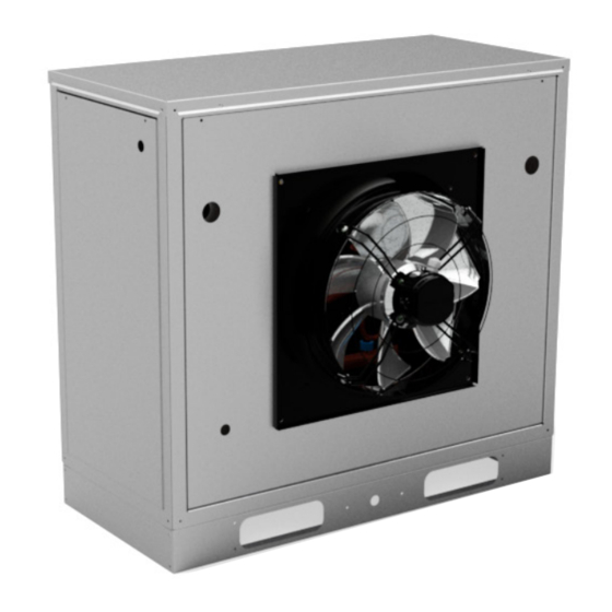
Air cooled fixed compressor chiller water generator unit
Hide thumbs
Also See for Clima-Flex CLIV Series:

Related Manuals for Daikin Clima-Flex CLIV Series


Summary of Contents for Daikin Clima-Flex CLIV Series
- Page 1 Control Manual Group: Chiller Part Number: CM CLIV Date: 10 November 2022 CLIV Series Air Cooled Fixed Compressor Chiller Water Generator Unit Model 3, 5 y 10 TR Refrigerant HFC-410A 50/60 Hz...
- Page 2 Table of Contents Safety Warning............3 General Description...........4 Features / Benefits............5 Control.................7 Manufactured in an ISO 9001 certified facility © 2022 Clima Flex . Illustration and data cover the Clima Flex product at the time of publication and we reserve the right to make changes in design and construction at any time without notice.
-
Page 3: Safety Warning
Safety Warning This manual provides information on the control data of the Clima Flex CLIV series. NOTES: Installation and maintenance must be performed only by qualified personnel who are familiar with local codes and regulations and who have experience with this type of equipment. DANGER LOCK OUT/LABEL all power sources before starting, pressurizing, depressurizing or shutting down the chiller. -
Page 4: General Description
General Description components, and various safety protections. Our units are built with design and control in mind, so we use specialized technical control software. Some of our special Our units are environmentally friendly and operate with R410A features are our own piping and wiring, fixed compressors, new refrigerant. -
Page 5: Features / Benefits
Features / Benefits EFFICIENCY of rigorous testing to ensure the efficiency, safety, durability and quality of the entire system. Our units are designed to efficiently meet the air conditioning needs All external paint is baked and meets the strictest quality standards of any project. - Page 6 Features / Benefits corrosive environments and will maintain their appearance after flow, thermal load and line voltage under the current conditions in many years of exposure. UV degradation ES2 pigments form a which the equipment operates in the field. multilayer structure throughout the paint film. Finally, the operation of the equipment is tested and verified according to AHRI’s operating standards.
-
Page 7: Control
Control MICRO WATER CHILLER UNIT Under normal conditions, the value on the display corresponds to the temperature measured by the probe B1 µC2SE is a new compact electronic controller, with the dimensions of a normal thermostat, for the complete management of chillers In Figure 1 for this version of the panel, the actual symbols are and heat pumps: it offers the possibility to manage air-to-air, air-to- indicated on the display and on the keyboard... - Page 8 Control HP1= High Pressure Alarm The unit is operating at High Pressure. As soon as the pressure is reduced the Alarm will automatically reset. LP1=Low Pressure Alarm The unit is operating at Low Pressure. As soon as the pressure rises the Alarm will automatically reset. TP= Thermal Circuit Breaker Alarm phase with voltage problems.
- Page 9 Control μCHILLER μChiller is the Carel solution for the complete management of μChiller uses the user terminal to display alarms, main variables chiller units, air/water and water/water heat pumps and motor and to configure the unit set point (User level) and manual condensing units.
- Page 10 Control DISPLAY ICONS The icons indicate the operating status of the devices and the operating mode, as shown in the following table. Icon Status Mode of operation Description System pump Active In manual operation Status of source devices (pump Active In manual operation / fan) Compressor...
- Page 11 Control • dSt1” compressor discharge temperature BLDC circuit 1; “dSt1” compressor discharge temperature BLDC circuit 2 1; • “ESC” to exit the main screen. • “EuP2” evaporating temperature circuit 2; • “SSH2” circuit 2 overheating; • “Cnd2” circuit 2 condensing temperature; •...
- Page 12 Control Alarm Description This alarm indicates when the water return sensor or water return probe is damaged or broken. This alarm indicates when the water injection sen- sor is damaged or broken. This alarm indicates when there is a census or wa- ter flow problem.
- Page 13 Control Go to the standard display Press DOWN: the command to change the cooling mode so(Clo) /at Assistance level and for A/W reversible units appears. heating (H) (ModE) - only for heat pump units. Press DOWN for 3 s: the current set point (SEtA) is displayed - read only.
- Page 14 Control INPUTS AND OUTPUTS Tabla 1. Analog inputs Physical address Electrical diagram label Name Return Sensor Injection Sensor Condenser Sensor Tabla 2. Digital inputs Physical address Electrical diagram label Name Flow sensor Heating / cooling switch High pressure switch Low pressure switch System DAC HDunit ON/OFF switch Tabla 3.
- Page 15 THIS PAGE IS INTENTIONALLY LEFT BLANK www.clima-flex.com cm-cliv-cf-eng...
- Page 16 cm-cliv-cf-eng www.clima-flex.com...