Table of Contents
Advertisement
Quick Links
Advertisement
Chapters
Table of Contents
Troubleshooting

Related Manuals for Nanni Q1100 Series


Summary of Contents for Nanni Q1100 Series
- Page 1 NANNI GENERATOR SET USER MANUAL DGBXXT090048 Q1100 Series...
-
Page 3: Q00 Tracked Changes
TRACKED CHANGES TRACKED CHANGES CODE INDEX DATE INITIALS NATURE OF TRANSLATIONS PAGES DGBXXT09048 03/2023 Creation Please note all changes and pages associated. For further clarity, please add a line in front of each change... - Page 4 TRACKED CHANGES...
-
Page 5: Table Of Contents
SUMMARY TRACKED CHANGES TRACKED CHANGES SUMMARY INTRODUCTION INTRODUCTION ABOUT THIS MANUAL Contents & updates SAFETY SAFETY SIGNALS A signal word Engine - Genset Safety Icons SAFETY PRECAUTIONS Hot Exhaust Precautions Work In Ventilated Area Waste Disposal Unwanted Engine Start Safe Maintenance Practice Work In Clean Area Protective Clothing Service Engines Safely... - Page 6 SUMMARY Water Quality for Mixing with Coolant Concentrate Testing Coolant Freeze Point LUBRICANTS Engine Oil and Filter Service Intervals — Tier 3 and Stage IIIA — OEM Applications Diesel Engine Oil — Tier 3 and Stage IIIA Oil Filters Fuel Filters Alternative and Synthetic Lubricants Lubricant Storage Mixing of Lubricants...
- Page 7 SUMMARY Routine maintenance Extraordinary maintenance Tightening torque table TROUBLE SHOOTING STORAGE STORAGE PROCEDURE Long-term storage Long-term storage procedure Batteries S11 TROUBLE SHOOTING TROUBLE SHOOTING The engine is difficult to start Low power output Sudden engine stop Exhaust smoke too black Emergency engine stop Engine overheating...
- Page 8 SUMMARY...
-
Page 9: S01 Introduction
Record the motor serial numbers and option codes (if applicable). Your Nanni agent also needs these numbers when ordering parts. File the identification numbers in a secure place. Some engine accessories, such as air filters and some instruments, are optional. -
Page 10: About This Manual
NANNI dealer will be happy to inform you of i.e., anyone renting, borrowing or buying the engine from the correct maintenance and operating procedures. -
Page 11: S02 Safety
SAFETY SAFETY SAFETY SIGNALS A signal word Engine - Genset Safety Icons SAFETY PRECAUTIONS Hot Exhaust Precautions Work In Ventilated Area Waste Disposal Unwanted Engine Start Safe Maintenance Practice Work In Clean Area Protective Clothing Service Engines Safely Proper Use Of Tools Support Engines Properly Safe Illuminated Work Area Proper Lifting Equipment... -
Page 12: Safety Signals
If you do not understand any part of this Replace missing or damaged safety signs. There can document and need assistance, contact be additional safety information contained on parts your NANNI representative. and components sourced from suppliers that is not reproduced in this Operator Manual. Read Safety Instruction Carefully read all safety messages in this manual and on your genset safety signs. -
Page 13: Engine - Genset Safety Icons
SAFETY SAFETY PRECAUTIONS ENGINE - GENSET SAFETY ICONS Some stickers are fixed directly on the engine. They are HOT EXHAUST PRECAUTIONS intended to help you to quickly identify the location of certain components and avoid possible hazards when working on the engine. Servicing machine or attachments with engine running can result in serious Ensure that these stickers are always visible and replace... -
Page 14: Safe Maintenance Practice
SAFETY SAFE MAINTENANCE PRACTICE PROPER USE OF TOOLS Understand service procedures before Use tools appropriate to the work. doing work. Keep work area clean and dry. Makeshift tools and unfollowed procedures Never lubricate, service, or adjust engine can create safety hazards. Do not use U.S while it is running. -
Page 15: Noise Protection
SAFETY NOISE PROTECTION Paint removal : • Remove paint a minimum of 100 mm (4 in.) from area to be affected by heating. If paint cannot be Prolonged exposure to loud noise can removed, wear an approved respirator mask before cause impairment or loss of hearing. -
Page 16: Safe Cooling System Service
SAFETY SAFE COOLING SYSTEM SERVICE STATIC ELECTRICITY RISK Explosive release of fluids from pressurized cooling system can cause serious burns. Shut off engine. Only remove filler cap when cool enough to touch with bare hands. Slowly loosen cap to first stop to relieve The removal of sulphur and other compounds in pressure before removing completely. -
Page 17: Handle Starting Fluid Safely (Ether)
SAFETY HANDLE STARTING FLUID SAFELY (ETHER) If acid is spilled on skin or in eyes: Starting fluid is highly flammable. Keep all sparks and flame away if using it. Keep starting fluid away from batteries and cables. • Flush skin with water To prevent accidental discharge when storing the •... -
Page 18: Live With Safety
SAFETY LIVE WITH SAFETY Before returning engine to customer, make sure engine is functioning properly, especially the safety systems. Make sure that all guards and shields are in place. PREVENT ACCIDENTS When engine is OFF, always set the trans- mission lever to neutral position. -
Page 19: S03 Fluids
FLUIDS FUELS STORING FUEL DIESEL FUEL Required Fuel Properties E-Diesel fuel LUBRICITY OF DIESEL FUEL HANDLING AND STORING DIESEL FUEL RECOMMENDED FUEL Approved fuel European standard EN15940 EN15940 (Effect on engine) BIODIESEL FUEL TESTING DIESEL FUEL MINIMIZING THE EFFECT OF COLD WEATHER ON DIESEL ENGINES Use Winter Grade Fuel Air Intake Heater Ether... -
Page 20: Fuels
10 000 mg/kg (10 000 ppm). E-Diesel fuel DO NOT use E-Diesel (Diesel fuel and ethanol blend). Use of E-Diesel fuel in any NANNI engines may void the machine warranty CAUTION ! Avoid severe injury or death due to the fire and explosion risk from using E-Diesel fuel. -
Page 21: Lubricity Of Diesel Fuel
• BEFORE using diesel fuel with sulfur content great- er than 5000 mg/kg (5000 ppm), contact your NANNI dealer. IMPORTANT! Make sure the diesel fuel used in your machine demon- Sulfur Content for Other Engines strates good lubricity characteristics. -
Page 22: Handling And Storing Diesel Fuel
Monitor water content of the fuel regularly. Paraffin-based fuel that complies with European stand- ard EN15940 can be used for all NANNI Kubota bases en- When using biodiesel fuel, the fuel filter may require more gines including EU Stage V. -
Page 23: Biodiesel Fuel
EN590 or ASTM D975 or equivalent specification. with appropriate governmental authorities prior to using biofuels. IMPORTANT! Biodiesel is not recommended by NANNI. Raw pressed vegetable oils are NOT acceptable for use as fuel in any concentration in NANNI engines. Their use could cause engine failure. -
Page 24: Minimizing The Effect Of Cold Weather On Diesel Engines
Use of fabric, cardboard, or solid winter-fronts is not rec- a lower pour point. ommended with any NANNI engine. Their use can result Cloud point is the temperature at which wax begins to in excessive engine coolant, oil, and charge air tempera- form in the fuel. -
Page 25: Diesel Engine Coolants
Warranties, including the recommended engine coolants. emissions warranty, are not conditioned on the use of NANNI coolants, parts or service Always use a recommended engine coolant, even when operating in geographical areas where freeze protection RECOMMENDED COOLANTS is not required. -
Page 26: Water Quality For Mixing With Coolant Concentrate
FLUIDS WATER QUALITY FOR MIXING WITH COOL- TESTING COOLANT FREEZE POINT ANT CONCENTRATE The use of a hand-held coolant refractometer is the quickest, easiest, and most accurate method to determine Engine coolants are a combination of three chemical coolant freeze point. This method is more accurate than components: ethylene glycol (EG) or propylene glycol (PG) a test strip or a float-type hydrometer which can produce antifreeze, inhibiting coolant additives, and quality water. -
Page 27: Lubricants
Use oil analysis to evaluate the condition of the oil and to aid in selection of the proper oil and filter service interval. Contact your NANNI dealer or other qualified service pro- vider for more information on engine oil analysis. -
Page 28: Diesel Engine Oil - Tier 3 And Stage Iiia
OIL FILTERS IIIA Filtration of oils is critically important for proper opera- tion and lubrication. NANNI brand oil filters have been de- Failure to follow applicable oil standards and drain inter- signed and produced specifically for NANNI applications. vals can result in severe engine damage that might not be covered under warranty. -
Page 29: Fuel Filters
The temperature limits and service intervals shown in this change engine fuel filters as specified in this manual. manual apply to NANNI branded fluids or fluids that have been tested and/or approved for use in NANNI equipment. Re-refined base stock products may be used if the fin-... -
Page 30: Lubricant Storage
Store containers mance. on their side to avoid water and dirt accumulation. Consult your NANNI dealer to obtain specific information Make certain that all containers are properly marked to and recommendations. identify their contents. -
Page 31: Disposing Of Waste Fluids
Inquire on the proper way to recycle or dis- pose of waste from your local environmen- tal or recycling center, or from your Nanni engine representative or service dealer. - Page 32 FLUIDS...
-
Page 33: S04 Warranty
Depending of type of engine, identification plate are as follows : 1 : Type of engine 2 : Engine serial number 3 : Engine code 4 : Nanni engine serial number Or : Indicates commercial designation of the engine. -
Page 34: Engine Homologation
The engine type can be exhaust emission certified. It Nanni designs its engines to have minimum environmen- means that Nanni guarantees that all engines of the same tal impact. This objective, however, can only type that are manufactured are approved and certified be achieved with your full cooperation. -
Page 35: Warranty
Nanni representative. NOTE! Late or improper maintenance or use of spare parts other than NANNI original spare parts will invalidate NANNI’s responsibility for the engine accordance with homologa- tion and will void the Warranty. Modifications to the engine’s settings, as well as any oth-... -
Page 36: Epa Warranty
Emissions Label. vessel. When installed in accordance with the manufacturer’s instructions, Nanni Industries Marine Diesel Propulsion NOTE! Engines without integral exhaust certified under Direc- tive 97/68/EC as amended by Directive 2004/26/EC pro-... -
Page 37: S05 Components
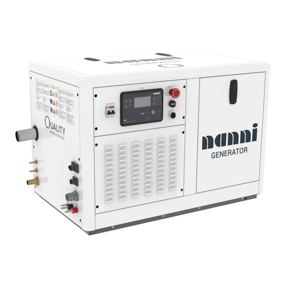
COMPONENTS COMPONENTS GENSET MAIN COMPONENTS List of components View N°1 of the generator set View N°2 of the generator set View N°3 of the generator set... - Page 38 COMPOSANTS...
-
Page 39: Genset Main Components
COMPOSANTS GENSET MAIN COMPONENTS LIST OF COMPONENTS NOTE! Minor details may differ from those shown. Some components may not be included in the order. Illustrations are not contractual. Items COMPONENTS Engine alternator Alternator belt Starter motor Control panel connector Air filter Fuel filter Coolant drain valve Fuel injection pump... -
Page 40: View N°1 Of The Generator Set
COMPOSANTS VIEW N°1 OF THE GENERATOR SET... -
Page 41: View N°2 Of The Generator Set
COMPOSANTS VIEW N°2 OF THE GENERATOR SET... -
Page 42: View N°3 Of The Generator Set
COMPOSANTS VIEW N°3 OF THE GENERATOR SET NOTE! • Always lift the generating set in using the lifting eyelets. Adjust the lifting slings to lift the unit horizontally. • For safety and operational reasons, never insert any objects or block the vents of the generator. •... -
Page 43: S06 Starting & Running
STARTING & RUNNING STARTING & RUNNING COMMAND PANEL Si-2 Description of the generator set control panel DISPLAY SCREENS & PAGES STRUCTURES STARTING & USE Starting and stop buttons BEFORE STARTING Fuel system Raw water Electric system PRELIMINARY CHECKS STARTING THE GENSET Cold climate start-up Starting with back-up batteries RUNNING... -
Page 44: Command Panel
STARTING & RUNNING COMMAND PANEL SI-2 FAULT RESET button. Use this button to ac- knowledge alarms and deactivate the horn output. Inactive alarms will disappear im- This panel integrates all the information necessary for the mediately and status of active alarms will be operation and monitoring of the generator set. -
Page 45: Display Screens & Pages Structures
STARTING & RUNNING DISPLAY SCREENS & PAGES MAIN SCREEN STRUCTURES The displayed information is structured into “pages” and “screens”. Use PAGE button to switch over the pages. MAIN SCREEN • The page Measurement consists of screens which display measured values like voltages, current, oil pressure etc., computed values like i.e. -
Page 46: Before Starting
STARTING & RUNNING BEFORE STARTING RAW WATER The raw water system cools the engine coolant and the FUEL SYSTEM exhaust gases. Fuel is drawn from the tank by the fuel feed pump and The raw water is drawn into the heat exchanger by the injected into the combustion chamber by the injection engine’s raw water pump. -
Page 47: Electric System
STARTING & RUNNING PRELIMINARY CHECKS ELECTRIC SYSTEM The electrical harness of the generating set must be kept DANGER! away from any splash of water and must be correctly fixed as high as possible in the hold. All covers must be put back in place beore starting the genset. -
Page 48: Starting The Genset
Turn on the engine coolant heater for at least 2 hours be- fore starting the engine. Additional information on cold weather operation is available from your Nanni engine distributor or authorized dealer. Synthetic oils improve flow at low temperatures, espe- Beware of polarities ! cially in Arctic conditions. -
Page 49: Running
If it is not possible to stop the generator during navigation or to repair it, try to reduce the load delivered by the gen- erator and check the whole system once back in port. If necessary, consult your local Nanni representative. 3. 3. Inspect the generator set for leaks. -
Page 50: Cold Climate Precautions
STARTING & RUNNING CAUTION! Do not forget to open the sea cock before restarting the group. COLD CLIMATE PRECAUTIONS See maintenance chapter fore more details. CAUTION! Keep the battery fully charged. An improperly charged battery may burst due to freezing. -
Page 51: Maintenance
S 07 MAINTENANCE S 07 MAINTENANCE GENERATOR SET MAINTENANCE AbOuT ThIS MANuAl GENERAlITIES MAINTENANCE INTERvAlS ChECkING ThE ENGINE OIl lEvEl Engine oil level ChECkING ThE ENGINE COOlANT lEvEl ENGINE OIl REplACEMENT Oil filling OIl fIlTER REplACEMENT ChECk fuEl hOSES ANd ClAMpS ChECk ANd ClEAN ThE AIR fIlTER hOuSING AlTERNATOR bElT Belt tensioning... - Page 52 S 07 MAINTENANCE Battery voltage Battery specific gravity...
- Page 53 S 07 MAINTENANCE...
-
Page 54: Generator Set Maintenance
CAUTION! During the warranty period, it is essential to have all work per- formed by an authorized Nanni workshop. In addition, all inter- Clean the engine before servicing. Watch for oil or fluid ventions must be recorded in the Nanni after-sales system. -
Page 55: Maintenance Intervals
) Operations must be performed in accordance with the operation and maintenance manuals for your engine. For all technical information specific to your engine, refer to the operation and maintenance manual. ) Operation to be performed in accordance with the manufacturer’s operation and maintenance manual. ) Only Q3300 & Q3800 are concerned ) Only Q3800 is concerned ) Q1100 series are out of scope REPLACE CHECK/ADJUST/CLEAN/MAINTAIN/REPLACE AS NEEDED... -
Page 56: Checking The Engine Oil Level
S 07 MAINTENANCE CHECKING THE ENGINE OIL LEVEL CHECKING THE ENGINE COOLANT LEVEL • Remove the expansion tank cap (1) and check that DANGER! the coolant level is between the low and high marks. Stop the engine before checking the oil level. Engine oil level •... -
Page 57: Engine Oil Replacement
S 07 MAINTENANCE ENGINE OIL REPLACEMENT DANGER! When changing or inspecting, be sure to level and stop the engine. ENVIRONMENT! Use a suitable container. Used oil must be disposed of in accordance with national and international laws and reg- ulations. IMPORTANT ! When using a different brand or viscosity of oil, remove •... -
Page 58: Oil Filter Replacement
Then fill up the engine oil to the specified level.. IMPORTANT! To prevent serious damage to the engine, replacement el- ement must be highly efficient. Use only a NANNI genuine filter or its equivalent. -
Page 59: Check And Clean The Air Filter Housing
S 07 MAINTENANCE CHECK AND CLEAN THE AIR FILTER HOUS- ALTERNATOR BELT Belt tensioning • Remove the air filter housing from the engine DANGER! • Wash it with soap and water Stop the engine before working on the alternator belt •... -
Page 60: Belt Replacement
S 07 MAINTENANCE FUEL FILTER CARTRIDGE REPLACEMENT DANGER! Stop the engine before replacing the fuel filter cartridge. Isolate the fuel system before replacing the filter. IMPORTANT! Water and dust from the tank and circuit are collected in this cartridge. It should therefore be replaced at the first service visit and every 250 hours of operation or annually, whichever comes first. -
Page 61: Flexible Engine Mounts
S 07 MAINTENANCE FLEXIBLE ENGINE MOUNTS the fuel filter a few turns. Open the fuel drain valve (2). On new or outdated generators, make sure that the front and rear flexible supports are properly adjusted. Check that the four flexible brackets are correctly posi- tioned, then attach them to the frame. -
Page 62: Exhaust Elbow Inspections
S 07 MAINTENANCE EXHAUST ELBOW INSPECTIONS Stainless steel dry exhaust elbow (optional for the non-soundproof version): Aluminum wet exhaust elbow : Disassembly Disassembly • Unscrew and remove the 4 bolts (1). • Unscrew and remove the 4 bolts (1). • Remove the exhaust elbow (2) with its gasket (3). -
Page 63: Tightening Of Screws, Clamps And Raw Water And Coolant Hoses
S 07 MAINTENANCE TIGHTENING OF SCREWS, CLAMPS AND RAW WATER PUMP IMPELLER REPLACEMENT RAW WATER AND COOLANT HOSES CAUTION! IMPORTANT! Before replacing the seawater pump impeller, make sure that the seawater valves are all closed and that the motor Check that the hoses are properly attached at the first is stopped. -
Page 64: Coolant Replacement
S 07 MAINTENANCE COOLANT REPLACEMENT • Install the new impeller with a rotary motion in the direction it will rotate. DANGER! Do not remove the pressure cap from the heat exchanger when the engine is hot. Then loosen the cap slightly to release excess pressure before removing it completely. -
Page 65: Coolant Filling
S 07 MAINTENANCE ANTI-GEL There are two types of antifreeze: use the permanent type (PT) for this motor. Before adding antifreeze for the first time, clean the inside of the heat exchanger by pouring fresh, cool water and draining it several times. The procedure for mixing water and antifreeze differs de- pending on the brand of antifreeze and the ambient tem- 5. -
Page 66: Hose And Clamp Replacement
S 07 MAINTENANCE HOSE AND CLAMP REPLACEMENT NOTE! The images shown may differ from your model. Coolant and raw water system DANGER! Do not remove the expansion bowl cap when the engine is hot. Then loosen the cap slightly to the stop to relieve any excess pressure before removing it completely. -
Page 67: Fuel System
S 07 MAINTENANCE THERMOSTAT REPLACEMENT Fuel system 1. Loosen the clamps (2) and remove the fuel hoses (1). DANGER! Stop the engine before replacing the thermostat. Do not remove the thermostat from the heat exchanger until the coolant temperature is too high. The thermostat should be replaced every 2 years or 500 hours, whichever comes first. -
Page 68: Thermostat Valve Opening Temperature
S 07 MAINTENANCE REPLACEMENT OF THE PRESSURIZED FILL- 4. Bleed the system and start the engine to check for leaks. ER CAP Thermostat valve opening temperature 1. Remove the pressurized cap from the expansion tank. 1. Push the thermostatic valve down and insert a string between the valve and the valve seat.. -
Page 69: Heat Exchanger Maintenance
S 07 MAINTENANCE HEAT EXCHANGER MAINTENANCE 2. Remove any internal deposits on the raw water side with a round brush. DANGER! 3. Replace cooler core if damaged. Do not remove the heat exchanger cap (1) when the en- CAUTION! gine is hot. Then loosen the cap slightly to release excess pressure before removing it completely. -
Page 70: Raw Water Pump Replacement
S 07 MAINTENANCE RAW WATER PUMP REPLACEMENT WARNING! Do not start the engine without coolant. Use a mixture DANGER! of 50% clean, fresh, non-calcareous water and 50% anti- freeze to top up the cooler. For the water-antifreeze mix- Never work on the seawater circuit without taking care to isolate the suction and discharge valves. -
Page 71: Overview Of The Raw Water Pump
S 07 MAINTENANCE Overview of the raw water pump Raw water pump installation 1. Check the condition of the spacer contact surface be- fore mounting the seal and the pump. Gasket Raw water pump Spacer Fittings Screw Washers Gasket 2. Replace the gasket (2) and after greasing it on both sides, install the raw water pump (3) using 4 screws (1) with their washers. -
Page 72: Batteries
S 07 MAINTENANCE BATTERIES Battery specific gravity • Check the specific gravity of the electrolyte in CAUTION! each cell with a hydrometer. To avoid accidental shorting, be sure to attach the pos- • When the temperature of the electrolyte differs itive cable to the positive terminal before attaching the from that to which the hydrometer has been cali- negative cable to the negative terminal. - Page 73 S 07 MAINTENANCE electrolyte level. Specific gravity varies slightly with temperature. To be exact, specific gravity decreases by 0.0007 with a 1°C in- crease (0.0004 with a 1°F increase) in temperature, and increases by 0.0007 with a 1°C decrease (0.0004 with a 1°F decrease).
- Page 74 S 07 MAINTENANCE...
-
Page 75: S08 Al Ternator
AL TERNATOR AL TERNATOR ALTERNATOR (8CM50 - 10CT50 - 9CM60 & 11CT60) Marking data Alternator nameplate Machine description DSR digital controller General description and operating principle Safety requirement Alternator safety devices Safety labels Personal protective equipment Residual risks Conventional symbols and symbol descriptions Operating temperature Electrical connection Rotation and sequence of phases... - Page 76 AL TERNATOR...
-
Page 77: Alternator (8Cm50 - 10Ct50 - 9Cm60 & 11Ct60)
AL TERNATOR ALTERNATOR (8CM50 - 10CT50 - 9CM60 & 11CT60) MARKING DATA Alternator nameplate N° Identification N° Identification Serial number Class of nominal characteristics Model Connection type Update index Excitation voltage Number of phases Excitation current Type of service Power versus temperature (20) Date of manufacture mm/yyyy Ambient temperature Rated speed of rotation... -
Page 78: Machine Description
AL TERNATOR MACHINE DESCRIPTION GENERAL DESCRIPTION AND OPERATING PRINCIPLE The NPE series alternators are self-regulating, without rings or brushes, with 2 and 4 poles. They have rotating The drive motor is connected to the flange and the discs inductors with a damping cage and inclined notched (1) of the alternator. -
Page 79: Safety Requirement
AL TERNATOR SAFETY REQUIREMENT Before any cleaning, lubrication or maintenance work is carried out, the engine to which the alternator is coupled must not be running but must be disconnected from its power sources. To switch off an alternator, it is necessary to follow The alternator is not fitted with an emergency stop, but it will stop instantly according to the shutdown system provided by the installer. -
Page 80: Residual Risks
In case of exceptional operations and upon written request for maintenance operations, please contact your authorized NANNI dealer. Before installing the generator, arrangements must be made to ground the machine. For this reason, you must ensure that the grounding... -
Page 81: Operating Temperature
AL TERNATOR regulations of the country where the generator will be WARNING! installed. After long periods of storage or in the presence of CAUTION! moisture/condensation, check the insulation condition. The test must be performed by a qualified technician. The final installer is responsible for the installation of all Before performing such a test, it is necessary to protections (disconnecting devices, protection against disconnect the voltage regulator. -
Page 82: Electrical Connection
AL TERNATOR ELECTRICAL CONNECTION Once the connection has been made, check the tightening torques of the terminals, which must comply with the instructions given in the chapter “General tightening The operation must be performed by an electrical torques”. service technician. Once the connection is complete, refit the terminal box cover. -
Page 83: Starting And Stopping Operations
All the instrumentation for starting, running and stopping Before approaching or touching the alternator, make sure the system is provided by NANNI. it is de-energized and at room temperature; at this point, it can be cleaned externally using compressed air. -
Page 84: Maintenance
AL TERNATOR MAINTENANCE ROUTINE MAINTENANCE The NPE series alternators are designed to provide a long Evaluation of the condition of the windings after long maintenance-free life. periods of storage or inactivity. Intervention type Operator CAUTION! Before performing this operation, read the safety requirements at the beginning of this section. -
Page 85: Assessment Of Current Operation (Absence Of Abnormal Noise Or Vibration)
AL TERNATOR Assessment of current operation (absence of abnormal noise or vibration). Intervention type Operator PPE to wear Periodicity fig b Every 2500 hours of use Materials and equipment Outils d’atelier At regular intervals, we recommend checking that the alternator is running smoothly without any abnormal noise or vibration. -
Page 86: Extraordinary Maintenance
EXTRAORDINARY MAINTENANCE Mechanical check of the fastening bolts and, in particular, of the electrical connections. DANGER! Intervention type Operator This type of maintenance must be performed by a NANNI dealer. PPE to wear Periodicity CAUTION! Perform extraordinary maintenance accurately and as Every 2500 hours of use often as specified by the manufacturer. -
Page 87: Tightening Torque Table
• Replace the regulator • Check the uniformity of the rotation. Unstable voltage • Adjust the stability of the reg- ulator by acting on the “STAB. For any other defects, please contact a NANNI dealer. -
Page 89: S10 Storage
STORAGE S10 STORAGE STORAGE PROCEDURE Long-term storage Long-term storage procedure Batteries... -
Page 90: Storage Procedure
5. Stop the engine and remove the boat from the water. It may be necessary to adapt these operations depending 6. Drain and clean raw water system components. on the weather conditions. Contact an authorized Nanni workshop for more information. 7. Protect the components from corrosion. -
Page 91: Tightening Torque Table
STORAGE 11. Check the condition of the belts. Adjust belt tension. CAUTION! 12. Drain the fuel tank. Packaged or not, the alternator must be stored in a cool, dry place, protected from vibrations and never exposed 13. Open the fuel system valves. Bleed the system to the elements. -
Page 92: Batteries
STORAGE BATTERIES When storing the unit, adjust the electrolyte level of the battery and store it in a dry place at room temperature. Recharge the battery as often as possible to extend its life. WARNING! Do not leave the battery unattended for a long time: it will be deeply discharged (about 7 to 8 volts). -
Page 93: S11 Trouble Shooting
If the engine does not work properly, use the following ta- too low. • Attempt to break in the valves. ble to identify the cause. If the cause cannot be found, contact an authorised Nanni workshop. • Fill up with fuel. Lack of fuel. •... -
Page 94: Sudden Engine Stop
Replace the oil filter every second due to a lack of • Injection pump stalling. oil change. oil. • Injection failure • Check bearing clearance. Combustion • Valve clearance incomplete. • Compression ratio, etc. Checks to be carried out by NANNI Dealer... -
Page 95: Emergency Engine Stop
TROUBLE SHOOTING EMERGENCY ENGINE STOP ENGINE OVERHEATING Defect Solutions Defect Solutions Engine speed • Check timing and injection. Oil level too low. • Check the oil circuit, add oil. variations. Unusual noise. • Check all rotating parts. Extended • Replace the belt or adjust the or broken tension. - Page 96 TROUBLE SHOOTING...