
Related Manuals for NANOTEC SMCI47-S


Summary of Contents for NANOTEC SMCI47-S
- Page 1 Technical Manual Stepper motor control SMCI47-S NANOTEC ELECTRONIC GmbH & Co. KG Tel. +49 (0)89-900 686-0 Kapellenstraße 6 +49 (0)89-900 686-50 D-85622 Feldkirchen b. Munich, Germany info@nanotec.com...
- Page 2 Technical Manual SMCI47-S V2.0 Editorial Editorial © 2011 ® Nanotec Electronic GmbH & Co. KG Kapellenstraße 6 D-85622 Feldkirchen b. Munich, Germany Tel.: +49 (0)89-900 686-0 Fax: +49 (0)89-900 686-50 Internet: www.nanotec.com All rights reserved! MS-Windows 2000/XP/Vista are registered trademarks of Microsoft Corporation.
- Page 3 For criticisms, proposals and suggestions for improvement, please contact the above address or send an email to: info@nanotec.com Additional manuals Please also note the following manuals from Nanotec: NanoPro Configuration of controllers with the User Manual...
-
Page 4: Table Of Contents
Stepper motor connection: Connector X4................15 Voltage supply connection: Connector X5 ................16 RS485 network/CANopen: Connector X6................17 Operating modes........................ 22 Serial operating modes (SMCI47-S-2)................. 22 CANopen operating modes (SMCI47-S-3) ................24 Troubleshooting......................... 25 Technical data ........................27 Index ..............................29 Issue: V 2.2... -
Page 5: Overview
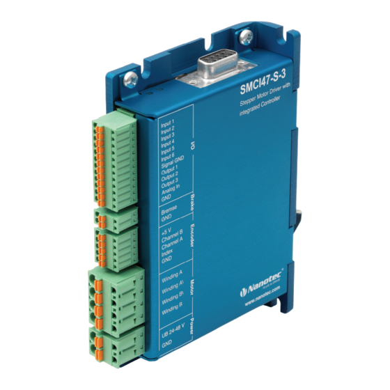
Overview Overview Introduction The stepper motor control SMCI47-S is an extremely compact and cost-effective constant current power output stage with integrated Closed-Loop current control. Due to the great capacity and functions available, it offers designers and developers a rapid and simple method of resolving numerous drive requirements with less programming effort. -
Page 6: Connection And Commissioning
Connection and commissioning Connection diagram Introduction In order to operate a stepper motor using the stepper motor control SMCI47-S, you must carry out the wiring in accordance with the connection diagram below. Connectors X1 and X3 can be optionally used. - Page 7 Technical Manual SMCI47-S V2.0 Connection and commissioning Issue: V 2.2...
-
Page 8: Commissioning
This section describes the main first steps you need to take to be able to begin working with the SMCI47-S and the NanoPro software (RS485) or NanoCAN software (CANopen) from a PC. You will find more detailed information in the separate NanoPro and NanoCAN manuals. - Page 9 Select the <Communication> tab. In the "Port" field, select the COM port to which The number of the COM the SMCI47-S is connected. port to which the controller is connected can be found in the device manager of your Windows PC (System Control/System/Hardware).
- Page 10 Technical Manual SMCI47-S V2.0 Connection and commissioning Commissioning with NanoCAN (SMCI47-S-3) Proceed as follows to commission the SMCI47-S-3 controller. More detailed information can be found in the separate NanoCAN manual. Step Action Note Install the NanoCAN control software on your Download of www.nanotec.com...
-
Page 11: Connections And Circuits
Technical Manual SMCI47-S V2.0 Connections and circuits Connections and circuits Inputs and outputs (I/O): Connector X1 Introduction An overview of the assignments can be found in the wiring diagram in Section 2.1. This section looks in detail at the assignment, functions and circuits of connector X1. - Page 12 NanoPro. Input circuits All inputs (apart from the "Analogue In" input) are electrically isolated by optocouplers from the voltage supply of the SMCI47-S and designed for 5-24 V input signals at an input current of 10 mA. Note: The voltage must not exceed 24 V. It should drop below 2 V for safe switching off and be at least 4.5 V for safe switching on.
-
Page 13: Brake Connection: Connector X2
Technical Manual SMCI47-S V2.0 Connections and circuits Brake connection: Connector X2 Function The connector X2 is used to connect an external safety brake for the motor. This allows the holding torque and therefore the system stiffness to be increased further when necessary. -
Page 14: Encoder Connection: Connector X3
The following encoder resolutions can normally be processed by the controller: 192, 200, 256, 400, 500, 512, 1000, 1024, 2000, 2048. Recommended: Where possible, use Nanotec encoders with the order number WEDS/WEDL-5541 Xxx. If an encoder is not used, the "Disable" mode must be set in the <Error correction>... -
Page 15: Stepper Motor Connection: Connector X4
Connections and circuits Stepper motor connection: Connector X4 General information The motor is connected to the SMCI47-S with a 4-wire cable. Twisted wire pair cables with braided shields are recommended. Danger of electrical surges Mixing up the connections can destroy the output stage! See the data sheet of the connected stepper motor. -
Page 16: Voltage Supply Connection: Connector X5
Voltage supply connection: Connector X5 Permissible operating voltage The permissible operating voltage for the SMCI47-S stepper motor control lies between +24 and +48 V DC; it must not exceed 50 V or fall below 21 V. A charging condenser with minimum 4700 µF (10000 µF) must be provided for the operating voltage to prevent exceeding the permissible operating voltage (e.g. -
Page 17: Rs485 Network/Canopen: Connector X6
CANopen (SMCI47-S-3) With the SMCI47-S, it is also possible to control the motor via CANopen. If you use the control with CANopen you can use the additional safety function of the separate logic supply: Even when the voltage supply of the SMCI47-S is interrupted,... - Page 18 Technical Manual SMCI47-S V2.0 Connections and circuits CANopen connection A suitable CAN interface adapter (e.g. USB adapter from IXXAT or PEAK) is required for connecting with a PC. CANopen standard connector assignment (on the adapter) Pin no. Name CAN low...
- Page 19 Technical Manual SMCI47-S V2.0 Connections and circuits Circuit diagram RS485 network Issue: V 2.2...
- Page 20 An intelligent converter, which automatically switches to transmission mode when a start bit is received at the RS232 interface and returns to reception mode at the end of the stop bit, enables two-wire operation of the SMCI47-S. This solution requires no software support.
- Page 21 Technical Manual SMCI47-S V2.0 Connections and circuits Setting the CANopen module address There are two basic ways of setting the CANopen node ID and the baud rate: • Hardware setting: Via rotary switches on the control • Software setting: With NanoCAN, see separate manual for NanoCAN.
-
Page 22: Operating Modes
Technical Manual SMCI47-S V2.0 Operating modes Operating modes Serial operating modes (SMCI47-S-2) Introduction Depending on the travel profile, the motor can be operated using different operating modes. Due to the great capacity and functions available, it offers designers and developers a rapid and simple method of resolving numerous drive requirements with less programming effort. - Page 23 Technical Manual SMCI47-S V2.0 Operating modes Operation mode Application Clock direction mode, left Use this mode when you wish to operate the motor with a superordinate controller (e.g. CNC controller). Clock direction mode, right In the clock direction mode, the motor is operated via...
-
Page 24: Canopen Operating Modes (Smci47-S-3)
Technical Manual SMCI47-S V2.0 Operating modes CANopen operating modes (SMCI47-S-3) Introduction The motor can be operated using a total of 5 different operating modes in CANopen mode. More detailed information can be found in the separate NanoCAN manual. Overview of operating modes and their areas of application... -
Page 25: Troubleshooting
Danger of electrical surges An operating voltage > 50 V and incorrect connections can destroy the end stage. Never disconnect the motor when operating voltage is applied! Never disconnect lines when live! Possible errors in RS485 mode (SMCI47-S-2) Error Possible cause Rectification... - Page 26 Technical Manual SMCI47-S V2.0 Troubleshooting Possible errors in CANopen mode (SMCI47-S-3) Error Possible cause Rectification The wrong node ID has been On the <Configuration & NMT> tab communication set. in NanoCAN, select the node ID that with the is set on the rotary switches of the controller controller.
-
Page 27: Technical Data
SMCI47-S-2: RS485 (4-wire) • 115200 bps (adjustable) • 1 start bit, 8 data bits, 1 stop bit • No parity SMCI47-S-3: CAN bus (CANopen) • Extended functionality • Brake output • Separate circuit for supply and processor • Closed-Loop capable... - Page 28 Approx. 67 °C Max. ambient temperature 0 to 40 °C SMCI47-S dimensions A complete set of datasheets is available for downloading at www.nanotec.com. Connectors The following connectors are available on the SMCI47-S: • Connectors X1, X3: Phoenix connector, Type MICRO COMBICON •...
-
Page 29: Index
Technical Manual SMCI47-S V2.0 Index Index Accessories for voltage supply......16 NanoJ.............. 6 Brake .............13 Operating mode CANopen........... 24 Operating modes CANopen ..........6, 10, 17 serial............22 Closed-Loop current control ......5 Operating voltage.......... 16 Commissioning ..........8 Output circuits ..........12 Connection diagram inputs and outputs (I/O)11 Connection diagram stepper motor ....15...