
Related Manuals for NANOTEC SMCI12


Summary of Contents for NANOTEC SMCI12
- Page 1 Technical Manual Stepper controller SMCI12 NANOTEC ELECTRONIC GmbH & Co. KG Tel. +49 (0)89-900 686-0 Gewerbestraße 11 +49 (0)89-900 686-50 D-85652 Landsham near Munich, Germany info@nanotec.de...
- Page 2 Technisches Handbuch SMCI12 Editorial Editorial © 2010 ® Nanotec Electronic GmbH & Co. KG Gewerbestraße 11 D-85652 Landsham / Pliening, Germany Tel.: +49 (0)89-900 686-0 Fax: +49 (0)89-900 686-50 Internet: www.nanotec.de All rights reserved! MS-Windows 2000/XP/Vista are registered trademarks of Microsoft Corporation.
- Page 3 Target group This technical manual is aimed at designers and developers who need to operate a Nanotec stepper motor without much experience in stepper motor technology. Important information This technical manual must be carefully read before installation and commissioning of the stepper motor control.
-
Page 4: Table Of Contents
Technisches Handbuch SMCI12 Contents Contents Overview ..........................5 Connection and commissioning ..................7 Overview ..........................7 Connection diagram ....................... 8 Commissioning........................9 Connections and circuits ....................12 Inputs and outputs: connector X11 ..................12 Stepper motor connection: Connector X10................14 Power supply and RS485/CANopen interface: Connector X12........... -
Page 5: Overview
The stepper motor control is available in the following variants: • SMCI12: For control via RS485 • SMCI12-3: For control via CANopen Unless otherwise specified, the term "SMCI12" is used for both variants in this manual. SMCI12 functions The stepper motor control SMCI12 contains the following functions: •... - Page 6 Technisches Handbuch SMCI12 Overview Settings The operating behavior of the motor can be set and optimized according to individual requirements by setting the motor-related parameters. The parameters can be set using the NanoPro software and significantly reduce commissioning time. More detailed information on this can be found in the separate NanoPro user manual.
-
Page 7: Connection And Commissioning
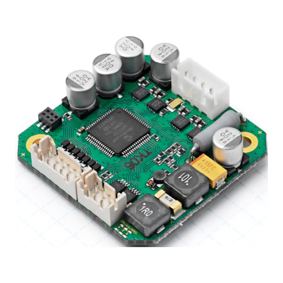
Technisches Handbuch SMCI12 Connection and commissioning Connection and commissioning Overview Plug connections The controller has the following connectors: X10 (JST-XH): stepper motor connection X11 (JST-PHD): inputs and outputs X12 (JST-PHD): power supply and interface RS485 or CANopen Configuration The following figure shows the configuration of the connectors on the printed circuit board. -
Page 8: Connection Diagram
Technisches Handbuch SMCI12 Connection and commissioning Connection diagram To operate a stepper motor with the SMCI12 stepper motor control, the wiring must be implemented according to the following connection diagram. Issue: V 1.0... -
Page 9: Commissioning
This section describes the main first steps you need to take to be able to quickly begin working with the SMCI12 if you are using the NanoPro (SMCI12) or NanoCAN (SMCI12-3) software from a PC. You will find more detailed information in the separate NanoPro and NanoCAN manuals. - Page 10 Action Note In the "Port" field, select the COM port to which The number of the COM the SMCI12 is connected. port to which the controller is connected can be found in the device manager of your Windows PC (System Control/System/Hardware).
- Page 11 Technisches Handbuch SMCI12 Connection and commissioning Commissioning with NanoCAN (SMCI12-3 with CANopen firmware) Proceed as follows to commission the controller with the CANopen firmware. More detailed information can be found in the separate NanoCAN manual. Step Action Note Install the NanoCAN control software on your Download of www.nanotec.com...
-
Page 12: Connections And Circuits
Technisches Handbuch SMCI12 Connections and circuits Connections and circuits Inputs and outputs: connector X11 Introduction An overview of the assignments can be found in the connection diagram in Section 2.1. This section looks in detail at the assignment, functions and circuits of the connector X11. - Page 13 Signal states at the outputs (SMCI12 with RS485 firmware) Note: In the SMCI12-3 with CANopen firmware, the status of the controller is not displayed at the outputs. The following table shows the possible signal states at the outputs 1 to 3:...
-
Page 14: Stepper Motor Connection: Connector X10
Connections and circuits Stepper motor connection: Connector X10 General information The motor is connected to the SMCI12 with a 4-wire cable. Twisted wire pair cables with braided shields are recommended. Danger of electrical surges Mixing up the connections can destroy the output stage! See the data sheet of the connected stepper motor. -
Page 15: Power Supply And Rs485/Canopen Interface: Connector X12
Power supply connection Permissible operating voltage The permissible operating voltage of the stepper motor control SMCI12 lies within the range 12-24 V DC and must not exceed 26 V or undershoot 11 V. A charging condenser with minimum 4700 µF (10000 µF) must be provided for the operating voltage to prevent exceeding the permissible operating voltage (e.g. -
Page 16: Rs485 Network/Canopen Interface
3.3.3 RS485 network/CANopen interface SMCI12 in a network Up to 254 (SMCI12) or 127 (SMCI12-3) stepper motor controls can be controlled in a network from a PC or PLC. These network connections are set up via the RS485/CANopen interface. Two-wire operation RS485 To enable RS485 two-wire transmission capability, all bus stations must have a direction control. - Page 17 Technisches Handbuch SMCI12 Connections and circuits Circuit diagram RS485 network Issue: V 1.0...
-
Page 18: Operating Modes
Technisches Handbuch SMCI12 Operating modes Operating modes Serial operating modes Introduction Depending on the travel profile, the motor can be operated in serial mode using different operating modes. Due to the great capacity and functions available, it offers designers and developers a rapid and simple method of resolving numerous drive requirements with less programming effort. - Page 19 Technisches Handbuch SMCI12 Operating modes Operation mode Application Clock direction mode, Use this mode when you wish to operate the motor left/right with a superordinate controller (e.g. CNC controller). In the clock direction mode, the motor is operated via Clock direction mode two inputs with a clock and a direction signal from a Ext.
-
Page 20: Canopen Operating Modes
Technisches Handbuch SMCI12 Operating modes CANopen operating modes Introduction The motor can be operated using a total of 4 different operating modes in CANopen mode. More detailed information can be found in the separate NanoCAN manual. Overview of operating modes and their areas of application... -
Page 21: Troubleshooting
Click on the <Yes> button to stop the the controller during the output travel profile. of a travel profile. The SMCI12 switches back to the "Ready" state. The data can then be resent to the controller. Transmission Data transmission to the... - Page 22 Technisches Handbuch SMCI12 Troubleshooting Possible errors in CANopen mode Error Possible cause Rectification The wrong node ID has been On the <Configuration & NMT> tab communication set. in NanoCAN, select the node ID that with the is set on the rotary switches of the controller controller.
-
Page 23: Technical Data
Technisches Handbuch SMCI12 Technical data Technical data Electrical connections Operating voltage V DC 12-24 V ±4% Max. phase current Adjustable up to max. 2.7 A/phase Continuous current 1.8 A/phase Current drop Adjustable 0 to 150% of rated current Interface • RS-485 (4-wire), 115200 bps (adjustable) - Page 24 Technisches Handbuch SMCI12 Technical data SMCI12 dimensions A complete set of datasheets is available for downloading at www.nanotec.de. Issue: V 1.0...
-
Page 25: Index
Technisches Handbuch SMCI12 Index Index Accessories for voltage supply......16 Operating modes CANopen........... 20 serial............18 CANopen ...........11, 15, 16 Operating voltage.......... 15 Commissioning ..........9 Output circuits ..........13 Connector X10..........14 Connector X11..........12 Connector X12..........15 Pin assignment connector X10 ........... 14 connector X11 ...........