Table of Contents

Related Manuals for Gigabyte R133-C11-AAB1


Summary of Contents for Gigabyte R133-C11-AAB1
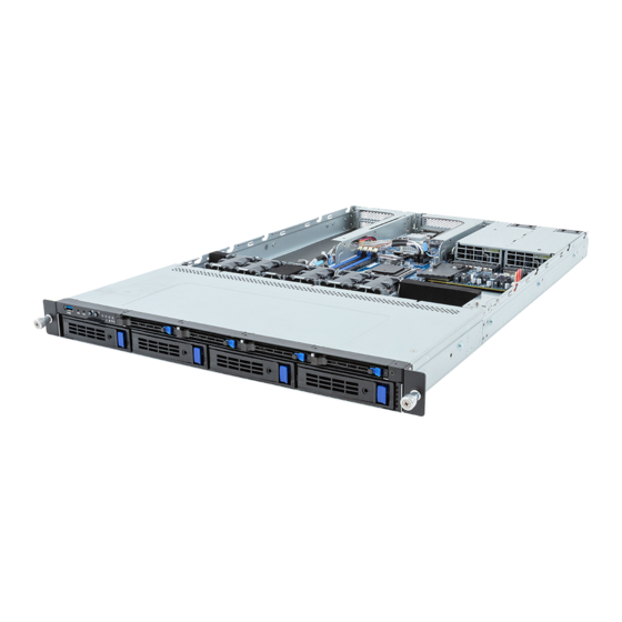
- Page 1 R133-C11-AAB1 R133-C11-AAG1 AMD Ryzen™ 7000 Server System - 1U UP 8-Bay SATA Dual 550W (240V) 80 PLUS Platinum redundant power supply (AAB1) Dual 800W (240V) 80 PLUS Titanium redundant power supply (AAG1) User Manual Rev. 1.0...
- Page 2 For GIGABYTE distributors and resellers, additional sales & marketing materials are available from our reseller portal: http://reseller.b2b.gigabyte.com For further technical assistance, please contact your GIGABYTE representative or visit https://esupport.gigabyte.com/ to create a new support ticket For any general sales or marketing enquiries, you may also message GIGABYTE server directly by email: server.grp@gigabyte.com...
- Page 3 Conventions The following conventions are used in this user's guide: NOTE! Pieces of additional information related to the current topic. CAUTION! Precautionary measures to avoid possible hardware or software problems. WARNING! Alerts to any damage that might result from doing or not doing specific actions.
- Page 4 Server Warnings and Cautions Before installing a server, be sure that you understand the following warnings and cautions. WARNING! To reduce the risk of electric shock or damage to the equipment: • Do not disable the power cord grounding plug. The grounding plug is an important safety feature.
- Page 5 Electrostatic Discharge (ESD) CAUTION! ESD CAN DAMAGE DRIVES, BOARDS, AND OTHER PARTS. WE RECOMMEND THAT YOU PERFORM ALL PROCEDURES AT AN ESD WORKSTATION. IF ONE IS NOT AVAILABLE, PROVIDE SOME ESD PROTECTION BY WEARING AN ANTI-STATIC WRIST STRAP AT- TACHED TO CHASSIS GROUND -- ANY UNPAINTED METAL SURFACE -- ON YOUR SERVER WHEN HANDLING PARTS.
- Page 6 Installing or removing jumpers: A jumper is a small plastic encased conductor that slips over two jumper pins. Some jumpers have a small tab on top that can be gripped with fin-gertips or with a pair of fine needle nosed pliers. If the jumpers do not have such a tab, take care when us- ing needle nosed pliers to remove or install a jumper;...
-
Page 7: Table Of Contents
Table of Contents Chapter 1 Hardware Installation ................... 11 Installation Precautions .................. 11 Product Specifications ..................12 System Block Diagram ................... 16 Chapter 2 System Appearance ..................17 Front View ...................... 17 Rear View ....................... 18 Front Panel LED and Buttons ................ 19 Rear System LAN LEDs ................. - Page 8 Chapter 5 BIOS Setup ....................48 The Main Menu ....................50 Advanced Menu ..................... 52 5-2-1 Trusted Computing ....................53 5-2-2 AMD fTPM Configuration ..................55 5-2-3 AST2600 Super IO Configuration ................56 5-2-4 S5 RTC Wake Settings ...................58 5-2-5 Serial Port Console Redirection ................59 5-2-6 CPU Configuration ....................63 5-2-7...
- Page 9 BIOS Recovery .................... 104 BIOS POST Beep code (AMI standard) ............105 5-9-1 PEI Beep Codes ....................105 5-9-2 DXE Beep Codes ....................105 - 9 -...
- Page 10 This page intentionally left blank - 10 -...
-
Page 11: Chapter 1 Hardware Installation
Chapter 1 Hardware Installation Installation Precautions The motherboard/system contain numerous delicate electronic circuits and components which can become damaged as a result of electrostatic discharge (ESD). Prior to installation, carefully read the service guide and follow these procedures: • Prior to installation, do not remove or break motherboard S/N (Serial Number) sticker or warranty sticker provided by your dealer. -
Page 12: Product Specifications
Product Specifications NOTE: We reserve the right to make any changes to the product specifications and product-related information without prior notice. System Security Server Socket Operating Properties Š 1U Dimension Š 438 (W) x 43.5 (H) x 710 (D) mm System fan Power Supply Š... - Page 13 Expansion Slot PCIe Cable: 1 x PCIe x16 (Gen5 x16) FHFL slot, from CPU, for GPUs* Š *Max 300W for GPUs Š Riser Card CRSE016: 1 x PCIe x4 (Gen4 x4) FHHL slot, from CPU Š 1 x M.2 slot: M-key Š...
- Page 14 ocket Security Server Operating Properties System fan Power Supply Power Supply Š Dual 800W (240V) 80 PLUS Platinum redundant PSU (AAB1) AC Input: Š 100-240V~/ 10-5A, 50-60Hz DC Input: Š 240Vdc/ 4A DC Output: Š Max 800W/ 100-240V~ or 240Vdc Input Š...
- Page 15 System Š Aspeed® AST2600 management controller Management Š GIGABYTE Management Console (AMI MegaRAC SP-X) web interface Š Dashboard Š HTML5 KVM Š Sensor Monitor (Voltage, RPM, Temperature, CPU Status …etc.) Š Sensor Reading History Data Š FRU Information Š SEL Log in Linear Storage / Circular Storage Policy Š...
-
Page 16: System Block Diagram
System Block Diagram 2-Channel DDR5, 4 x DIMM slots PCIe 5.0 x16 PCIe x16 Speed up to 5200MHz (2DPC) (for GPU) Riser CRSE016 PCIe 4.0 x4 PCIe x4 AMD Socket AM5 PCIe 3.0 x4 BCM57416 USB3.2 Gen1 x1 Ryzen 7000 Series 1 x USB3.2 Gen1 2 x 10GbE LAN (front) -
Page 17: Chapter 2 System Appearance
Chapter 2 System Appearance Front View HDD4 HDD5 HDD6 HDD7 HDD0 HDD1 HDD2 HDD3 Description Front USB 3.2 Gen1 Port x 2 Front Panel LEDs and Buttons 2.5" 9.5mm Drive Bays 3.5"/2.5" Drive Bays • Refer to section 2-3 Front Panel LEDs and Buttons for a detailed description of the function of the LEDs. -
Page 18: Rear View
Rear View SLOT3 SLOT2 PSU2 PSU1 SLOT1 Description ID Button with LED 10 GbE LAN Port x 2 1 GbE LAN Port x 2 Server Management LAN Port USB 3.2 Gen1 Port x 2 Mini DP Port PCIe Card Slot GPU Card Slot System Appearance - 18 -... -
Page 19: Front Panel Led And Buttons
Front Panel LED and Buttons No. Name Color Status Description Press the button server generates a NMI to the processor NMI button if the multiple-bit ECC errors occur, which effectively halt the server. Reset Button Press the button to reset the system. ID Button Press the button to activate system identification Green... -
Page 20: Rear System Lan Leds
Rear System LAN LEDs Name Color Status Description Green 10 Gbps data rate 10GbE Yellow 1Gbps data rate Speed LED 100 Mbps data rate Link between system and network or no access Green 10GbE Link / Blink Data transmission or reception is occurring. Activity LED No data transmission or reception is occurring. -
Page 21: Power Supply Unit Led
Power Supply Unit LED PSU LED State Description No AC power to all power supplies 1Hz Green Blinking AC present / only standby on / Cold redundant mode 2Hz Green Blinking Power supply firmware updateing mode AC cord unplugged or AC power lost; with a second power supply in parallel still with AC input power Amber Power supply critical event causing shut down:... -
Page 22: Hard Disk Drive Leds
Hard Disk Drive LEDs 3.5" Hard Disk Drive 2.5" 9.5mm Hard Disk Drive HDD Present RAID SKU LED #1 Locate Rebuilding HDD Access Fault (No Access) Green ON(*1) BLINK (*2) Disk LED (LED on Back Panel) Amber No RAID configuration Removed HDD Green ON(*1) -
Page 23: Chapter 3 System Hardware Installation
Chapter 3 System Hardware Installation Pre-installation Instructions Computer components and electronic circuit boards can be damaged by discharges of static electricity. Working on computers that are still connected to a power supply can be extremely dangerous. Follow the simple guidelines below to avoid damage to your computer or injury to yourself. -
Page 24: Removing And Installing The Chassis Cover
Removing and Installing the Chassis Cover Before you remove or install the system cover • Make sure the system is not turned on or connected to AC power. Follow these instructions to remove the chassis cover: Remove the screws on both sides of the back chassis cover. (Note: For safe shipping, installation screws are added and should be removed before deployment/putting it in the server cabinet.) Remove the screw securing the back chassis cover. -
Page 25: Removing And Installing The Hard Disk Drive
Removing and Installing the Hard Disk Drive Read the following guidelines before you begin to install the hard disk drive: • Take note of the HDD tray orientation before sliding it out. • The tray will not fit back into the bay if it is inserted incorrectly. •... - Page 26 Follow these instructions to install a 2.5" hard disk drive into 3.5" HDD Tray: Press the release button. Extend the locking lever. Pull the locking lever in the direction indicated to remove the HDD tray. Align the hard disk drive with the positioning screw on the HDD tray. Secure the hard disk drive with five screws.
- Page 27 Follow these instructions to install a 2.5" HDD: Press the release button. 2. Extend the locking lever. 3. Pull the locking lever in the direction indicated to remove the HDD tray. 4. Align the hard disk drive with the positioning stud on the HDD tray. 5.
-
Page 28: Removing And Installing The Fan Duct
Removing and Installing the Fan Duct Follow these instructions to remove the fan duct: Lift up to remove the fan duct. To reinstall the fan duct, align the fan duct with the guiding groove. Push down the fan duct until it is firmly seated on the system. -
Page 29: Removing And Installing The Heat Sink
Removing and Installing the Heat Sink Read the following guidelines before you begin to install the heat sink: • Always turn off the computer and unplug the power cord from the power outlet before installing the heat sink to prevent hardware damage. •... -
Page 30: Removing And Installing The Cpu
Removing and Installing the CPU Read the following guidelines before you begin to install the CPU: • Make sure that the motherboard supports the CPU. • Always turn off the computer and unplug the power cord from the power outlet before installing the CPU to prevent hardware damage. - Page 31 • Lock the CPU by using a Torx T20 screwdriver to tighten screw. • When installing the heatsink to CPU, use a Torx T20 screwdriver to tighten 4 captive nuts in sequence as 1-4. • The screw tightening torque: 13.5 ± 0.5 kgf-cm. •...
-
Page 32: Removing And Installing Memory
Removing and Installing Memory Read the following guidelines before you begin to install the memory: • Make sure that the motherboard supports the memory. It is recommended that memory of the same capacity, brand, speed, and chips be used. • Always turn off the computer and unplug the power cord from the power outlet before installing the memory to prevent hardware damage. -
Page 33: Removing And Installing A Memory Module
3-6-2 Removing and Installing a Memory Module Before installing a memory module, make sure to turn off the computer and unplug the power cord from the power outlet to prevent damage to the memory module. Be sure to install DDR5 DIMMs on to this motherboard. -
Page 34: Removing And Installing The Pcie Card
Removing and Installing the PCIe Card • Voltages can be present within the server whenever an AC power source is connected. This voltage is present even when the main power switch is in the off position. Ensure that the system is powered off and all power sources have been disconnected from the server prior to installing a PCIe card. -
Page 35: Installing The Gpu Card (Optional)
Installing the GPU Card (Optional) Before you install the GPU card: • Voltages can be present within the server whenever an AC power source is connected. This voltage is present even when the main power switch is in the off position. Ensure that the system is powered down and all power sources have been disconnected from the server prior to installing a GPU card. -
Page 36: Installing The M.2 Device And Heat Sink
Installing the M.2 Device and Heat Sink CAUTION The position of the stand-off screw will depend on the size of the M.2 device. The stand-off screw is pre-installed for 22110 cards as standard. Refer to the size of the M.2 device and change the position of the stand-off screw accordingly. -
Page 37: Removing And Installing The Power Supply
3-10 Removing and Installing the Power Supply Follow these instructions to replace the power supply: Flip up and then grasp the power supply handle. Press the retaining clip on the right side of the power supply unit in the direction indicated. Pull out the power supply unit using the handle. -
Page 38: Cable Routing
3-11 Cable Routing Motherboard: FP_1 Front IO Board: FP_1 Front Panel LEDs and Buttons Cable Front IO Board: FP_1 Motherboard: FUSB_1 Front Panel USB 3 Ports Cable System Hardware Installation - 38 -... - Page 39 Motherbord: BP_1 HDD Backplane Board Signal Cable (CBP1047) F/ HDD Board: BP_1 F/ HDD Board (CBP1047): BP_Series HDD Backplane Board Signal Cable (CBP1045) F/ HDD Board (CBP1045): BP_1 System Hardware Installation - 39 -...
- Page 40 Power Board: BP_ATX1 HDD Backplane Board Power Cable (CBP1047) F/ HDD Board: BP_2X7 Power Board: BP_ATX2 HDD Backplane Board Power Cable (CBP1045) F/ HDD Board: BP_2X7 System Hardware Installation - 40 -...
- Page 41 Motherboard: SATA/SL_SATA1 F/ HDD Board (CBP1047): SATA Cable A1: SATA0 (P0) A2: SATA1 (P1) A3: SATA2 (P2) A4: SATA3 (P3) Motherboard: SATA/SL_SATA2 F/ HDD Board (CBP1045): SATA Cable SATA0_1 SATA2_3 System Hardware Installation - 41 -...
- Page 42 Riser Side GPU Cable Motherboard A1: U2_P0_P0A (P1) A2: U2_P0_P0B (P2) System Hardware Installation - 42 -...
- Page 43 GPU Card Power Connector GPU Power Cable Power Board: P12V_GPU5 System Hardware Installation - 43 -...
-
Page 44: Chapter 4 Motherboard Components
Chapter 4 Motherboard Components Motherboard Components 12 13 Item Description M.2 Slot (PCIe Gen4 x4, Support NGFF-22210/2280) SlimLine Connector (SATA/SL_SATA1) SlimLine Connector (SATA/SL_SATA2) HDD Backplane Board Connector 10G LAN Active LED Header (10GACT1) 10G LAN Active LED Header (10GACT2) Front Panel Connector Front Panel USB 3.2 Gen1 Connector 2 x 6 Pin Main Power Connector Motherboard Components... - Page 45 Item Description BIOS Flash ROM TPM Module Connector MCIO Connector (U2_P0_P0B) MCIO Connector (U2_P0_P0A) System Battery Socket PCIe x4 Slot (Gen4 x4) BMC USB2B USB Select Switch IPMB Connector Front USB 2.0 Cable Connector BMC Firmware Readiness LED Serial Port Cable Connector BMC Flash ROM Motherboard Components - 45 -...
-
Page 46: Jumper Settings
Jumper Settings NCSI Switch Mode BCM5720 BCM57416 CN_NCSI USB Select Switch CN_NCSI USB_SEL Mode ASPEED Clear CMOS CLR_CMOS Default Enable Motherboard Components - 46 -... -
Page 47: Backplane Board Storage Connector
Backplane Board Storage Connector 4-3-1 CBP1047 Item Description SATA Connector (SATA0) 2 SATA Connector (SATA1) 3 SATA Connector (SATA2) 4 SATA Connector (SATA3) 5 SlimLine Connector (SFF-8654 4i/U.2_0) 6 SlimLine Connector (SFF-8654 4i/U.2_1) 7 SlimLine Connector (SFF-8654 4i/U.2_2) 8 SlimLine Connector (SFF-8654 4i/U.2_3) 4-3-2 CBP1045 Item Description... -
Page 48: Chapter 5 Bios Setup
Chapter 5 BIOS Setup BIOS (Basic Input and Output System) records hardware parameters of the system in the EFI on the motherboard. Its major functions include conducting the Power-On Self-Test (POST) during system startup, saving system parameters, loading the operating system etc. The BIOS includes a BIOS Setup program that allows the user to modify basic system configuration settings or to activate certain system features. - Page 49 Main This setup page includes all the items of the standard compatible BIOS. Advanced This setup page includes all the items of AMI BIOS special enhanced features. (ex: Auto detect fan and temperature status, automatically configure hard disk parameters.) ...
-
Page 50: The Main Menu
The Main Menu Once you enter the BIOS Setup program, the Main Menu (as shown below) appears on the screen. Use arrow keys to move among the items and press <Enter> to accept or enter other sub-menu. Main Menu Help The on-screen description of a highlighted setup option is displayed on the bottom line of the Main Menu. - Page 51 Parameter Description Access Level Displays the privileges level information. Project Name Displays the project name information. Project Version Displays version number of the BIOS setup utility. Build Date and Time Displays the date and time when the BIOS setup utility was created. BMC Information BMC Firmware Version Displays BMC firmware version information.
-
Page 52: Advanced Menu
Advanced Menu The Advanced Menu displays submenu options for configuring the function of various hardware components. Select a submenu item, then press <Enter> to access the related submenu screen. BIOS Setup - 52 -... -
Page 53: Trusted Computing
5-2-1 Trusted Computing Parameter Description TPM20 Device Found Firmware Version Displays the firmware version information. Vendor Displays the vendor information. Enable/Disable BIOS support for security device. OS will not show security device. TCG EFI protocol and INT1A interface will not be Security Device Support available. - Page 54 Parameter Description Enable/Disable platform hierarchy. Platform Hierarchy Options available: Disabled, Enabled. Default setting is Enabled. Enable/Disable storage hierarchy. Storage Hierarchy Options available: Disabled, Enabled. Default setting is Enabled. Enable/Disable endorsement hierarchy. Endorsement Hierarchy Options available: Disabled, Enabled. Default setting is Enabled. Selects the physical presence spec version.
-
Page 55: Amd Ftpm Configuration
5-2-2 AMD fTPM Configuration Parameter Description Options available: AMD CPU fTPM, AMD CPU HSP, Route to SPI AMD fTPM switch TPM. Default setting is AMD CPU fTPM. Erase fTPM NV for factory reset Options available: Disabled, Enabled. Default setting is Enabled. BIOS Setup - 55 -... -
Page 56: Ast2600 Super Io Configuration
5-2-3 AST2600 Super IO Configuration Description Parameter AST2600 Super IO Configuration Super IO Chip Displays the super IO chip information Serial Port 1 Press [Enter] for configuration of advanced items. Configuration BIOS Setup - 56 -... - Page 57 5-2-3-1 Serial Port 1 Configuration Description Parameter Serial Port 1 Configuration Enable/Disable the Serial Port (COM). When set to Enabled allows you to configure the Serial port 1 settings. When set to Disabled, displays no Serial Port (Note) configuration for the serial port. Options available: Disabled, Enabled.
-
Page 58: S5 Rtc Wake Settings
5-2-4 S5 RTC Wake Settings Parameter Description Enable/Disable system wake on alarm event. Options available: Disabled, Fixed Time. When Fixed Time is selected, Wake System from S5 system will wake on the hr::min::sec specified. Default setting is Disabled. BIOS Setup - 58 -... -
Page 59: Serial Port Console Redirection
5-2-5 Serial Port Console Redirection Parameter Description Select whether to enable console redirection for specified device. Console COM Console redirection enables the users to manage the system from a remote Redirection (Note) location. Options available: Disabled, Enabled. Default setting is Disabled. Press [Enter] to configure advanced items. - Page 60 Parameter Description Parity Š – A parity bit can be sent with the data bits to detect some transmission errors. – Even: parity bit is 0 if the num of 1's in the data bits is even. – Odd: parity bit is 0 if num of 1's in the data bits is odd. –...
- Page 61 Parameter Description Legacy Console Redirection Press [Enter] to configure advanced items. Redirection COM Port Š – Selects a COM port for Legacy serial redirection. – Default setting is COM1. Resolution Š – Selects the number of rows and columns used in Console Redirection for legacy OS support.
- Page 62 Parameter Description Flow Control EMS Š – Flow control can prevent data loss from buffer overflow. When sending data, if the receiving buffers are full, a 'stop' signal can Serial Port for Out-of-Band be sent to stop the data flow. Once the buffers are empty, a 'start' EMS Console Redirection signal can be sent to re-start the flow.
-
Page 63: Cpu Configuration
5-2-6 CPU Configuration Description Parameter CPU Configuration Displays the module version information. Module Version Enable/Disable the generation of ACPI_PPC, _PSS, and _PCT objects. PSS Support Options available: Disabled, Enabled. Default setting is Enabled. Options available: PState 0, PState 1, PState 2, PState 3. PPC Adjustment Default setting is PState 0. -
Page 64: Pci Subsystem Settings
5-2-7 PCI Subsystem Settings Description Parameter PCI BUS Driver Version Displays PCI BUS driver version information. When enabled, this setting will initialize the device expansion ROM for PCIE_1 I/O ROM the related PCI-E slot. Options available: Disabled, Enabled. Default setting is Enabled. Change the PCIe lanes. - Page 65 Description Parameter Enable/Disable memory mapped I/O to 4GB or greater address space (Above 4G Decoding). Above 4G Decoding Options available: Disabled, Enabled. Default setting is Enabled. Options available: Disabled, Enabled. Default setting is Enabled. Re-Size BAR Support If the system has SR-IOV capable PCIe devices, this item Enable/Disable Single Root IO Virtualization Support.
-
Page 66: Usb Configuration
5-2-8 USB Configuration Parameter Description USB Configuration USB Module Version Displays the USB module version information. USB Controllers Displays the supported USB controllers. USB Devices: Displays the USB devices connected to the system. Enable/Disable the Legacy USB support function. AUTO option disables legacy support if no USB devices are connected. - Page 67 Parameter Description Enables the I/O port 60h/64h emulation support. This should be enabled for the complete USB Keyboard Legacy support for non- Port 60/64 Emulation USB aware OS. Options available: Disabled, Enabled. Default setting is Enabled. USB hardware delays and time-outs Selects the time-out value for USB Control/Bulk/Interrupt transfers.
-
Page 68: Network Stack Configuration
5-2-9 Network Stack Configuration Parameter Description Enable/Disable the UEFI network stack. Network Stack Options available: Disabled, Enabled. Default setting is Enabled. Enable/Disable the Ipv4 PXE feature. Ipv4 PXE Support (Note) Options available: Disabled, Enabled. Default setting is Enabled. Enable/Disable the Ipv4 HTTP feature. Ipv4 HTTP Support (Note) Options available: Disabled, Enabled. -
Page 69: Csm Configuration
5-2-10 CSM Configuration Parameter Description Compatibility Support Module Configuration Enable/Disable CSM support. CSM Support (Note) Options available: Disabled, Enabled. Default setting is Disabled. CSM16 Module Version Displays the CSM module version information. GateA20 Active Options available: Upon Request, Always. Default setting is Upon Request. INT19 Trap Response Options available: Immediate, Postponed. -
Page 70: Post Report Configuration
5-2-11 Post Report Configuration Parameter Description Post Report Configuration Error Message Report Enable/Disable Post Error Message support. Post Error Message Options available: Disabled, Enabled. Default setting is Enabled. BIOS Setup - 70 -... -
Page 71: Nvme Configuration
5-2-12 NVMe Configuration Parameter Description NVMe Configuration Displays the NVMe devices connected to the system. Options available: BIOS Build-In, NVMe Device. Default setting is BIOS NVME OPROM Select Build-In. BIOS Setup - 71 -... -
Page 72: Sata Configuration
5-2-13 SATA Configuration Parameter Description Displays the installed HDD devices information. System will automatically SATA Configuration detect HDD type. BIOS Setup - 72 -... -
Page 73: Chipset Configuration
5-2-14 Chipset Configuration Parameter Description This option provides user to set the mode of operation if an AC / power loss occurs. Restore AC Power Loss Options available: Power Off, Power On, Last State, Unspecified. Default setting is Last State. SMT Control. -
Page 74: Ram Disk Configuration
5-2-15 RAM Disk Configuration Parameter Description Specifies the type of memory to use from available memory pool in system to create a disk. Disk Memory Type Options available: Boot Service Data, Reserved. Default setting is Boot Service Data. Creates a raw RAM disk. Size (Hex) Š... -
Page 75: Tls Auth Configuration
5-2-16 Tls Auth Configuration Parameter Description Press [Enter] for configuration of advanced items. Enroll Cert Š – Press [Enter] to enroll a certificate • Enroll Cert Using File • Cert GUID Server CA Configuration Input digit character in 1111111-2222-3333-4444-1234567890ab format. –... -
Page 76: Iscsi Configuration
5-2-17 iSCSI Configuration Parameter Description Attempt Priority Š – Change the attempt priority. Attempt Priority – Options available: Host Attempt, Redfish Attempt. Default setting is Host Attempt. Commit Change and Exit Š iSCSI Initiator Name Š – Press [Enter] and name iSCSI Initiator. Only IQN format is accepted. -
Page 77: Broadcom Bcm7416 Netxtreme-E 10Gbase-T Network Connection
5-2-18 Broadcom BCM7416 NetXtreme-E 10GBASE-T Network Connection Parameter Description Press [Enter] to view firmware image information. Firmware Image Menu Press [Enter] to configure advanced items. Multi-Function Mode Š – Configures the NIC Hardware Mode. – Options available: SF, NPAR 1.0. Default setting is SF. SR-IOV Š... - Page 78 Description Parameter Support RDMA Š – Enable/Disable RDMA support for this port. – Options available: Disabled, Enabled. Default setting is Disabled. DCB Protocol Š – Enable/Disable DCB protocol. – Options available: Disabled, Enabled (IEEE only), CEE (only), Both (IEEE preferred with fallback to CEE). Default setting is Disabled. LLDP nearest bridge Š...
- Page 79 Parameter Description Pre-boot Wake On LAN Š – Configures Pre-boot Wake on LAN (WOL). – Options available: Disabled, Enabled. Default setting is Enabled. VLAN Mode Š – Configures the virtual LAN (VLAN) mode. – Options available: Disabled, Enabled. Default setting is Disabled. MBA Configuration Menu VLAN ID Š...
-
Page 80: Vlan Configuration
5-2-19 VLAN Configuration Parameter Description Press [Enter] to configure advanced items. Create new VLAN Š VLAN ID Š – Sets VLAN ID for a new VLAN or an existing VLAN. – Press the <+> / <-> keys to increase or decrease the desired values. –... -
Page 81: Mac Ipv4 Network Configuration
5-2-20 MAC IPv4 Network Configuration Parameter Description Indicates whether network address is configured successfully or not. Configured Options available: Enabled, Disabled. Default setting is Disabled. Options available: Enabled, Disabled. Default setting is Enabled. Enable DHCP (Note) Local IP Address Press [Enter] to configure local IP address. (Note) Press [Enter] to configure local NetMask. -
Page 82: Mac Ipv6 Network Configuration
5-2-21 MAC IPv6 Network Configuration Parameter Description Press [Enter] to configure advanced items. Displays the MAC Address information. Š Interface ID Š – The 64 bit alternative interface ID for the device. The string is colon separated. e.g. ff:dd:88:66:cc:1:2:3. DAD Transmit Count Š... -
Page 83: Broadcom Netxtreme Gigabit Ethernet Network Connection
5-2-22 Broadcom NetXtreme Gigabit Ethernet Network Connection Parameter Description Press [Enter] to view firmware image information. Firmware Image Menu BIOS Setup - 83 -... - Page 84 MBA Device Configuration Press [Enter] to configure advanced items. Menu Legacy Boot Protocol Š – Select ono-UEFI Boot protocol. – PXE, ISCSI, NONE. Default setting is NONE. BOOT Strap Type Š – Select boot strap type. – Options available: Auto Detect, BBS, Int 18h, Int 19h. Default setting is Auto Detect.
-
Page 85: Vlan Configuration
5-2-23 VLAN Configuration Parameter Description Press [Enter] to configure advanced items. Create new VLAN Š VLAN ID Š – Sets VLAN ID for a new VLAN or an existing VLAN. – Press the <+> / <-> keys to increase or decrease the desired values. –... -
Page 86: Mac Ipv4 Network Configuration
5-2-24 MAC IPv4 Network Configuration Parameter Description Indicates whether network address is configured successfully or not. Configured Options available: Enabled, Disabled. Default setting is Disabled. Options available: Enabled, Disabled. Default setting is Enabled. Enable DHCP (Note) Local IP Address Press [Enter] to configure local IP address. (Note) Press [Enter] to configure local NetMask. -
Page 87: Mac Ipv6 Network Configuration
5-2-25 MAC IPv6 Network Configuration Parameter Description Press [Enter] to configure advanced items. Displays the MAC Address information. Š Interface ID Š – The 64 bit alternative interface ID for the device. The string is colon separated. e.g. ff:dd:88:66:cc:1:2:3. DAD Transmit Count Š... -
Page 88: Driver Health
5-2-26 Driver Health Parameter Description Driver Health Displays driver health status of the devices/controllers if installed. BIOS Setup - 88 -... -
Page 89: Chipset Setup Menu
Chipset Setup Menu Chipset Setup menu displays submenu options for configuring the function of the North Bridge. Select a submenu item, then press <Enter> to access the related submenu screen. Parameter Description North Bridge Press [Enter] for configuration of advanced items. BIOS Setup - 89 -... -
Page 90: North Bridge
5-3-1 North Bridge Parameter Description North Bridge Configuration Selects Above 4GB MMIO Limit to 38~43 bits limit. This option works only when "Above 4G decoding" is enabled. Above 4GB MMIO Limit Options available: 40bit (1TB), 41bit (2TB), 42bit (4TB), 43bit (8TB). Default setting is 40bit (1TB). -
Page 91: Server Management Menu
Server Management Menu Parameter Description Enable/Disable FRB-2 timer (POST timer). FRB-2 Timer Options available: Enabled, Disabled. Default setting is Disabled. Configures the FRB2 Timer timeout. FRB-2 Timer (Note1) Options available: 3 minutes, 4 minutes, 5 minutes, 6 minutes. Default setting is 6 timeout minutes. - Page 92 Parameter Description Post wait BMC ready and reboot system. Wait BMC Ready Options available: Disabled, 2 minutes, 4 minutes, 6 minutes. Default setting is 2 minutes. System Event Log Press [Enter] to configure advanced items. View FRU Press [Enter] to view the FRU information. Information Bmc self test log Press [Enter] to configure advanced items.
-
Page 93: System Event Log
5-4-1 System Event Log Parameter Description Enabling / Disabling Options Change this item to enable or disable all features of System Event SEL Components Logging during boot. Options available: Disabled, Enabled. Default setting is Enabled. Erasing Settings Choose options for erasing SEL. Erase SEL Options available: No/Yes, On next reset/Yes, On every reset. -
Page 94: View Fru Information
5-4-2 View FRU Information The FRU page is a simple display page for basic system ID information, as well as System product information. Items on this window are non-configurable. (Note) The model name will vary depends on the product you purchased BIOS Setup - 94 -... -
Page 95: Bmc Vlan Configuration
5-4-3 BMC VLAN Configuration Parameter Description BMC VLAN Configuration Sets VLAN ID for a new VLAN or an existing VLAN. BMC VLAN ID Press the <+> / <-> keys to increase or decrease the desired values. The valid range is from 0 to 4094. Sets 802.1Q Priority for a new VLAN or an existing VLAN. -
Page 96: Bmc Network Configuration
5-4-4 BMC Network Configuration Parameter Description BMC network configuration Lan Channel 1 Selects to configure LAN channel parameters statically or dynamically (DHCP). Do nothing option will not modify any BMC network parameters Configuration Address source during BIOS phase. Options available: Unspecified, Static, DynamicBmcDhcp. Default setting is DynamicBmcDhcp. -
Page 97: Ipv6 Bmc Network Configuration
5-4-5 IPv6 BMC Network Configuration Parameter Description IPv6 BMC network configuration IPv6 BMC Lan Channel 1 Enable/Disable IPv6 BMC LAN channel function. When this item is disabled, the system will not modify any BMC network during BIOS IPv6 BMC Lan Option phase. -
Page 98: Security Menu
Security Menu The Security menu allows you to safeguard and protect the system from unauthorized use by setting up access passwords. There are two types of passwords that you can set: • Administrator Password Entering this password will allow the user to access and change all settings in the Setup Utility. •... -
Page 99: Secure Boot
5-5-1 Secure Boot The Secure Boot submenu is applicable when your device is installed the Windows 8 (or above) operating ® system. Parameter Description System Mode Displays if the system is in User mode or Setup mode. Enable/ Disable the Secure Boot function. Secure Boot Options available: Enabled, Disabled. - Page 100 Parameter Description Press [Enter] to configure advanced items. Please note that this item is configurable when Secure Boot Mode is set to Custom. Factory Key Provision Š – Allows to provision factory default Secure Boot keys when system is in Setup Mode.
-
Page 101: Boot Menu
Boot Menu The Boot menu allows you to set the drive priority during system boot-up. BIOS setup will display an error message if the legacy drive(s) specified is not bootable. Parameter Description Boot Configuration Number of seconds to wait for setup activation key. 65535 (0xFFFF) Setup Prompt Timeout means indefinite waiting. -
Page 102: Save & Exit Menu
Save & Exit Menu The Save & Exit menu displays the various options to quit from the BIOS setup. Highlight any of the exit options then press <Enter>. Parameter Description Save Options Saves changes made and closes the BIOS setup. Save Changes and Exit Options available: Yes, No. - Page 103 Parameter Description Loads the default settings for all BIOS setup parameters. Setup Defaults are quite demanding in terms of resources consumption. If you are using low-speed memory chips or other kinds of low-performance components Restore Defaults and you choose to load these settings, the system might not function properly.
- Page 104 BIOS Recovery The system has an embedded recovery technique. In the event that the BIOS becomes corrupt the boot block can be used to restore the BIOS to a working state. To restore your BIOS, please follow the instructions listed below: Recovery Instruction: 1.
- Page 105 BIOS POST Beep code (AMI standard) 5-9-1 PEI Beep Codes # of Beeps Description Memory not Installed. Memory was installed twice (InstallPeiMemory routine in PEI Core called twice) Recovery started DXEIPL was not found DXE Core Firmware Volume was not found Recovery failed S3 Resume failed Reset PPI is not available...