
Related Manuals for Gigabyte 7002 Series


Summary of Contents for Gigabyte 7002 Series
- Page 1 R152-Z30 R152-Z31 R152-Z32 EPYC 7002 series Processor Server ® Service Guide Rev. 1.0...
- Page 2 GIGABYTE's prior written permission. Documentation Classifications In order to assist in the use of this product, GIGABYTE provides the following types of documentations: For detailed product information, carefully read the User's Manual.
- Page 3 Conventions The following conventions are used in this user's guide: NOTE! Gives bits and pieces of additional information related to the current topic. CAUTION! Gives precautionary measures to avoid possible hardware or software problems. WARNING! Alerts you to any damage that might result from doing or not doing specific actions.
- Page 4 Server Warnings and Cautions Before installing a server, be sure that you understand the following warnings and cautions. WARNING! To reduce the risk of electric shock or damage to the equipment: • Do not disable the power cord grounding plug. The grounding plug is an important safety feature.
- Page 5 Electrostatic Discharge (ESD) CAUTION! ESD CAN DAMAGE DRIVES, BOARDS, AND OTHER PARTS. WE RECOMMEND THAT YOU PERFORM ALL PROCEDURES AT AN ESD WORKSTATION. IF ONE IS NOT AVAILABLE, PROVIDE SOME ESD PROTECTION BY WEARING AN ANTI-STATIC WRIST STRAP AT- TACHED TO CHASSIS GROUND -- ANY UNPAINTED METAL SURFACE -- ON YOUR SERVER WHEN HANDLING PARTS.
- Page 6 CAUTION! Risk of explosion if battery is replaced incorrectly or with an incorrect type. Replace the battery only with the same or equivalent type recommended by the manufacturer. Dispose of used bat- teries according to the manufacturer’s instructions.
-
Page 7: Table Of Contents
Table of Contents Chapter 1 Hardware Installation ................... 11 Installation Precautions .................. 11 Product Specifications ..................12 System Block Diagram ................... 15 Chapter 2 System Appearance ..................17 Front View ...................... 17 Rear View ....................... 17 Front Panel LED and Buttons ................ 18 Rear System LAN LEDs ................. - Page 8 5-2-1 Trusted Computing ....................56 5-2-2 PSP Firmware Versions ..................57 5-2-3 Legacy Video Select ....................58 5-2-4 AST2500 Super IO Configuration ................59 5-2-5 S5 RTC Wake Settings ...................62 5-2-6 Serial Port Console Redirection ................63 5-2-7 CPU Configuration ....................65 5-2-8 PCI Subsystem .......................67 5-2-9 USB Configuration ....................69 5-2-10 NVMe Configuration ....................71...
- Page 9 5-10 ABL POST Codes ..................115 5-10-1 StartProcessorTestPoints ..................115 5-10-2 Memory test points ....................115 5-10-3 PMU Test Points ....................115 5-10-4 Original Post Code ....................116 5-10-5 CPU test points .....................117 5-10-6 Topology test points ....................117 5-10-7 Extended memory test point .................117 5-10-8 Gnb Earlier init ......................118 5-10-9 PMU test points ....................121 5-10-10 ABL0 test points ....................121...
- Page 10 This page intentionally left blank - 10 -...
-
Page 11: Chapter 1 Hardware Installation
Chapter 1 Hardware Installation Installation Precautions The motherboard/system contain numerous delicate electronic circuits and components which can become damaged as a result of electrostatic discharge (ESD). Prior to installation, carefully read the service guide and follow these procedures: • Prior to installation, do not remove or break motherboard S/N (Serial Number) sticker or warranty sticker provided by your dealer. -
Page 12: Product Specifications
Product Specifications AMD EPYC™ 7002 series processor family Š Single processor, 7nm, Socket SP3 Š Up to 64-core, 128 threads Š NOTE: If only 1 CPU is installed, some PCIe or memory functions might be Š unavailable. Chipset System on Chip Š... - Page 13 Front Panel 2 x USB 3.0 Š LED/Buttons 1 x Power button with LED Š (R152-Z30) 1 x ID button with LED Š 1 x NMI button Š Socket 1 x Reset button Š 2 x LAN activity LEDs Š 1 x HDD activity LED Š...
- Page 14 Power Supply 2 x 650W redundant PSUs Š 80 PLUS Platinum (R152-Z30) Š Socket (R152-Z31) AC Input: Š - 100-240V/ 12-7A, 50-60Hz Š - 200-240V/ 7A, 50-60Hz Š DC Output: Š - 1200W Š - 12V, 80.5A (100-240V) Š - 12V, 97A (200-240V) Š...
-
Page 15: System Block Diagram
System Block Diagram R152-Z30 R152-Z31 R152-Z32 - 15 - Hardware Installation... - Page 16 This page intentionally left blank Hardware Installation - 16 -...
-
Page 17: Chapter 2 System Appearance
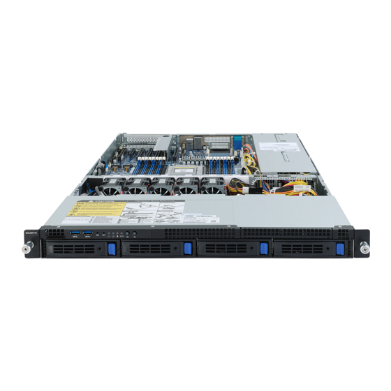
Chapter 2 System Appearance Front View R152-Z30 HDD#0 HDD#1 HDD#2 HDD#3 R152-Z31 HDD#0 HDD#2 HDD#4 HDD#6 HDD#8 HDD#1 HDD#3 HDD#5 HDD#7 HDD#9 R152-Z32 HDD#0 HDD#2 HDD#4 HDD#6 HDD#8 HDD#1 HDD#3 HDD#5 HDD#7 HDD#9 Description Front Panel LEDs and buttons Front USB 3.0 Port Orange HDD Latches Support NVMe •... -
Page 18: Front Panel Led And Buttons
Front Panel LED and Buttons R52-Z30 Name Color Status Description Press the button server generates a NMI to the processor NMI button if the multiple-bit ECC errors occur, which effectively halt the server. Reset Button Press the button to reset the system. Green Solid On Link between system and network or no access. - Page 19 R152-Z31 R152-Z32 Name Color Status Description Reset Button Press the button to reset the system. Press the button server generates a NMI to the processor NMI button if the multiple-bit ECC errors occur, which effectively halt the server. Green System is powered on Green Blink System is in ACPI S1 state (sleep mode)
-
Page 20: Rear System Lan Leds
Rear System LAN LEDs Name Color Status Description Yellow 1 Gbps data rate 1GbE Green 100 Mbps data rate Speed LED 10 Mbps data rate Link between system and 1GbE Green network or no access Link/ Blink Data transmission or receiving is occurring Activity No data transmission or receiving is occurring... -
Page 21: Hard Disk Drive Leds
Hard Disk Drive LEDs R152-Z30 R152-Z31 R152-Z32 HDD Present RAID SKU HDD Fault Rebuilding LED1 Locate Access (No Access) Disk LED Green ON(*1) BLINK (*2) (LED on Back Panel) Amber No RAID configuration ON(*1) Green (via HBA) Removed HDD Slot (LED on Back Panel) Amber BLINK (*2) - Page 22 This page intentionally left blank System Appearance - 22 -...
-
Page 23: Chapter 3 System Hardware Installation
Chapter 3 System Hardware Installation Pre-installation Instructions Computer components and electronic circuit boards can be damaged by discharges of static electricity. Working on computers that are still connected to a power supply can be extremely dangerous. Follow the simple guidelines below to avoid damage to your computer or injury to yourself. -
Page 24: Removing Chassis Cover
Removing Chassis Cover Before you remove or install the system cover • Make sure the system is not turned on or connected to AC power. Follow these instructions to remove the rear system cover: Loosen and remove the thumbscrew securing the back cover. Push down the indentation located at the side of the back chassis Slide the cover horizontally to the back and remove the cover in the direction of the arrow. -
Page 25: Removing And Installing The Fan Duct
Removing and Installing the Fan Duct Follow these instructions to remove/install the fan duct: Lift up to remove the two fan ducts To install the fan duct, align the fan duct with the guiding groove. Push down the fan duct into chassis until its firmly seats R152-Z30 R152-Z31/R152-Z32... -
Page 26: Installing The Cpu And Heat Sink
Installing the CPU and Heat Sink Read the following guidelines before you begin to install the CPU: • Make sure that the motherboard supports the CPU. • Always turn off the computer and unplug the power cord from the power outlet before installing the CPU to prevent hardware damage. - Page 27 - 27 - System Hardware Installation...
-
Page 28: Installing The Memory
Installing the Memory Read the following guidelines before you begin to install the memory: • Make sure that the motherboard supports the memory. It is recommended that memory of the same capacity, brand, speed, and chips be used. • Always turn off the computer and unplug the power cord from the power outlet before installing the memory to prevent hardware damage. -
Page 29: Installing A Memory
3-4-2 Installing a Memory Before installing a memory module, make sure to turn off the computer and unplug the power cord from the power outlet to prevent damage to the memory module. Be sure to install DDR4 DIMMs on this motherboard. Follow these instructions to install the Memory: Insert the DIMM memory module vertically into the DIMM slot, and push it down. - Page 30 LRDIMM Maximum Frequency Supported Table DIMM Frequency (MT/s) DIMMs 1.2V 2S2R Populated 2S4R 3200 3200 2933 Not Supported 2933 3DS RDIMM Maximum Frequency Supported Table DIMM Frequency (MT/s) DIMMs 1.2V 2S2R Populated 2S4R 2933 2666 NOTE! l 1R: 1 package rank of SDP DRAMs l 2R: 2 package rank of SDP DRAMs l 2DR: 2 package rank of DDP DRAMs l 4DR: 4 package rank of DDP DRAMs...
-
Page 31: Installing The Pci Expansion Card
Installing the PCI Expansion Card • Voltages can be present within the server whenever an AC power source is connected. This voltage is present even when the main power switch is in the off position. Ensure that the system is powered-down and all power sources have been disconnected from the server prior to installing a PCI card. - Page 32 R152-Z31/R152-Z32 System Hardware Installation - 32 -...
-
Page 33: Installing The Hard Disk Drive
Installing the Hard Disk Drive Read the following guidelines before you begin to install the Hard disk drive: • Take note of the drive tray orientation before sliding it out. • The tray will not fit back into the bay if inserted incorrectly. •... - Page 34 Follow these instructions to install a 2.5" hard disk drive: Press down the colored release button. Pull out the black locking lever. Use the black locking lever to slide out the HDD tray. Place one side of the HDD at a 45 degree angle into the tray, and align the guiding stand-offs in the tray with the installation holes of the HDD.
-
Page 35: Installing The Mezzanine Card (Optional)
Installing the Mezzanine Card (Optional) Follow these instructions to install a mezzanine card: Insert the mezzanine card into the system ensuring that the connector on the mezzanine card connects to the connector on the motherboard. Secure the mezzanine card to the system with three screws. R152-Z30 R152-Z31/R152-Z32 - 35 -... -
Page 36: Replacing The Fan Assemblly
Replacing the FAN Assemblly Follow these instructions to replace the fan assembly: Lift up the fan assembly from the chassis. Reverse the previous steps to install the replacement fan assembly. R152-Z30 R152-Z31/R152-Z32 System Hardware Installation - 36 -... -
Page 37: Replacing The Power Supply
Replacing the Power Supply Follow these instructions to replace the power supply: Press the retaining clip on the right side of the power supply along the direction of the arrow. Pull up the power supply handle at the same time and pull out the power supply. Insert the replacement power supply firmly into the chassis. -
Page 38: Installing The Mezzanine Card (Optional)
3-10 Installing the Mezzanine Card (Optional) Follow these instructions to install a mezzanine card: Insert the mezzanine card into the system ensuring that the connector on the mezzanine card connects to the connector on the motherboard. Secure the mezzanine card to the system with three screws. NOTE! Supports OCP V2.0 Card. -
Page 39: Cable Routing
3-11 Cable Routing 3-11-1 R152-Z30 Cable Routing Front Switch Cable/Front LED Cable Front Panel USB 3.0 Cable HDD Back Plane Board Power Cable HDD Back Plane Board Signal Cable - 39 - System Hardware Installation... - Page 40 On-Board SATA to HDD Back Plane Board Cable System Hardware Installation - 40 -...
-
Page 41: R152-Z31 Cable Routing
3-11-2 R152-Z31 Cable Routing Front Switch Cable/Front LED Cable Front Panel USB 3.0 Cable HDD Back Plane Board Power Cable HDD Back Plane Board Signal Cable - 41 - System Hardware Installation... - Page 42 On-Board SATA to HDD Back Plane Board On-Board SATA to HDD Back Plane Board Cable (SATA0) Cable (SATA1) U.2 NMVe to HDD Back Plane Board Cable U.2 NMVe to HDD Back Plane Board Cable (NMVe0) (NMVe1) System Hardware Installation - 42 -...
-
Page 43: R152-Z32 Cable Routing
3-11-3 R152-Z32 Cable Routing Front Switch Cable/Front LED Cable Front Panel USB 3.0 Cable HDD Back Plane Board Power Cable HDD Back Plane Board Signal Cable - 43 - System Hardware Installation... - Page 44 U.2 NMVe to HDD Back Plane Board Cable U.2 NMVe to HDD Back Plane Board Cable (NMVe0) (NMVe1) U.2 NMVe to HDD Back Plane Board Cable U.2 NMVe to HDD Back Plane Board Cable (NMVe2) (NMVe3) System Hardware Installation - 44 -...
- Page 45 U.2 NMVe to HDD Back Plane Board Cable U.2 NMVe to HDD Back Plane Board Cable (NMVe4) (NMVe5) U.2 NMVe to HDD Back Plane Board Cable U.2 NMVe to HDD Back Plane Board Cable (NMVe6) (NMVe7) - 45 - System Hardware Installation...
- Page 46 U.2 NMVe to HDD Back Plane Board Cable U.2 NMVe to HDD Back Plane Board Cable (NMVe6) (NMVe7) System Hardware Installation - 46 -...
-
Page 47: Chapter 4 Motherboard Components
Chapter 4 Motherboard Components Motherboard Components 21 22 Item Description SlimLine SAS Connector (U2_0) SlimLine SAS Connector (U2_1) SlimLine SAS Connector (U2_2) SlimLine SAS Connector (U2_3) Front panel USB 3.0 connector Front Panel Connector HDD Back Plane Board Connector M.2 Connector (PCIe3 x4, NGFF-2280) Riser Connector #1 - 47 - Motherboard Components... - Page 48 M.2 Connector (PCIe3 x4, NGFF-2280) USB 2.0 Cable Connector TPM Module Connector Serial Port cable Connector IPMB Connector BMC Firmware Readiness LED Riser Connector SlimLine SAS Connector (SLINK0) SlimLine SAS Connector (SLINK1) SlimLine SAS Connector (SLINK2) SlimLine SAS Connector (SLINK3) OCP Mezzanine Connector System Battery 2 x 13 Pin Power Connector...
-
Page 49: Jumper Settings
Jumper Settings HSMB_SEL BIOS Defined BIOS Defined PMBUS_SEL BIOS_PWD Clear supervisor password Normal [Default] BIOS recovery mode Normal [Default] BIOS_RCVR Default Clear CMOS CLR_CMOS Enable - 49 - Motherboard Components... - Page 50 This page intentionally left blank Motherboard Components - 50 -...
-
Page 51: Chapter 1 Bios Setup
Chapter 1 BIOS Setup BIOS (Basic Input and Output System) records hardware parameters of the system in the EFI on the motherboard. Its major functions include conducting the Power-On Self-Test (POST) during system startup, saving system parameters and loading operating system, etc. BIOS includes a BIOS Setup program that allows the user to modify basic system configuration settings or to activate certain system features. - Page 52 Main This setup page includes all the items in standard compatible BIOS. Advanced This setup page includes all the items of AMI BIOS special enhanced features. (ex: Auto detect fan and temperature status, automatically configure hard disk parameters.) ...
-
Page 53: The Main Menu
The Main Menu Once you enter the BIOS Setup program, the Main Menu (as shown below) appears on the screen. Use arrow keys to move among the items and press <Enter> to accept or enter other sub-menu. Main Menu Help The on-screen description of a highlighted setup option is displayed on the bottom line of the Main Menu. - Page 54 Parameter Description Onboard LAN Information LAN1 MAC Address Displays LAN MAC address information. (Note1) LAN2 MAC Address Displays LAN MAC address information. (Note1) VR Information Version Displays VR version information. AGESA PI Version PI Version Displays AGESA PI version information. Memory Information Total Memory Displays the total memory size of the installed memory.
-
Page 55: Advanced Menu
Advanced Menu The Advanced menu display submenu options for configuring the function of various hardware components. Select a submenu item, then press [Enter] to access the related submenu screen. - 55 - BIOS Setup... -
Page 56: Trusted Computing
5-2-1 Trusted Computing Parameter Description Configuration Select Enabled to activate TPM support feature. Security Device Support Options available: Enabled/Disabled. Default setting is Disabled. SPI TPM Support Options available: Enabled/Disabled. Default setting is Enabled Options available: Enabled/Disabled. Default setting is Disabled. Disable Block Sid BIOS Setup - 56 -... -
Page 57: Psp Firmware Versions
5-2-2 PSP Firmware Versions The PSP Firmware Versions page displays the basic PSP firmware version information. Items on this window are non-configurable. - 57 - BIOS Setup... -
Page 58: Legacy Video Select
5-2-3 Legacy Video Select Parameter Description Select between onboard or external VGA support. OnBrd/Ext VGA Select Options available: Auto/Onboard/External. Default setting is Onboard. BIOS Setup - 58 -... -
Page 59: Ast2500 Super Io Configuration
5-2-4 AST2500 Super IO Configuration Parameter Description AST2500 Super IO Configuration Super IO Chip Serial Port 1/2 Press [Enter] for configuration of advanced items. Configuration - 59 - BIOS Setup... - Page 60 5-2-4-1 Serial Port 1/2 Configuration BIOS Setup - 60 -...
- Page 61 Parameter Description Serial Port 1/2 Configuration Enable/Disable the Serial Port (COM). When set to Enabled allows you to configure the Serial port 1/2 settings. When set to Disabled, displays no Serial Port (Note1) configuration for the serial port. Options available: Enabled/Disabled. Default setting is Enabled. Devices Settings Displays the Serial Port 1/2 device settings.
-
Page 62: S5 Rtc Wake Settings
5-2-5 S5 RTC Wake Settings Parameter Description Enable or disable System wake on alarm event. When enabled, System Wake system from S5 will wake on the hr:min:sec specified. (Note) Default setting is Disabled. Wake up year Press <+> and <-> to define the wake up year. Wake up month Press <+>... -
Page 63: Serial Port Console Redirection
5-2-6 Serial Port Console Redirection Parameter Description Select whether to enable console redirection for specified device. Console COM1/COM2 Serial Over redirection enables the users to manage the system from a remote LAN Console Redirection location. (Note) Options available: Enabled/Disabled. Default setting is Disabled. Selects a COM port for Legacy serial redirection. - Page 64 Parameter Description Bits per second Š – Selects the transfer rate for console redirection. – Options available: 9600/19200/38400/57600/115200. Default setting is 115200. Data Bits Š – Selects the number of data bits used for console redirection. – Options available: 7/8. Default setting is 8. Parity Š...
-
Page 65: Cpu Configuration
5-2-7 CPU Configuration Parameter Description Enable/disable the CPU Virtualization. SVM Mode Options available: Enabled/Disabled. Default setting is Enabled. Controls the Secure Memory Encryption Enable (SMEE) function. SMEE Options available: Enabled/Disabled. Default setting is Enabled. CPU 0 Information Press [Enter] to view the memory information related to CPU 0. - 65 - BIOS Setup... - Page 66 5-2-7-1 CPU 0 Information BIOS Setup - 66 -...
-
Page 67: Pci Subsystem
5-2-8 PCI Subsystem Parameter Description PCI Bus Driver Version Displays the PCI Bus Driver version information. Change the PCIe lanes. PCIE_# Options available: Auto/x16/x8x8/x8x4x4/x4x4x8/x4x4x4x4/ (Note1) Disabled. Default setting is Auto. When enabled, this setting will initialize the device expansion PCI Express Slot # I/O ROM ROM for the related PCI-E slot. - Page 68 Parameter Description PCI Devices Common Settings Enable/Disable memory mapped I/O to 4GB or greater address Above 4G Decoding space (Above 4G Decoding). Options available: Enabled/Disabled. Default setting is Enabled. If the system has SR-IOV capable PCIe devices, this item SR-IOV Support Enable/Disable Single Root IO Virtualization Support.
-
Page 69: Usb Configuration
5-2-9 USB Configuration Parameter Description USB Configuration USB Controller Displays the supported USB controllers. USB Devices: Displays the USB devices connected to the system. Enable/disable the Legacy USB support fuction. AUTO option disables legacy support if no USB devices are connected. DISABLE option will Legacy USB Support keep USB devices available only for EFI applications. - Page 70 Maximum time the device will take before it properly reports itself to the Host Controller. "Auto" uses default value: for a Root port it is 100 Device power-up delay ms, for a Hub port the delay is taken from Hub descriptor. Options available: Auto/Manual.
-
Page 71: Nvme Configuration
5-2-10 NVMe Configuration Parameter Description NVMe controller and Drive Displays the NVMe devices connected to the system. Information - 71 - BIOS Setup... -
Page 72: Sata Configuration
5-2-11 SATA Configuration BIOS Setup - 72 -... -
Page 73: Network Stack
5-2-12 Network Stack Parameter Description Enable/Disable the UEFI network stack. Network Stack Options available: Enabled/Disabled. Default setting is Enabled. Enable/Disable the Ipv4 PXE feature. Ipv4 PXE Support (Note) Options available: Enabled/Disabled. Default setting is Enabled. Enable/Disable the Ipv4 HTTP feature. Ipv4 HTTP Support (Note) Options available: Enabled/Disabled. -
Page 74: Amd Mem Configuration Status
5-2-13 AMD Mem Configuration Status Parameter Description CPU0 Press [Enter] for configuration of advanced items. BIOS Setup - 74 -... -
Page 75: Iscsi Configuration
5-2-14 iSCSI Configuration Parameter Description iSCSI Initiator Name Add Attempt Press [Enter] for configuration of advanced items. Delete Attempt Press [Enter] for configuration of advanced items. Change Attempt Order Press [Enter] for configuration of advanced items. - 75 - BIOS Setup... -
Page 76: Tls Auth Configuration
5-2-15 Tls Auth Configuration Parameter Description Save CA Configuration Press [Enter] for configuration of advanced items. Client Cert Configuration Press [Enter] for configuration of advanced items. BIOS Setup - 76 -... -
Page 77: Avago Megaraid Configuration Utility
5-2-16 AVAGO MegaRAID Configuration Utility - 77 - BIOS Setup... - Page 78 Parameter Description Main Menu Press [Enter] for configuration of advanced items. Help Press [Enter] for configuration of advanced items. PROPERTIES Status Current Personality Backplane Enclosure Drives Drive Gropus Virtual Drives View Server Profile Press [Enter] for configuration to view Server Profile. Action Configure Press [Enter] for configuration of advanced items.
-
Page 79: Intel(R) I350 Gigabit Network Connection
5-2-17 Intel(R) I350 Gigabit Network Connection - 79 - BIOS Setup... - Page 80 Parameter Description Press [Enter] to configure advanced items. Link Speed Š – Allows for automatic link speed adjustment. – Options available: Auto Negotiated/10 Mbps Half/10 Mbps Full/100 Mbps Half/100 Mbps Full. Default setting is Auto Negotiated. NIC Configuration Wake On LAN Š...
-
Page 81: Vlan Configuration
5-2-18 VLAN Configuration - 81 - BIOS Setup... - Page 82 Parameter Description Press [Enter] to configure advanced items. Create new VLAN Š VLAN ID Š – Sets VLAN ID for a new VLAN or an existing VLAN. – Press the <+> / <-> keys to increase or decrease the desired values. –...
-
Page 83: Mac Ipv4 Network Configuration
5-2-19 MAC IPv4 Network Configuration Parameter Description Options available: Enabled/Disabled. Default setting is Enabled. Configured Options available: Enabled/Disabled. Default setting is Enabled. Enable DHCP Local IP Address Press [Enter] to configure local IP address. Local NetMask Press [Enter] to configure local NetMask. Local Gateway Press [Enter] to configure local Gateway Local DNS Servers... -
Page 84: Mac Ipv6 Network Configuration
5-2-20 MAC IPv6 Network Configuration Parameter Description Enter Configuration Menu Press [Enter] for configuration of advanced items. BIOS Setup - 84 -... -
Page 85: Amd Cbs Menu
AMD CBS Menu AMD CBS menu displays submenu options for configuring the CPU-related information that the BIOS automatically sets. Select a submenu item, then press [Enter] to access the related submenu screen. - 85 - BIOS Setup... -
Page 86: Valhalla Common Options
5-3-1 Valhalla Common Options Parameter Description Performance Press [Enter] for configuration of advanced items. Prefetcher settings Press [Enter] for configuration of advanced items. Core Watchdog Press [Enter] for configuration of advanced items. RedirectForReturnDis Options available: Auto/1/0. Default setting is Auto. Platform First Error Warning Options available: Auto/Enabled/Disabled. - Page 87 Parameter Description Options available: Auto/Enabled/Disabled. Default setting is Auto. SMU and PSP Debug Mode Options available: Auto/No Workaround/ Bronze Workaround/ Sliver Xtrig7 Workaround Workaround. Default setting is Auto. Options available: Auto/Enabled/Disabled. Default setting is Auto. PPIN Opt-in - 87 - BIOS Setup...
-
Page 88: Df Common Options
5-3-2 DF Common Options Parameter Description Scrubber Press [Enter] for configuration of advanced items. Memory Addressing Press [Enter] for configuration of advanced items. ACPI Press [Enter] for configuration of advanced items. Link Press [Enter] for configuration of advanced items. Disable DF to external IP Options available: Auto/Sync flood disabled/Sync flood enabled. -
Page 89: Umc Common Options
5-3-3 UMC Common Options Parameter Description DDR4 Common Options Press [Enter] for configuration of advanced items. DRAM Memory Mapping Press [Enter] for configuration of advanced items. NVDIMM Press [Enter] for configuration of advanced items. Memory MBIST Press [Enter] for configuration of advanced items. - 89 - BIOS Setup... - Page 90 5-3-3-1 DDR4 Common Options Parameter Description Enforce POR Press [Enter] to configure the enforce POR. DRAM Controller Press [Enter] to configure the DRAM controller. Configuration CAD Bus Configuration Press [Enter] to configure the cad bus. Data Bus Configuration Press [Enter] to configure the data bus. Common RAS Press [Enter] to configure the common RAS.
- Page 91 5-3-3-2 DRAM Memory Mapping Parameter Description Interleave memory blocks across the DRAM chip selects for CPU 0. Chipselect Interleaving Options available: Disabled/Auto. Default setting is Auto. Configures the BankGroupSwap. BankGroupSwap (BGS) is a new memory mapping option in AGESA that alters how applications get BankGroupSwap assigned to physical locations within the memory modules.
- Page 92 5-3-3-3 NVDIMM BIOS Setup - 92 -...
- Page 93 5-3-3-4 Memory MBIST Parameter Description Options available: Enabled/Disabled. Default setting is Disabled. MBIST Enable Options available: Interface Mode/Data Eye Mode/Both/Auto. Default MBIST Test Mode (Note) setting is Auto. Options available: Auto/Enabled/Disabled. Default setting is Auto. MBIST Aggressors (Note) MBIST Per Bit Slave Die Options available: Auto/Enabled/Disabled.
-
Page 94: Nbio Common Options
5-3-4 NBIO Common Options Parameter Description Options available: Enabled/Disabled. Default setting is Disabled. IOMMU Options available: Auto/Enabled/Disabled. Default setting is Auto. ACS Enable PCIe ARI Support Options available: Auto/Enabled/Disabled. Default setting is Auto. Options available: Auto/Enabled/Disabled. Default setting is Auto. PCIe Ten Bit Tag Support HD Audio Enable Press [Enter] for configuration of advanced items. -
Page 95: Fch Common Options
5-3-5 FCH Common Options Parameter Description SATA Configuration Options Press [Enter] for configuration of advanced items. USB Configuration Options Press [Enter] for configuration of advanced items. SD Dump Options Press [Enter] for configuration of advanced items. AC Power Loss Options Press [Enter] to configure the AC loss control. -
Page 96: Ntb Common Options
5-3-6 NTB Common Options Parameter Description Options available: Auto/Enabled. Default setting is Auto. BIOS Setup - 96 -... -
Page 97: Soc Miscellaneous Control
5-3-7 SOC Miscellaneous Control Parameter Description Options available: Auto/Enabled/Disabled. Default setting is Auto. ABL Console Out Control ABL PMU message Options available: Auto/Enabled/Disabled. Default setting is Auto. Control (Note) This item appears when ABL Console Out Control is set to Enabled. (Note) - 97 - BIOS Setup... -
Page 98: Amd Pbs Option Menu
AMD PBS Option Menu AMD PBS Option menu displays submenu options for configuring the function of AMD PBS. Select a submenu item, then press [Enter] to access the related submenu screen. Parameter Description Press [Enter] for configuration of advanced items. SPI Locking Options available: Enabled/Disabled. -
Page 99: Ras
5-4-1 RAS Parameter Description RAS Periodic SMI Control Options available: Enabled/Disabled. Default setting is Disabled. SMI Threshold Set the SMI Threshold value. SMI Scale Set the SMI Scale value. Options available: millisecond/second/minute. Default setting is SMI Scale Unit millsecond. SMI Period Set the SMI Period. - Page 100 Parameter Description PCIe Device Corr Err Mask Initialize the PCIe AER Corrected Error Mask register of PCIe device. PCIe Device UnCorr Err Mask Initialize the PCIe AER Uncorrected Error Mask register of PCIe device. PCIe Device UnCorr Err Sev Initialize the PCIe AER Uncorrected Error Serverity register of PCIe device.
-
Page 101: Chipset Setup Menu
Chipset Setup Menu Chipset Setup menu displays submenu options for configuring the function of the North Bridge. Select a submenu item, then press [Enter] to access the related submenu screen. Parameter Description PCIe Link training in 1 or 2 steps. PCIe Link Training Type Options available: 1 Step/2Step. -
Page 102: North Bridge
5-5-1 North Bridge Parameter Description Memory Information Total Memory Displays the total memory information. CPU0 Information Press [Enter] to view information related to CPU 0. BIOS Setup - 102 -... -
Page 103: Server Management Menu
Server Management Menu Parameter Description Enable/Disable FRB-2 timer (POST timer). FRB-2 Timer Options available: Enabled/Disabled. Default setting is Disabled. Configure the FRB2 Timer timeout. Options available: 3 minutes/4 minutes/5 minutes/6 minutes. Default setting is 6 FRB-2 Timer timeout minutes. Please note that this item is configurable when FRB-2 Timer is set to Enabled. Configure the FRB2 Timer policy. - Page 104 Parameter Description System Event Log Press [Enter] to configure advanced items. View FRU Press [Enter] to view the advanced items. Information BMC network Press [Enter] to configure advanced items. configuration IPv6 BMC Network Press [Enter] to configure advanced items. Configuration BIOS Setup - 104 -...
-
Page 105: System Event Log
5-6-1 System Event Log Parameter Description Enabling / Disabling Options Change this item to enable or disable all features of System Event SEL Components Logging during boot. Options available: Enabled/Disabled. Default setting is Enabled. Erasing Settings Choose options for erasing SEL. Erasing SEL Options available: No/Yes, On next reset/Yes, On every reset. -
Page 106: View Fru Information
5-6-2 View FRU Information The FRU page is a simple display page for basic system ID information, as well as System product information. Items on this window are non-configurable. (Note) The model name will vary depends on the product you purchased. BIOS Setup - 106 -... -
Page 107: Bmc Network Configuration
5-6-3 BMC Network Configuration Parameter Description BMC network configuration Lan Channel 1 Select to configure LAN channel parameters statically or dynamically (DHCP). Do nothing option will not modify any BMC network parameters Configuration Address source during BIOS phase. Options available: Unspecified/Static/DynamicBmcDhcp. Default setting is DynamicBmcDhcp. -
Page 108: Ipv6 Bmc Network Configuration
5-6-4 IPv6 BMC Network Configuration Parameter Description IPv6 BMC Network Configuration IPv6 BMC Lan Channel 1 Enable/Disable IPv6 BMC LAN channel function. When this item is disabled, the system will not modify any BMC network during BIOS IPv6 BMC Lan Option phase. -
Page 109: Security Menu
Security Menu The Security menu allows you to safeguard and protect the system from unauthorized use by setting up access passwords. There are two types of passwords that you can set: • Administrator Password Entering this password will allow the user to access and change all settings in the Setup Utility. •... -
Page 110: Secure Boot
5-7-1 Secure Boot Parameter Description System Mode Displays the system is in User mode or Setup mode. Secure Boot requires all the applications that are running during the booting process to be pre-signed with valid digital certificates. This way, the system knows all the files being loaded before Windows loads and gets to the login screen have not been tampered with. - Page 111 Parameter Description Press [Enter] to configure advanced items. Please note that this item is configurable when Secure Boot Mode is set to Custom. Provision Factory Defaults Š – Allows to provision factory default Secure Boot keys when system is in Setup Mode.
-
Page 112: Boot Menu
Boot Menu The Boot menu allows you to set the drive priority during system boot-up. BIOS setup will display an error message if the legacy drive(s) specified is not bootable. Parameter Description Boot Configuration Number of seconds to wait for setup activation key. 65535 (0xFFFF) Setup Prompt Timeout means indefinite waiting. - Page 113 Parameter Description FIXED BOOT ORDER Priorities Press [Enter] to configure the boot priority. By default, the server searches for boot devices in the following sequence: Boot Option #1 / #2 / #3 / #4 / Hard drive. CD-COM/DVD drive. USB device. Network.
-
Page 114: Save & Exit Menu
Save & Exit Menu The Exit menu displays the various options to quit from the BIOS setup. Highlight any of the exit options then press Enter. Parameter Description Save Options Saves changes made and closes the BIOS setup. Save Changes and Exit Options available: Yes/No. -
Page 115: Abl Post Codes
5-10 ABL POST Codes 5-10-1 StartProcessorTestPoints Entry used for range testing for @b Processor related TPs 0xE000 5-10-2 Memory test points Memory structure initialization (Public interface) 0xE001 SPD Data processing (Public interface) 0xE002 Memory configuration (Public interface) Phase 1 0xE003 DRAM initialization 0xE004 ProcMemSPDChecking... -
Page 116: Original Post Code
ABL Mem - PMU Stage Training Wr 2D 0xE023 ABL Mem - PMU Queue Empty 0xE024 ABL Mem - PMU US message Start 0xE025 ABL Mem - PMU US message End 0xE026 ABL Mem - PMU Complete 0xE027 ABL Mem - PMU - After PMU Training 0xE028 ABL Mem - PMU - Before Disable PMU 0xE029... -
Page 117: Cpu Test Points
ABL Mem - Before OtherTiming 0xE04A ABL Mem - Before UMAMemTyping 0xE04B ABL Mem - Before SetDqsEccTmgs 0xE04C ABL Mem - Before MemClr 0xE04D ABL Mem - Before On DIMM Thermal 0xE04E ABL Mem - Before DMI 0xE04F ABL MEM - End of phase 3 memory code 0xE050 5-10-5 CPU test points Entry point CPU init after training... -
Page 118: Gnb Earlier Init
5-10-8 Gnb Earlier init TP0x90 0xE090 GNB earlier interface 0xE091 GNB internal debug code 0xE092 GNB internal debug code 0xE093 GNB internal debug code 0xE094 GNB internal debug code 0xE095 GNB internal debug code 0xE096 GNB internal debug code 0xE097 GNB internal debug code 0xE098 GNB internal debug code... - Page 119 ABL 2 Begin 0xE0B8 ABL 2 Initialization 0xE0B9 ABL 2 After Training 0xE0BA ABL 2 Debug Synchronization 0xE0BB ABL 2 Error detected 0xE0BC ABL 2 Global memory error detected 0xE0BD ABL 2 End 0xE0BE ABL 3 Begin 0xE0BF ABL 3 Initialziation 0xE0C0 ABL 3 GMI/xGMI Initialization Stage 1 0xB1C0...
- Page 120 ABL 4 APOB Initialzation - cold boot 0xE0CA ABL 4 Finalize memory settings - cold boot 0xE0CB ABL 4 CPU Initialize Optimized Boot - cold boot 0xE0CC ABL 4 Gmi Pcie Training - cold boot 0xE0CD ABL 4 Cold boot End 0xE0CE ABL 4 Initialization - Resume boot 0xE0CF...
-
Page 121: Pmu Test Points
Before the memory code calls out to locate a buffer 0xE0F3 After the memory code calls out to locate a buffer 0xE0F4 Before the memory code calls out to locate a buffer 0xE0F5 After the memory code calls out to locate a buffer 0xE0F6 Before the memory code calls out to locate a buffer 0xE0F7... - Page 122 ABL Error for Soc Scan No Die error 0xE2AC ABL Error for Nb Tech Heap Aloc error 0xE2AD ABL Error for No Nb Constructor error 0xE2AE ABL Error for No Tech Constructor error 0xE2AE ABL Error for ABL1b Auto Alocation error 0xE2B0 ABL Error for ABL1b No NB Constructor error 0xE2B1...
- Page 123 ABL Error over clock Mem Init Error 0xE2D5 ABL Error over clock Mem Other Error 0xE2D6 ABL Error for ABL6 General Error 0xE2D7 ABL Error Event Log Error 0xE2D8 ABL Error FATAL ABL1 Log Error 0xE2D9 ABL Error FATAL ABL2 Log Error 0xE2DA ABL Error FATAL ABL3 Log Error 0xE2DB...
- Page 124 ABL Error ABL 2 Mem Init Error 0xE302 ABL Error ABL 4 Mem Init Error 0xE303 ABL Error ABL 6 Mem Init Error 0xE304 ABL Error ABL 1 error repor Error 0xE305 ABL Error ABL 2 error repor Error 0xE306 ABL Error ABL 3 error repor Error 0xE307 ABL Error ABL 4 error repor Error...
-
Page 125: Agesa Post Codes
5-11 Agesa POST Codes 5-11-1 Universal Post Code Universal ACPI entry 0xA001 Universal ACPI exit 0xA002 Universal ACPI abort 0xA003 Universal SMBIOS entry 0xA004 Universal SMBIOS exit 0xA005 Universal SMBIOS abort 0xA006 5-11-2 [0xA1XX] For CZ only memory Postcodes Memory structure initialization (Public interface) 0xA101 SPD Data processing (Public interface) 0xA102... - Page 126 Calculate MaxRdLatency per channel 0xA120 TpProcMemReceiveDqsTraining 0xA121 Set Write Data delay 0xA122 Write test pattern 0xA123 Start read sweep 0xA124 Set Receive DQS delay 0xA125 Read Test pattern 0xA126 Compare Test pattern 0xA127 Update results 0xA128 Start Find passing window 0xA129 TpProcMemTransmitDqsTraining 0xA12A...
- Page 127 Before InitMCT 0xA149 Before OtherTiming 0xA14A Before UMAMemTyping 0xA14B Before SetDqsEccTmgs 0xA14C Before MemClr 0xA14D Before On DIMM Thermal 0xA14E Before DMI 0xA14F End of memory code 0xA150 Entry point S3Init 0xA151 Sending MRS2 0xA180 Sedding MRS3 0xA181 Sending MRS1 0xA182 Sending MRS0 0xA183...
-
Page 128: S3 Interface Post Code
BR Init Mid end 0xA19E BR Init Late entry 0xA19F BR Init Late install protocol 0xA1A0 BR Init Late end 0xA1A1 BR DXE install complete protocol 0xA1A2 UNB install complete PPI 0xA1A3 UNB AfterApLaunch callback entry 0xA1A4 UNB AfterApLaunch callback end 0xA1A5 5-11-3 S3 Interface Post Code Before the S3 save code calls out to allocate a buffer... - Page 129 PspSmmV1 SwSmiCallBack exit, build the S3 save area for resume 0xA511 PspSmmV1 BspSmmResumeVector entry 0xA512 PspSmmV1 BspSmmResumeVector exit 0xA513 PspSmmV1 ApSmmResumeVector entry 0xA514 PspSmmV1 ApSmmResumeVector exit 0xA515 PspP2CmboxV1 entry 0xA516 PspP2CmboxV1 exit 0xA517 // PSP V2 Modules PspPeiV2 entry 0xA521 PspPeiV2 exit 0xA522 PspDxeV2 entry...
- Page 130 PspP2Cmbox Command SpiSetAttrib Handling entry 0xA592 PspP2Cmbox Command SpiGetBlockSize Handling entry 0xA593 PspP2Cmbox Command SpiReadFV Handling entry 0xA594 PspP2Cmbox Command SpiWriteFV Handling entry 0xA595 PspP2Cmbox Command SpiEraseFV Handling entry 0xA596 PspP2Cmbox Command Handling exit 0xA59E PspP2Cmbox Command Handling Fail exit 0xA59F // C2P mailbox Handling PSP C2P mailbox entry base [0xA5BX | Cmd]...
-
Page 131: 0Xa9Xx, 0Xaaxx] Assigned For Agesa Nbio Module
5-11-6 [0xA9XX, 0xAAXX] assigned for AGESA NBIO Module // NbioBase AmdNbioBase PEIM driver entry 0xA900 AmdNbioBase PEIM driver exit 0xA901 AmdNbioBase DXE driver entry 0xA902 AmdNbioBase DXE driver exit 0xA903 // PCIe AmdNbioPcie PEIM driver entry 0xA904 AmdNbioPcie PEIM driver exit 0xA905 AmdNbioPcie DXE driver entry 0xA906... - Page 132 // APCB SMM APCB SMM Entry 0xA924 APCB SMM Exit 0xA925 // [0xA950, 0xA99F] NBIO PPI/PROTOCOL Callback NbioTopologyConfigureCallback entry 0xA950 NbioTopologyConfigureCallback exit 0xA951 MemoryConfigDoneCallbackPpi entry 0xA952 MemoryConfigDoneCallbackPpi exit 0xA953 DxioInitializationCallbackPpi entry 0xA954 DxioInitializationCallbackPpi exit 0xA955 DispatchSmuV9Callback entry 0xA956 DispatchSmuV9Callback exit 0xA957 DispatchSmuV10Callback entry 0xA958...
-
Page 133: 0Xacxx] Assigned For Agesa Ccx Module
GfxConfigEnvInterface entry 0xA984 GfxConfigEnvInterface exit 0xA985 GfxEnvInterfaceCZ entry 0xA986 GfxEnvInterfaceCZ exit 0xA987 GfxMidInterfaceCZ entry 0xA988 GfxMidInterfaceCZ exit 0xA989 GfxIntInfoTableInterfaceCZ entry 0xA98A GfxIntInfoTableInterfaceCZ exit 0xA98B PcieMidInterfaceCZ entry 0xA98C PcieMidInterfaceCZ exit 0xA98D GnbMidInterfaceCZ entry 0xA98E GnbMidInterfaceCZ exit 0xA98F GnbSmuMidInterfaceCZ entry 0xA990 GnbSmuMidInterfaceCZ exit 0xA991 InvokeAmdInitLate entry 0xA992... -
Page 134: 0Xadxx] Assigned For Agesa Df Module
5-11-8 [0xADXX] assigned for AGESA DF Module DF PEI entry 0xAD50 DF DXE entry 0xAD55 DF Ready to Boot entry 0xAD56 DF PEI exit 0xADE0 DF DXE exit 0xADE5 DF Ready to Boot exit 0xADE6 5-11-9 [0xAFXX] assigned for AGESA FCH Module FCH InitReset dispatch point 0xAF01 FCH InitEnv dispatch point... - Page 135 FCH InitEnv AB Link 0xAF51 FCH InitEnv LPC 0xAF52 FCH InitEnv SPI 0xAF53 FCH InitEnv eSPI 0xAF54 FCH InitEnv SD 0xAF55 FCH InitEnv eMMC 0xAF56 FCH InitEnv SATA 0xAF57 FCH InitEnv USB 0xAF58 FCH InitEnv xGbE 0xAF59 FCH InitEnv HwAcpiP 0xAF5F FCH InitMid HwAcpi 0xAF60...
-
Page 136: Bios Post Beep Code (Ami Standard)
5-12 BIOS POST Beep code (AMI standard) 5-12-1 PEI Beep Codes # of Beeps Description Memory not Installed. Memory was installed twice (InstallPeiMemory routine in PEI Core called twice) Recovery started DXEIPL was not found DXE Core Firmware Volume was not found Recovery failed S3 Resume failed Reset PPI is not available... -
Page 137: Bios Recovery Instruction
5-13 BIOS Recovery Instruction The system has an embedded recovery technique. In the event that the BIOS becomes corrupt the boot block can be used to restore the BIOS to a working state. To restore your BIOS, please follow the instructions listed below: Recovery Instruction: Change xxx.ROM to amiboot.rom.