Table of Contents
Advertisement
Quick Links
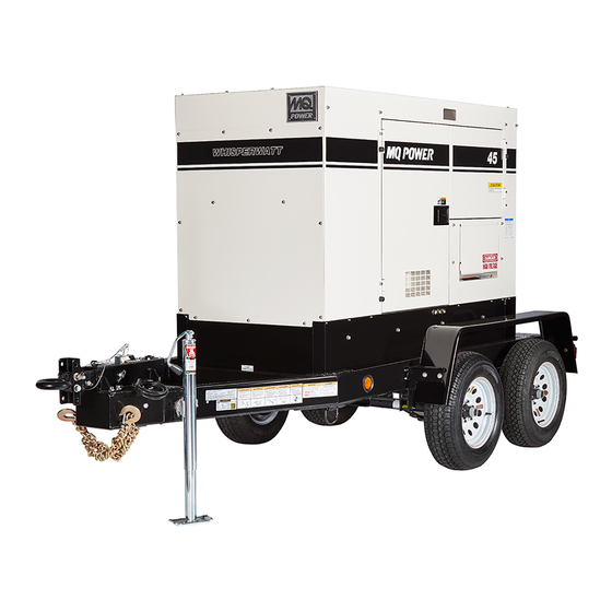
OPERATION MANUAL
WHISPERWATT™ SERIES
MODEL
DCA45SSIU4FC8
60 Hz GENERATOR
(ISUZU 4LE2X DIESEL ENGINE)
INSTRUCTION MANUAL NO. M1844300804A
Revision #0 (08/23/22)
To find the latest revision of this publication or
associated parts manual, visit our website at:
www.mqpower.com
THIS MANUAL MUST ACCOMPANY THE EQUIPMENT AT ALL TIMES.
Advertisement
Table of Contents
Troubleshooting

Related Manuals for MQ Power WHISPERWATT DCA45SSIU4FC8


Summary of Contents for MQ Power WHISPERWATT DCA45SSIU4FC8
- Page 1 OPERATION MANUAL WHISPERWATT™ SERIES MODEL DCA45SSIU4FC8 60 Hz GENERATOR (ISUZU 4LE2X DIESEL ENGINE) INSTRUCTION MANUAL NO. M1844300804A Revision #0 (08/23/22) To find the latest revision of this publication or associated parts manual, visit our website at: www.mqpower.com THIS MANUAL MUST ACCOMPANY THE EQUIPMENT AT ALL TIMES.
-
Page 2: Proposition 65 Warning
PROPOSITION 65 WARNING PAGE 2 — DCA45SSIU4FC8 60 HZ GENERATOR • OPERATION MANUAL — REV. #0 (08/23/22) -
Page 3: Table Of Contents
TABLE OF CONTENTS DCA45SSIU4FC8 60 Hz Generator Proposition 65 Warning ........... 2 Table of Contents ............. 3 Safety Decals ............4 Safety Information ..........5–10 Specifications ............11 Dimensions ............12 Installation ............14–15 General Information ..........16 Major Components ..........17 Control and Operation Panel ...... -
Page 4: Safety Decals
SAFETY DECALS Safety decals are attached to the generator as shown in NOTICE Figure 1. Keep these safety decals clean at all times. When For safety decal part numbers, refer to the associated the safety decals become worn or damaged, contact your parts manual. -
Page 5: Safety Information
SAFETY INFORMATION Do not operate or service the generator before reading the Potential hazards associated with the operation of this entire manual. Safety precautions should be followed at all generator will be referenced with hazard symbols which times when operating this generator. Failure to read and may appear throughout this manual in conjunction with understand the safety messages and operating instructions safety messages. - Page 6 „ NEVER use accessories or attachments that are not being used. The generator should be stored in a clean, dry location out of the reach of children and unauthorized recommended by MQ Power for this generator. Damage to the generator and/or injury to the user may result. personnel.
- Page 7 SAFETY INFORMATION ENGINE SAFETY „ Operation of the generator may create sparks that can start fi res around dry vegetation. A spark arrestor DANGER may be required. The operator should contact local fi re agencies for laws or regulations relating to fi re prevention „...
- Page 8 „ The trailer should be adjusted to a level position at all times when towing. „ Refer to the MQ Power trailer manual for additional safety information. „ Raise and lock the trailer wheel stand in the upright position when towing.
- Page 9 SAFETY INFORMATION ELECTRICAL SAFETY „ Make sure power cables are securely connected to the generator’s output receptacles. Incorrect connections DANGER may cause electrical shock and damage to the generator. „ NEVER touch the output terminals NOTICE during operation. Contact with the „...
- Page 10 SAFETY INFORMATION EMISSIONS INFORMATION „ If the battery liquid (dilute sulfuric acid) comes into contact with eyes, rinse eyes immediately with plenty NOTICE of water and contact the nearest doctor or hospital to seek medical attention. The diesel engine used in this equipment has been designed to reduce harmful levels of carbon monoxide CAUTION (CO), hydrocarbons (HC), and nitrogen oxides (NOx)
-
Page 11: Specifications
SPECIFICATIONS Table 1. Generator Specifications Model DCA45SSIU4FC8 Type Revolving field, protected type synchronous generator Armature Connection Star with Neutral Zigzag Phase Standby Output 39.6 kW (49.5 kVA) 28.6 kW Prime Output 36 kW (45 kVA) 26 kW 3Ø Voltage (L-L/L-N) 208Y/120, 220Y/127, 240Y/139 Voltage Selector Switch at 3Ø... -
Page 12: Dimensions
DIMENSIONS MAXIMUM LIFTING POINT 6,960 lb. (3,157 kg) Figure 2. Dimensions Table 3. Dimensions Denyo Reference Dimension in. (mm) Reference Letter Dimension in. (mm) Letter 28.35 (720) 26.18 (665) 28.35 (720) 83.86 (2,130) 26.18 (665) 63.0 (1,600) 32.28 (820) 37.4 (950) PAGE 12 —... - Page 13 NOTES DCA45SSIU4FC8 60 HZ GENERATOR • OPERATION MANUAL — REV. #0 (08/23/22) — PAGE 13...
-
Page 14: Installation
GENERATOR GROUND LUG GROUND ROD GROUND CABLE REFERENCE NEC 250 Figure 3. Typical Generator Grounding Application NOTICE Trailer-mounted generators are the sole responsibility of MQ Power. PAGE 14 — DCA45SSIU4FC8 60 HZ GENERATOR • OPERATION MANUAL — REV. #0 (08/23/22) - Page 15 INSTALLATION OUTDOOR INSTALLATION MOUNTING Install the generator in an area that is free of debris, The generator must be mounted on a solid foundation bystanders, and overhead obstructions. Make sure the (such as concrete) and set firmly on the foundation to generator is on secure, level ground so that it cannot slide isolate vibration of the generator when it is running.
-
Page 16: General Information
„ Warning (Diagnostic) Lamp Refer to Table 2 for engine specifications. „ Pre-Heat Lamp In keeping with MQ Power’s policy of constantly improving „ Panel Light / Panel Light Switch its products, the specifications quoted herein are subject „ Control Box (located behind control panel) to change without prior notice. -
Page 17: Major Components
MAJOR COMPONENTS Table 4. Major Components ITEM NO. DESCRIPTION Muffler Assembly Voltage Selector Switch Assembly Output Terminal Panel Assembly Emergency Stop Switch Assembly Generator Assembly Engine Assembly Coolant Drain Assembly Fuel Tank Assembly Oil Drain Assembly Control and Operation Panel Assembly Controller/Gauge Unit Assembly Battery Assembly Main Circuit Breaker Assembly... -
Page 18: Control And Operation Panel
CONTROL AND OPERATION PANEL Integrated Gauge Control Low Oil Pressure High Temp Over Crank Over Speed n/min n/min Engine Started Fuel Integrated Gauge Control Low Oil Pressure High Temp Over Crank Over Speed n/min n/min Engine Started Fuel Figure 5. Control And Operation Panel The definitions below describe the controls and functions of the control and operation panel (Figure 5). - Page 19 CONTROL AND OPERATION PANEL 2. Panel Light Switch — Turns the panel light ON/OFF. After running the engine at idling speed for approximately Make sure the Panel Light switch is in the OFF position 15 minutes, place the Engine Speed switch in the High when the light is not needed.
-
Page 20: Output Terminal Panel Familiarization
OUTPUT TERMINAL PANEL FAMILIARIZATION OUTPUT TERMINAL PANEL OUTPUT TERMINAL FAMILIARIZATION The output terminal panel (Figure 6) is provided with the The output terminal panel (Figure 6) shown below is following: provided for the connection of electrical loads. Lift up on the cover to gain access to receptacles and terminal lugs. - Page 21 OUTPUT TERMINAL PANEL FAMILIARIZATION 120-Volt AC GFCI Receptacles CS6369 TWIST-LOCK RECEPTACLES NOTICE It is recommended that the GFCI receptacles be tested when the generator is initially uncrated. The receptacles should then be tested daily at startup. SINGLE-PHASE 240/120 VAC 50 AMP OUTPUT There are two 120-volt, 20-amp GFCI (duplex NEMA Figure 8.
- Page 22 OUTPUT TERMINAL PANEL FAMILIARIZATION Connecting Loads Overcurrent Relay An overcurrent relay (Figure 11) is connected to the Loads can be connected to the generator by the output terminal lugs, convenience receptacles, or optional main circuit breaker. In the event of an overload, both the cam-loks (Figure 10).
-
Page 23: Load Application
LOAD APPLICATION SINGLE-PHASE LOAD THREE-PHASE LOAD Always be sure to check the nameplate on the generator When calculating the power requirements for 3-phase and equipment to ensure the wattage, amperage, frequency, power use the following equation: and voltage requirements are satisfactorily supplied by the VOLTAGE ×... -
Page 24: Generator Outputs
GENERATOR OUTPUTS GENERATOR OUTPUT VOLTAGES MAXIMUM AMPS Table 8 shows the maximum amps the generator can A wide range of voltages (Table 7) is available for many different applications. provide. DO NOT exceed the maximum amps as listed. Table 7. Voltages Available Table 8. -
Page 25: Gauge Reading
GAUGE READING HOW TO READ THE AC AMMETER AND AC VOLTMETER GAUGES The AC ammeter and AC voltmeter gauges are controlled by the AC ammeter and AC voltmeter change-over switches. Both of these switches are located on the control panel and Figure 16. -
Page 26: Output Terminal Panel Connections
OUTPUT TERMINAL PANEL CONNECTIONS UVWO TERMINAL OUTPUT VOLTAGES 3. Tur n the Voltage Regulator control knob (Figure 21) clockwise to increase voltage output, Various output voltages can be obtained using the UVWO counterclockwise to decrease voltage output. Use output terminal lugs. The voltages at the terminals are the Voltage Regulator control knob whenever fine dependent on the position of the Voltage Selector switch tuning of the output voltage is required. - Page 27 OUTPUT TERMINAL PANEL CONNECTIONS 3-Phase 480/277-Volt Single-Phase 240/120-Volt UVWO Terminal Output Voltages UVWO Terminal Output Voltages 1. Place the Voltage Selector switch in the 3-phase 1. Place the Voltage Selector switch in the 1-phase 480/277-volt position as shown in Figure 23. 240/120-volt position as shown in Figure 25.
-
Page 28: Inspection/Setup
INSPECTION/SETUP ENGINE OIL CHECK NOTICE 1. To check the engine oil level, place the generator on When adding engine oil DO NOT overfill (Figure 28B). secure, level ground with the engine stopped. 2. Remove the engine oil dipstick from its holder (Figure 27) and wipe it clean. - Page 29 INSPECTION/SETUP FUEL CHECK Refueling Procedure DANGER WARNING Diesel fuel and its vapors are dangerous Fuel spillage on a hot engine can cause a fire or explosion. If fuel spillage occurs, to your health and the surrounding wipe up the spilled fuel completely to environment.
- Page 30 INSPECTION/SETUP 3. NEVER overfill the fuel tank — It is important to read Day-to-day addition of coolant is done from the reserve the fuel gauge when filling the fuel tank. DO NOT wait tank. When adding coolant to the radiator, DO NOT remove for fuel to rise in the filler neck (Figure 33).
- Page 31 INSPECTION/SETUP Cleaning The Radiator The fan belt tension is proper if the fan belt bends 0.22–0.24 in. (5.5–6.0 mm) when pressed with the thumb The engine may overheat if the radiator cooling fins as shown in Figure 38. (Figure 36) become overloaded with dust or debris. Periodically clean the radiator fins with compressed air.
- Page 32 INSPECTION/SETUP Battery Cable Installation ALTERNATOR ALWAYS be sure the battery cables (Figure 39) are The polarity of the alternator is negative grounding type. properly connected to the battery terminals as shown below. When an inverted circuit connection takes place the circuit The red cable is connected to the positive terminal of the will be in short circuit instantaneously resulting in alternator battery, and the black cable is connected to the negative...
-
Page 33: Generator Start-Up Procedure (Manual)
GENERATOR START-UP PROCEDURE (MANUAL) BEFORE STARTING 3. Make sure the Diagnostic switch (located inside the control box) is placed in the OFF position. See CAUTION Figure 42. Make sure the control panel is closed properly before proceeding. The engine’s exhaust contains harmful emissions. ALWAYS have adequate ventilation when operating. - Page 34 GENERATOR START-UP PROCEDURE (MANUAL) STARTING (MANUAL) 4. After the warmup process has completed, place the Engine Speed switch in the HIGH (up) position. The 1. Place the Engine Speed switch in the LOW position engine speed will increase to 1,800 rpm and the unit is (Figure 44).
- Page 35 GENERATOR START-UP PROCEDURE (MANUAL) 8. The AC ammeter gauge (Figure 50) will indicate zero 11. The tachometer gauge (Figure 53) will indicate the amps with no load applied. When a load is applied, the speed of the engine in RPM. Under normal operating ammeter will indicate the amount of current that the conditions this speed is approximately 1,800 rpm.
-
Page 36: Generator Start-Up Procedure (Auto Mode)
GENERATOR START-UP PROCEDURE (AUTO MODE) STARTING (AUTO MODE) 1. Perform steps 1–6 under Before Starting in the Generator Start-Up Procedure (Manual) section. DANGER 2. Place the Engine Speed switch in the HIGH position Before connecting this generator to any (Figure 56). building’s electrical system, a licensed HIGH (UP) electrician must install an isolation... -
Page 37: Generator Shutdown Procedures
GENERATOR SHUTDOWN PROCEDURES NORMAL SHUTDOWN PROCEDURE EMERGENCY SHUTDOWN PROCEDURE WARNING NOTICE NEVER stop the engine suddenly except in an The Emergency Stop switch should only be used emergency. to stop the engine in case of an emergency or to lock out operation during service. -
Page 38: Maintenance
MAINTENANCE Every 500 Hours 1,000 Hours 10 Hours Table 14. Inspection/Maintenance or Every or Every Other or Daily Hours 12 Months 36 Months Check Engine Oil and Coolant Levels Check Fuel Filter/Water Separator Bowl Check Air Cleaner Check Air Cleaner Element Check for Leaks/Hoses/Clamps Check for Loosening of Parts Drain Water in Fuel... - Page 39 MAINTENANCE GENERAL INSPECTION Primary And Secondary Air Cleaner Elements Prior to each use, the generator should be cleaned and Every 250 hours: Remove the air cleaner elements and inspected for deficiencies. Check for loose, missing or clean them with a light spray of compressed air. damaged nuts, bolts, or other fasteners.
- Page 40 MAINTENANCE Air Cleaner Restriction Indicator Draining The Fuel Filter The air cleaner is equipped with a restriction indicator 1. Loosen the air bleeder plug (Figure 64) on the fuel (Figure 63). As the air cleaner element becomes clogged, filter body. air intake restriction increases and the indicator signal shows RED, indicating that the element needs to be replaced.
- Page 41 MAINTENANCE Fuel Filter Element Replacement ELECTROMAGNETIC FUEL PUMP (500 HOURS) 1. Using a filter wrench, remove the element case from The filter inside the electromagnetic fuel pump (Figure 66) the fuel filter body (Figure 65). is either a paper type or steel mesh type depending on the fuel pump type.
- Page 42 MAINTENANCE DRAINING THE CONTAINMENT TANK CLEANING INSIDE THE FUEL TANK 1. This generator is equipped with an environmental If necessary, drain the fuel inside the fuel tank completely. containment tank. Inspect this tank regularly. Using a spray washer (Figure 68), wash out any deposits or debris that have accumulated inside the fuel tank.
- Page 43 MAINTENANCE DRAINING THE ENGINE OIL ENGINE OIL FILTER REPLACEMENT 1. Run the engine until the engine coolant reaches a 1. Clean the area around the oil filter head. temperature of 140°F (60°C). 2. Using an oil filter wrench (Figure 70), remove the 2.
- Page 44 MAINTENANCE DRAINING THE ENGINE COOLANT 5. Flush out the radiator and replace the coolant. Refer to Cleaning the Coolant Passages and Filling the WARNING Coolant System in the Isuzu engine owner’s manual. DO NOT remove the pressure cap from the RADIATOR CLEANING radiator when the engine is hot! Wait until the coolant temperature is below 120°F...
- Page 45 MAINTENANCE DRIVE BELT TESTING THE GFCI RECEPTACLE Drive Belt Tension NOTICE The GFCI receptacle is designed to interrupt power A slack drive belt may contribute to overheating or when a ground fault exists to prevent injuries and shock insufficient charging of the battery. Adjust the drive belt in hazards.
- Page 46 MAINTENANCE GENERATOR STORAGE 4. Press the TEST button (Figure 77) on the GFCI receptacle and verify that the status LED turns OFF. For long-term storage of the generator the following is recommended: „ Drain the fuel tank completely. Treat with a fuel stabilizer if necessary.
- Page 47 MAINTENANCE ENGINE BLOCK HEATER AND When using the generator in hot climates there is no reason to apply power to the engine block heater. However, if the OPTIONAL INTERNAL BATTERY CHARGER generator will be used in cold climates it is always a good 120 VAC INPUT RECEPTACLES idea to apply power to the heater at all times.
- Page 48 MAINTENANCE EMISSION CONTROL PREVENTIVE MAINTENANCE PROGRAMS The emission control system employed with this diesel Most challenging to a rental organization is the fact that a engine consists of a diesel oxidation catalyst (DOC). This customer’s power assumptions may not meet the minimum device oxidizes large amounts of harmful nitrogen oxides load requirements of the power equipment selected.
-
Page 49: Troubleshooting (Diagnostics)
TROUBLESHOOTING (DIAGNOSTICS) ENGINE FAULT DIAGNOSTICS NOTICE The engine controller of this generator diagnoses problems If the Diagnostic switch is turned to the ON position (faults/errors) that arise from the engine control system and under normal operating conditions (no fault/error), the engine itself. the Diagnostic lamp will only light for 3 seconds, then turn off. -
Page 50: Troubleshooting (Generator)
TROUBLESHOOTING (GENERATOR) Practically all breakdowns can be prevented by proper handling and maintenance inspections, but in the event of a breakdown, use Table 15 below for diagnosis of the generator. If the problem cannot be remedied, consult our company’s business office or service plant. Table 15. -
Page 51: Troubleshooting (Engine)
TROUBLESHOOTING (ENGINE) Troubleshooting (Engine) Symptom Possible Problem Solution No Fuel reaching injection pump? Add fuel. Check entire fuel system. Defective fuel pump? Replace fuel pump. Fuel fi lter clogged? Replace fuel fi lter and clean tank. Faulty fuel supply line? Replace or repair fuel line. - Page 52 TROUBLESHOOTING (ENGINE) Troubleshooting (Engine) - continued Symptom Possible Problem Solution Air fi lter blocked? Clean or replace air fi lter. Low engine power output and low speed, Incorrect valve clearances? Adjust valves per engine specifi cation. black exhaust smoke. Malfunction at injector? See engine manual.
-
Page 53: Generator Wiring Diagram (M1814001503)
GENERATOR WIRING DIAGRAM (M1814001503) DCA45SSIU4FC8 60 HZ GENERATOR • OPERATION MANUAL — REV. #0 (08/23/22) — PAGE 53... -
Page 54: Engine Wiring Diagram (M1814102403A)
ENGINE WIRING DIAGRAM (M1814102403A) PAGE 54 — DCA45SSIU4FC8 60 HZ GENERATOR • OPERATION MANUAL — REV. #0 (08/23/22) -
Page 55: Controller Wiring Diagram (M1814102503A)
CONTROLLER WIRING DIAGRAM (M1814102503A) DCA45SSIU4FC8 60 HZ GENERATOR • OPERATION MANUAL — REV. #0 (08/23/22) — PAGE 55... -
Page 56: Battery Charger Wiring Diagram (Option)
BATTERY CHARGER WIRING DIAGRAM (OPTION) BLACK 14 AWG. LINE (L)120VAC INPUT WHITE 14 AWG. NEUTRAL (N) GREEN 14 AWG. GROUND (G) TO CHASSIS GROUND BATTERY CHARGER GREEN 16 AWG. TO STARTER “B” TERMINAL RED 16 AWG. 120 VAC INPUT, INSERT EXTERNAL POWER CORD HERE. - Page 57 NOTES DCA45SSIU4FC8 60 HZ GENERATOR • OPERATION MANUAL — REV. #0 (08/23/22) — PAGE 57...
- Page 58 © COPYRIGHT 2022, MULTIQUIP INC. Multiquip Inc , the MQ logo and the MQ Power logo are registered trademarks of Multiquip Inc. and may not be used, reproduced, or altered without written permission. All other trademarks are the property of their respective owners and used with permission.