Table of Contents
Advertisement
Quick Links
FILE NO. SVM-22078
SERVICE MANUAL
AIR-CONDITIONER
MULTI TYPE
INDOOR UNIT
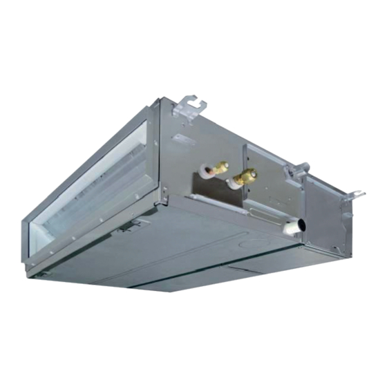
< Concealed Duct Standard Type >
MMD-UP0071BHP-UL
MMD-UP0091BHP-UL
MMD-UP0121BHP-UL
MMD-UP0151BHP-UL
MMD-UP0181BHP-UL
MMD-UP0211BHP-UL
MMD-UP0241BHP-UL
MMD-UP0301BHP-UL
MMD-UP0361BHP-UL
MMD-UP0421BHP-UL
MMD-UP0481BHP-UL
MMD-UP0541BHP-UL
R410A
January, 2023
Advertisement
Table of Contents
Troubleshooting

Related Manuals for Carrier TOSHIBA MMD-UP0071BHP-UL


Summary of Contents for Carrier TOSHIBA MMD-UP0071BHP-UL
- Page 1 FILE NO. SVM-22078 SERVICE MANUAL AIR-CONDITIONER MULTI TYPE INDOOR UNIT < Concealed Duct Standard Type > MMD-UP0071BHP-UL MMD-UP0091BHP-UL MMD-UP0121BHP-UL MMD-UP0151BHP-UL MMD-UP0181BHP-UL MMD-UP0211BHP-UL MMD-UP0241BHP-UL MMD-UP0301BHP-UL MMD-UP0361BHP-UL MMD-UP0421BHP-UL MMD-UP0481BHP-UL MMD-UP0541BHP-UL R410A January, 2023...
-
Page 2: Table Of Contents
Original instruction Adoption of R410A Refrigerant This Air Conditioner is a new type which adopts a refrigerant R410A an environmentally friendly refrigerant. CONTENTS PRECAUTIONS FOR SAFETY ................1. SPECIFICATIONS ....................2. AIR DUCTING WORK..................... 3. DIMENSIONAL DRAWING..................4. WIRING DIAGRAMS ....................5. - Page 3 • The qualified service person is a person who installs, repairs, maintains, relocates and removes the air conditioners made by Toshiba Carrier Corporation. He or she has been trained to install, repair, maintain, relocate and remove the air conditioners made by Toshiba Carrier Corporation...
- Page 4 Definition of Protective Gear When the air conditioner is to be transported, installed, maintained, repaired or removed, wear protective gloves and ‘safety’ work clothing. In addition to such normal protective gear, wear the protective gear described below when undertaking the special work detailed in the table below.
- Page 5 Warning Indications on the Air Conditioner Unit [Confirmation of warning label on the main unit] Confirm that labels are indicated on the specified positions If removing the label during parts replace, stick it as the original. Warning indication Description WARNING WARNING ELECTRICAL SHOCK HAZARD ELECTRICAL SHOCK HAZARD...
-
Page 6: Precautions For Safety
PRECAUTIONS FOR SAFETY The manufacturer shall not assume any liability for the damage caused by not observing the description of this manual. DANGER Before carrying out the installation, maintenance, repair or removal work, be sure to set the circuit breaker for both the indoor and outdoor units to the OFF position. Otherwise, electric shocks may result. - Page 7 WARNING Before starting to repair the air conditioner, read carefully through the Service Manual, and repair the air conditioner by following its instructions. Only qualified service person is allowed to repair the air conditioner. Repair of the air conditioner by unqualified person may give rise to a fire, electric shocks, injury, water leaks and / or other problems.
- Page 8 Do not modify the products. Do not also disassemble or modify the parts. It may cause a fire, electric shock or injury. Prohibition of modification. When any of the electrical parts are to be replaced, ensure that the replacement parts satisfy the specifications given in the Service Manual (or use the parts contained on the parts list in the Service Manual).
- Page 9 After repair work, surely assemble the disassembled parts, and connect and lead the removed wires as before. Perform the work so that the cabinet or panel does not catch the inner wires. If incorrect assembly or incorrect wire connection was done, a disaster such as a leak or fire is caused Assembly / at user’s side.
- Page 10 When the service panel of the outdoor unit is to be opened in order for the compressor or the area around this part to be repaired immediately after the air conditioner has been shut down, set the circuit breaker to the OFF position, and then wait at least 10 minutes before opening the service panel. If you fail to heed this warning, you will run the risk of burning yourself because the compressor pipes and other parts will be very hot to the touch.
- Page 11 • Refrigerant R410A This air conditioner adopts a type refrigerant R410A which does not deplete the ozone layer. 1. Safety Caution Concerned to R410A Refrigerant Accompanied with change of refrigerant, the refrigerating oil has been also changed. Therefore, be sure that water, dust, the former refrigerant or the former refrigerating oil is not mixed into the refrigerating cycle of the air conditioner with new refrigerant during installation work or service work.
- Page 12 4. Tools (1) Required Tools for R410A Mixing of different types of oil may cause a trouble such as generation of sludge, clogging of capillary, etc. Accordingly, the tools to be used are classified into the following three types. 1) Tools exclusive for R410A 2) Tools exclusive for R410A, but can be also used for conventional refrigerant 3) Tools commonly used for R410A and for conventional refrigerant The table below shows the tools exclusive for R410A and their interchangeability.
-
Page 13: Specifications
1. SPECIFICATIONS Concealed Duct type MMD-UP0071BHP-UL MMD-UP0091BHP-UL Model name 7.50 9.50 Cooling Capacity (KBtu/h) 8.50 10.5 Heating Capacity (KBtu/h) 1Ph. 208/230V ~ 60Hz Power supply Running current 0.45 0.58 Electrical characteristics Power consumption (kW) 0.070 0.090 Starting current 0.65 0.78 Main unit Zinc hot dipping steel plate Appearance... - Page 14 Concealed Duct type Model name MMD-UP0121BHP-UL MMD-UP0151BHP-UL MMD-UP0181BHP-UL MMD-UP0211BHP-UL 15.4 18.0 21.0 (KBtu/h) 12.0 Cooling Capacity 17.0 20.0 24.0 (KBtu/h) 13.5 Heating Capacity 1Ph. 208/230V ~ 60Hz Power supply Running current 0.83 0.83 0.90 1.25 Electrical characteristics Power consumption 0.130 0.140 0.210 (kW)
- Page 15 Concealed Duct type Model name MMD-UP0241BHP-UL MMD-UP0301BHP-UL MMD-UP0361BHP-UL 24.0 30.0 36.0 (KBtu/h) Cooling Capacity (KBtu/h) 27.0 34.0 40.0 Heating Capacity 1Ph. 208/230V ~ 60Hz Power supply 1.97 Running current 1.25 1.31 Electrical characteristics Power consumption (kW) 0.210 0.220 0.330 Starting current 2.05 2.11 2.77...
- Page 16 Concealed Duct type MMD-UP0421BHP-UL MMD-UP0481BHP-UL MMD-UP0541BHP-UL Model name 42.0 48.0 54.0 (KBtu/h) Cooling Capacity 47.5 54.0 60.0 (KBtu/h) Heating Capacity 1Ph. 208/230V ~ 60Hz Power supply 1.97 Running current 2.03 2.03 Electrical characteristics Power consumption 0.330 0.340 0.340 (kW) Starting current 2.77 2.83 2.83...
-
Page 17: Air Ducting Work
2. AIR DUCTING WORK Static pressure characteristics UP0071 type UP0091type Standard air flow: 320 CFM Standard air flow: 395 CFM 0.80 0.70 0.60 0.6 in.WG- High tap 0.50 0.6 in.WG- High tap 0.4 in.WG- Mid 0.40 0.4 in.WG- Mid tap 0.30 0.4 in.WG- Low tap 0.4 in.WG-Low tap... - Page 18 UP0361, UP0421 type UP0481, UP0541 type Standard air flow: 1130 CFM Standard air flow: 1175 CFM 0.8 in.WG- H 0.8 in.WG- High tap 0.6 in.WG- Mid tap 0.6 in.WG- Mid tap 0.6 in.WG- High tap 0.6 in.WG- High tap 0.6 in.WG- Low tap 0.6 in.WG- Low tap 0.4 in.WG- High tap 0.4 in.WG-...
-
Page 19: Dimensional Drawing
3. DIMENSIONAL DRAWING Unit : in (mm) Hanging bolt pitch B 0.9"(22) 29.5"(750) Main unit dimension A 2.0"(50) Hanging bolt pitch 25.6"(650) 2.0"(50) External dimensions of flange C 13.6"(345) 7.4" (187.5) 14.0"(355) 1.0"(25) Access panel 16.3"(415) Electrical Drain pan / Drain control box 22.4"(570) pump check cover... - Page 20 UP0071, UP0091 UP0121, UP0151, UP0181 <Bottom air intake> <Bottom air intake> 37.8" 26.0" (959.4) (659.4) 1.5" 3.9" 3.9" 3.9" 3.9" 3.9" 3.9" 3.9" 3.9" 3.9" 1.5" 1.5" 3.9" 3.9" 3.9" 3.9" 3.9" 3.9" 1.5" (37.5) (100) (100) (100) (100) (100) (100) (100) (100)
-
Page 21: Wiring Diagrams
4. WIRING DIAGRAMS 1 2 3 4 5 - 21 -... -
Page 22: Parts Rating
5. PARTS RATING 0071BHP-UL 0091BHP-UL 0121BHP-UL 0151BHP-UL 0181BHP-UL Model MMD-UP ICF-340W150-2A ICF-340W150-1A Fan motor PMD-08D12TF-2 Drain pump motor Float switch FS-1A-31-3 PAM-MD12TF-301 Pulse motor valve 12.9" (328 mm) TA sensor Ø0.16"(4mm), 39.4" (1000mm) TC1 sensor Ø0.24"(6mm), 39.4" (1000mm) TC2 sensor Ø0.24"(6mm), 39.4"... -
Page 23: Refrigerant Cycle Diagram
6. REFRIGERANT CYCLE DIAGRAM Indoor unit Liquid side Gas side Strainer Capillary tube Heat exchanger Pulse Motor Valve (PMV) Distributor Sensor (TCJ) Sensor (TC2) Sensor (TC1) Sensor Fan motor (TA) Explanation of functional parts in indoor unit Functional part name Functional outline Pulse Motor Valve (Connector CN82 (6P): Blue) -
Page 24: Control Outline
7. CONTROL OUTLINE Indoor unit Control specifications Item Specification outline Remarks Upon power 1. Identification of outdoor unit supply reset When the power supply is reset, the outdoor unit is identified, and control is redirected according to the identification result. 2. - Page 25 Item Specification outline Remarks Fan speed 1. The fan operates in one of the four speed modes of “HIGH (HH)”, “MED HH > H+ > H > (H)”, “LOW (L)” and “AUTO” on the basis of a command issued via the L+ >...
- Page 26 Item Specification outline Remarks Cold air 1. In heating operation, the upper limit of the fan tap is set according to the TCJ: Indoor heat discharge lower of whichever is the higher between TC2 sensor and TCJ sensor exchanger prevention temperatures, on the one hand, and TC1 sensor temperature, on the sensor control...
- Page 27 Item Specification outline Remarks • Recovery operation Cooling oil While the outdoor unit is recovering cooling oil (refrigerant), the indoor normally takes (refrigerant) units perform the following control tasks: place roughly every recovery control [common for operational (cooling thermo ON / thermo OFF / FAN), as 2 hours.
- Page 28 Item Specification outline Remarks Filter sign 1. The indoor fan’s cumulative hours of operation are counted, and when “FILTER ” displayed display these exceed the prescribed value (2500H), a filter replacement signal (not applicable is sent to the remote controller to display a filter sign on it. to wireless type) 2.
- Page 29 Item Specification outline Remarks DC motor 1) When the fan operation has started, positioning of the stator and the Check code “P12” rotor are performed. (Moves slightly with tap sound) 2) The motor operates according to the command from the indoor controller.
- Page 30 Item Outline of specifications Remarks Secondary Secondary heating can be used while heating operations are performed. heating <Control Outline (Normal Mode)> 1) If the difference between the indoor temperature and the outdoor temperature is large while the air conditioner is operating, turn ON the secondary heating.
- Page 31 Item Outline of specifications Remarks Secondary DN [C5] Data Secondary heating mode heating (Continued) 0000 Normal mode (Factory default) 0001 Flip mode : Set temp. out (high) [ºF(ºC)] DN [C6] Data "-0015": 5ºF(-15ºC) to "0015": 59ºF(15ºC) -0015 "0000": 32ºF(0ºC) (Factory default) 0015 [ºF(ºC)] DN [C7]...
-
Page 32: Communication Type, Model Names And The Maximum Number Of Connectable Units
8. COMMUNICATION TYPE, MODEL NAMES AND THE MAXIMUM NUMBER OF CONNECTABLE UNITS 8-1. This air conditioning (U series) has new communication specifications, and TU2C- Link (U series) and TCC-Link (other than U series) differ in a communication type. For the communication type and the model names such as each unit or remote controllers, refer to the following table. -
Page 33: Applied Control And Functions (Including Circuit Configuration)
9. APPLIED CONTROL AND FUNCTIONS (INCLUDING CIRCUIT CONFIGURATION) 9-1. Indoor Controller Block Diagram (MCC-1720) 9-1-1. In case of connection of wired remote controller. Wired header remote controller (Up to 2 units) Schedule timer (weekly timer mode.) Display LCD Function setup Display LCD LCD driver Display LED... -
Page 34: In Case Of Connection Of Wireless Remote Controller
9-1-2. In case of connection of wireless remote controller. Display Operation Indoor unit #1 (Heder) (Follower) (Follower) Indoor control P.C. board (MCC-1720) EEPROM2 DC20V Remote controller EEPROM1 communication circuit DC5V TA sensor DC12V TC1 sensor Same as left Same as left TC2 sensor Drain Driver... -
Page 35: Controller
9-1-3. In case of connection of wired remote controller and Wireless remote controller. Schedule timer (weekly timer mode.) Wired header remote controller (Up to 2 units) Display LCD Function setup Display LCD LCD driver Display LED Key switch Function setup Key switch DC5V Remote controller... -
Page 36: Indoor Print Circuit Board
9-2. Indoor Print Circuit Board MCC-1720 - 36 -... -
Page 37: Optional Connector Specifications Of Indoor P.c. Board
9-3. Optional connector specifications of indoor P.C. board Function Connector No. Pin No. Specification Remarks Fan output DC12 V Factory default setting: ON when indoor unit in operation and OFF when indoor unit at rest CN32 Output * Fan can be operated on its own by pressing FAN button on remote controller (DN = 31) Start / stop input Start / stop input for HA (J01: In place / Removed =... -
Page 38: Functions At Test Run
9-4. Functions at test run � Cooling/Heating test run check The test run for cooling/heating can be performed from either indoor remote controller or outdoor interface P .C. board. 1. Start/Finish operation of test run � Test run from indoor remote controller Wired remote controller: Refer to the below item of “Test run”... - Page 39 <RBC-AWSU52-UL> In the “Field setting menu” screen, press ] and [ ] to select “Test mode”, and then press [ Set/Fix] Test mode is set, and returns to the “Field setting menu” screen. Press the [ Return] button 2 times, to open screen (2).
-
Page 40: Test Operation Of Indoor Unit
9-5. Test operation of indoor unit Check function for operation of indoor unit (Functions at indoor unit side) This function is provided to check the operation of the indoor unit singly without communication with the remote controller or the outdoor unit. This function can be used regardless of operation or stop of the system. However, if using this function for a long time, a trouble of the equipment may be caused. -
Page 41: Applied Control
10. APPLIED CONTROL 10-1. Setup of Selecting Function in Indoor Unit (Be Sure to Execute Setup by a Wired Remote Controller) <RBC-AMT***> Push the buttons simultaneously and hold for at CODE No. least 4 seconds. SET DATA 00 01 SETTING TEST UNIT No. - Page 42 <RBC-AWSU52-UL> Press [ Menu] to open the “Menu” Press and hold [ Menu] and [ ] at the same time to open “Field setting menu” Press and hold 4 seconds. In the “Field setting menu” screen, press ] and [ ] to select “DN setting”, and then press [ Set/Fix]...
- Page 43 Indoor unit function Code No. (DN Code) table (includes functions needed to perform applied control on site) Description Item At shipment Filter display delay timer 0000: None 0001: 150H Depending on model 0002: 2500H 0003: 5000H type 0004: 10000H t l i f 0001: High degree of dirt (Half of standard time) Central control address 0001: No.1 unit...
- Page 44 Description Item At shipment ° : F ° 0001: °F c i t Depending on model type High-ceiling adjustment (Air flow selection) Timer setting 0000: Available 0001: Unavailable 0000: Available (wired remote controller) (can be performed) (cannot be performed) Dual set point 0000: Unavailable 0002: Available 0000: Unavailable...
- Page 45 Item Description At shipment Notice code 0000: None 0000: None number 01 0001 ~ 0255 : Notice code 0129 : Notice code (201) Notice code 0000: None 0130 : Notice code (202) number 02 (0001 ~ 0255 : TU2C-LINK only) Notice code 0000: None number 03...
- Page 46 Type DN code “10” Value Type Model MMU-UP****HP-UL 4 Way Cassette 0001 MMD-UP****BHP-UL 0004 Concealed Duct Standard *1 Default value stored in EEPROM mounted on service P.C. board Indoor Unit Capacity DN code “11” Value Capacity 0000* Invalid 0001 007 type 0003 009 type 0005...
-
Page 47: Applied Control In Indoor Unit
10- 2. Applied Control in Indoor Unit � Remote location ON/OFF control box (TCB-IFCB-4UL) [Wiring and setup] • Use the exclusive connector for connection with the indoor control P.C. board. • In a group control, the system can operate when connecting with any indoor unit (Control P.C. board) in the group. - Page 48 Ventilating fan control from remote controller [Function] • The start / stop operation can be operated from the wired remote controller when air to air heat exchanger or ventilating fan is installed in the system. • The fan can be operated even if the indoor unit is not operating. •...
- Page 49 <RBC-AWSU52-UL> Press [ Menu] to open the “Menu” Press and hold [ Menu] and [ ] at the same time to open “Field setting menu” Press and hold 4 seconds. In the “Field setting menu” screen, press [ ] and [ ] to select “DN setting”, and then press [ Set/Fix] Press [...
- Page 50 Auto-off feature control [Function] • This function controls the indoor units individually. It is used when the start operation from outside is unnecessary but the stop operation is necessary. • A card switch box or card lock helps protect customers from forgetting to turn off the indoor unit. (not including the following Card Input 3) •...
- Page 51 [Control items] External contact terminal Function Close (Status that card is inserted) Open (Status that card is taken out) Manual prohibition release Manual prohibition Card Input 1 (Manual operation) (Operation stop) Manual prohibition release Manual prohibition Card Input 2 (Automatic operation) (Operation stop) Operation status continues Operation status continues and setting temperature...
- Page 52 [The example of Card Input 5 setting] Code No. (DN) setting External contact terminal Case. [16A] [16b] [16C] [16d] [16F] [170] [171] [172] [173] Close (Status that card is inserted) Open (Status that card is taken n out) data data data data data...
- Page 53 Notice code signal Notice code is a function dedicated to TU2C-Link communication. See service manual for u series outdoor unit for details of Notice code. [Function] • Notice Code is issued if there is signal input to connector of outdoor unit P.C. board. This can be used in cases such as when confirming state of outdoor unit (filter clogging, etc.) by air conditioner system.
- Page 54 Manual address setting using the remote controller Procedure when setting indoor units’ addresses first under the condition that indoor wiring has been completed and outdoor wiring has not been started (manual setting using the remote controller) Wiring example of 2 refrigerant lines Refrigerant line 1 Refrigerant line 2 Outdoor...
- Page 55 <Indoor unit address> 13 13 13 13 13 Push the TEMP. buttons repeatedly to set the CODE No. to Push the TIME buttons repeatedly to set an indoor unit address. Push the button. (It is OK if the display turns on.) <Group address>...
- Page 56 <Indoor unit address> ] to set the item code No. to 13. ] to black highlight the item code (DN), and then press [ ] and [ Press [ ] to set the data indoor unit address. Press [ ] to black highlight the data, and then press [ ] and [ After finishing setting the data of the item code (DN), press [ Set/Fix]...
- Page 57 To find an indoor unit’s position from its address Procedure to know the position of indoor unit body by address while indoor unit No. is known. • Confirm each indoor unit address while indoor unit is stopped. (Be sure to stop air conditioner.) <RBC-AMT >...
- Page 58 <RBC-AWSU52-UL> [Procedure] The position of indoor unit body by address Push the [ MENU] button to display the menu screen. Push and hold the [ MENU] button and the [ ] button at the same time to display the “Field setting menu”. →...
- Page 59 Check code clearing function How to clear the check code using the wired remote controller <RBC-AMT > Clearing a check code of the outdoor unit Clear the currently detected outdoor unit for each refrigerant line to which the indoor unit controlled by the remote controller is connected.
- Page 60 <RBC-AW5U52-UL> Displays the last 10 check codes, and at which unit and when they occurred. In the “Field setting menu” screen, press ] and [ ] to select “Alarm history”, and then press [ Set/Fix] NOTE • The check code history data shows a history of 10 occurrences. If the occurrences exceed 10, the oldest data is deleted. •...
- Page 61 Monitoring function of wired remote controller <RBC-AMT > TEMP. ON / OFF TIMER SET MODE TIME SAVE VENT FILTER RESET TEST SWING/FIX UNIT LOUVER Content Enter the service monitoring mode using the remote controller to check the sensor temperature or operation status of the remote controller, indoor unit, and outdoor unit.
- Page 62 <RBC-AWSU52-UL> Displays the codes and data indicating the operating condition and temperature of each sensor on the indoor units, outdoor units, and remote controllers. In the “Field setting menu screen, press ” ] and [ ] to select “Monitor function ”...
-
Page 63: Troubleshooting
11. TROUBLESHOOTING 11-1. Overview (1) Before engaging in troubleshooting (a) Applicable models All Super Modular Multi System (SMMS- ) models. (Indoor units: MM -UP , Outdoor units: MMY-M P (b) Tools and measuring devices required • Screwdrivers (Philips, flat head), spanners, long-nose pliers, nipper, pin to push reset switch, etc. •... -
Page 64: Troubleshooting Method
11-2. Troubleshooting method The remote controllers (main remote controller and central control device) and the interface P.C. board of an outdoor unit are provided with an a 7-segment display (outdoor interface P.C. board) to display operational status. Using this self-diagnosis feature, the trouble site / trouble part may be identified in the event of a trouble by following the method described below. - Page 65 (Check code detected by remote controller) Check code Display of receiving unit Outdoor 7-segment display Indicator light block Typical trouble site Description of trouble Remote control Operation Timer Ready Sub-code Flash No master remote control, Signals cannot be received from indoor unit; –...
- Page 66 List of Check Codes (Outdoor Unit) (Check code detected by outdoor interface - typical examples) If "HELLO" is displayed on the oudoor 7-segment for 1 minute or more, turn off the power supply once and then turn on the power supply again after passage of 30 seconds or more. When the same symptom appears, it is considered there is a possibility of I/F board trouble.
- Page 67 Check code Display of receiving unit Outdoor 7-segment display Central Indicator light block control or main Typical problem site Description of problem remote Operation Timer Ready Sub-code Flash controller display Outdoor suction 01: TS1 sensor Outdoor suction temperature sensor temperature sensor 03: TS3 sensor (TS1,TS3) has been open/short-circuited.
- Page 68 Check code Display of receiving unit Outdoor 7-segment display Central Indicator light block Typical problem site Description of problem control or main remote Operation Timer Ready Sub-code Flash controller display P.C.board P.C.board Compressor Fan Motor Compressor Fan Motor Trouble in number of There are insufficient number of P.C.
- Page 69 (Check code detected by Inverter of Compressor featuring in outdoor unit - typical examples) Check code Display of receiving unit Outdoor 7-segment display Central Indicator light block Typical problem site Description of proplem control or main remote Operation Timer Ready Sub-code controller Flash...
-
Page 70: Troubleshooting By Check Display On Remote Controller
11-3. Troubleshooting by check Display on Remote Controller <RBC-AMT > (1) Checking and testing When a trouble occurs to an air conditioner, a check code and indoor unit No. are displayed on the display window of the remote controller. Check codes are only displayed while the air conditioner is in operation. - Page 71 <RBC-AWSU52-UL> Check code When an error occurs in the air conditioner, the check Indoor unit number code and the indoor unit number flash on the display of the remote controller. * The check code is only displayed during the operation. When the check code and indoor unit number are displayed, pressing [ Return] opens the “Check”...
- Page 72 Using indoor unit indicators (receiving unit light block) (wireless type) To identify the check code, check the 7-segment display on the header unit. To check for check codes not displayed on the 7-segment display, consult the “List of Check Codes (Indoor Unit)” in “10-2. Troubleshooting method”. : Blinking (0.5 seconds) : Lighting : Goes off...
- Page 73 Cause of trouble Light block Check code Heat exchanger temperature sensor (TCJ) trouble Operation Timer Ready Heat exchanger temperature sensor (TC2) trouble Indoor unit temperature Heat exchanger temperature sensor (TC1) trouble sensor trouble Ambient temperature sensor (TA) trouble Alternate blinking Discharge temperature sensor (TF) trouble Discharge temperature sensor (TD1) trouble Discharge Operation Timer...
- Page 74 Cause of trouble Light block Check code Operation Timer Ready Occupancy sensor trouble Outdoor EEPROM trouble Synchronized blinking Other (indications not involving check code) Cause of trouble Light block Check code Operation Timer Ready – Test run in progress Synchronized blinking Operation Timer Ready Setting incompatibility...
-
Page 75: (7-Segment Display On I/F Board) And Locations To Be Checked
11-4. Check Codes Displayed on Remote Controller and SMMS series Outdoor Unit (7-Segment Display on I/F Board) and Locations to Be Checked) For other types of outdoor units, refer to their own service manuals. Check code Location Check code detection Main Outdoor 7-segment display Description... - Page 76 Check code Location Check code detection Main Outdoor 7-segment display Description System status Check items (locations) condition(s) remote Check detection Sub-code controller code No. of indoor Indoor unit Indoor-outdoor All stop Condition 1 • Check power supply to units from communication One indoor unit or more indoor unit.
- Page 77 Check code Location Check code detection Main Outdoor 7-segment display Description System status Check items (locations) condition(s) remote Check detection Sub-code controller code Too many All stop • Combined capacity of • Check capacities of indoor Capacity over indoor units indoor units is too large.
- Page 78 Check code Location Check code detection Main Outdoor 7-segment display Description System status Check items (locations) condition(s) remote Check detection Sub-code controller code Detected Outdoor All stop Outdoor header unit • Check check code outdoor unit No. follower unit receives trouble code from displayed on outdoor trouble outdoor follower unit.
- Page 79 Check code Location Check code detection Main Outdoor 7-segment display Description System status Check items (locations) condition(s) remote Check detection Sub-code controller code TD2 sensor All stop Sensor resistance is infinity • Check connection of TD2 trouble or zero (open/short circuit). sensor connector.
- Page 80 Check code Location Check code detection Main Outdoor 7-segment display Description System status Check items (locations) condition(s) remote Check detection Sub-code controller code Outdoor All stop Readings of high-pressure • Check connection of high- pressure Pd sensor and low-pressure pressure Pd sensor sensor wiring Ps sensor are switched.
- Page 81 Check code Location Check code detection Main Outdoor 7-segment display Description System status Check items (locations) condition(s) remote Check detection Sub-code controller code TD1 sensor All stop Discharge temperature of • Check installation of TD1 miswiring compressor 1 (TD1) does sensor.
- Page 82 Check code Location Check code detection Main Outdoor 7-segment display Description System status Check items (locations) condition(s) remote Check detection Sub-code controller code 01: TK1 oil Oil level All stop No temperature change is • Check for disconnection of circuit trouble detection detected by TK1 despite TK1 sensor.
- Page 83 Check code Location Check code detection Main Outdoor 7-segment display Description System status Check items (locations) condition(s) remote Check detection Sub-code controller code Outdoor All stop Initial setting of I/F P.C. • Check model setting of — capacity not set board has not been P.C.
- Page 84 Check code Location Check code detection Main Outdoor 7-segment display Description System status Check items (locations) condition(s) remote Check detection Sub-code controller code 1∗: Compressor Activation of All stop High-pressure SW is • Check connection of high- 1 side high-pressure activated.
- Page 85 Check code Location Check code detection Main Outdoor 7-segment display Description System status Check items (locations) condition(s) remote Check detection Sub-code controller code Detected indoor Indoor unit Indoor overflow All stop • Float switch operates. • Check float switch address trouble •...
- Page 86 Check code Location Check code detection Main Outdoor 7-segment display Description System status Check items (locations) condition(s) remote Check detection Sub-code controller code Discharge All stop Discharge temperature • Check outdoor service temperature (TD2) exceeds 115 ˚C. valves (gas side, liquid TD2 trouble side) to confirm full opening.
- Page 87 Check code Location Check code detection Main Outdoor 7-segment display Description System status Check items (locations) condition(s) remote Check detection Sub-code controller code 1∗: Fan P.C. Fan INV. Outdoor fan All stop Protected operation of Fan • Check fan motor. board 1 P.C.
- Page 88 Check codes Displayed on by Central Control Device Check code Location Check code detection Main Outdoor 7-segment display Description System status Check items (locations) condition(s) remote Check detection Sub-code controller code Indoor unit Indoor-remote Stop of There is no communication •...
- Page 89 Points to Note When Servicing Compressor (1) When checking the outputs of inverters, remove the wiring from all the compressors. How to Check Inverter Output (1) Turn off the power supply. (2) Remove compressor leads from the compressor P.C. board. (The model with two compressor should remove the wiring for two sets (6 leads).
-
Page 90: Diagnostic Procedure For Each Check Code (Indoor Unit)
11-5. Diagnostic Procedure for Each Check Code (Indoor Unit) - 90 -... - Page 91 - 91 -...
- Page 92 - 92 -...
- Page 93 - 93 -...
- Page 94 - 94 -...
- Page 95 - 95 -...
- Page 96 - 96 -...
- Page 97 - 97 -...
- Page 98 Part name Checking procedure Concealed Duct type Measure the resistance value of each winding by using the tester. Fan motor ICF-340W150-2A ICF-340W150-1A, 2A MMD-UP0071BHP-UL UP0091BHP-UL Position Resistance value 14.8 ± 1.5 Ω Black–Red ICF-340W150-1A MMD-UP0121BHP-UL 14.8 ± 1.5 Ω Black–White UP0151BHP-UL Fan motor inside wiring diagram 14.8 ±...
-
Page 99: Sensor Characteristics
11-6. Sensor characteristics Indoor unit Temperature sensor characteristics Indoor TA sensor Temperature Resistance [˚F (˚C)] [kΩ] Resistance 32 (0) 33.9 [kΩ] 41 (5) 26.1 50 (10) 20.3 59 (15) 15.9 68 (20) 12.6 77 (25) 10.0 86 (30) 95 (35) 104 (40) 113 (45) 122 (50) -
Page 100: Replacement Of P.c.board For Indoor Unit Serviceing
12. REPLACEMENT OF SERVICE P.C. BOARD Indoor Unit CAUTION <Note: when replacing the P.C. board for indoor unit servicing> The nonvolatile memory (hereafter called EEPROM, IC503) on the indoor unit P.C. board before replacement includes the model specific type information and capacity codes as the factory-set value and the important setting data which have been automatically or manually set when the indoor unit is installed, such as system/ indoor/group addresses, high ceiling select setting, etc. - Page 101 [1] Setting data read out from EEPROM (Stop the operation of the unit.) <RBC-AMT > [1] Setting data read out from EEPROM The setting data modified on the site, other than factory-set value, stored in the EEPROM shall be read out. Step 1 Push button on the remote controller simultaneously for more than 4 seconds.
- Page 102 <RBC-AWSU52-UL> Push the [ MENU] button to display the menu screen. Push and hold the [ MENU] button and the ] button at the same time to display the “Field setting menu”. • Push and hold the buttons for more than 4 seconds. Push the [ ] / [ ] button to select...
- Page 103 CODE No. required at least 1. The CODE No. for the Indoor unit type and Indoor unit capacity are Contents required to set the rotation number setting of the fan. 0010 Type 2. If the system/indoor/group addresses are different from those 0011 Indoor unit capacity before replacement, the auto-address setting mode starts and the...
- Page 104 [3] Writing the setting data to EEPROM (Stop the operation of the unit.) <RBC-AMT > Step 1 Push buttons on the remote controller simultaneously for more than 4 seconds. * In the group control operation, the unit No. displayed for the first time is the header unit No.. At this time, the CODE No.
- Page 105 <RBC-AWSU52-UL> Push the [ Menu] button to display the menu screen. Push and hold the [ Menu] button and the [ ] button at the same time to display the “Field setting menu”. • Push and hold the buttons for more than 4 seconds. ] / [ Push the [ ] button to select “7.
- Page 106 Change “Code (DN)” to [0002] with the [ ] / [ ] button. (Filter pollution level) Perform the operation of . Check the other “Code (DN)” also, change “Data” into the setting data written down in [1] Setting data read out from EEPROM if the setting data is different. Return] button.
- Page 107 Table 1.Setting data(CODE No. table(example)) Item Setting data Factory-set value Filter display delay timer 0002 : 2500H Dirty state of filter 0000 : Standard Central control address 00Un/0099 : Unfixed Specific indoor unit priority 0000 : No priority +3.6°F( Heating suction temperature shift Automatic mode 0001 : No automatic Cooling only...
-
Page 108: Detachments
13. DETACHMENTS WARNING CAUTION Be sure to stop operation of the air conditioner before Be sure to put on gloves during working time; work and then turn off switch of the breaker. otherwise an injury will be caused by a part, etc. NOTE In a section, Detachments, the models are expressed as follows for convenience. - Page 109 Part name Procedure Remarks Suction panel 1. Detachment 1) Remove the fixing screws A which fix the suction panel. Loosen the fixing screws B. 2) Slide the suction panel to the arrow side and then remove the panel. 2. Attachment 1) Hook the suction panel to the fixing screws B and tighten screws.
- Page 110 Part name Procedure Remarks Electric parts 1. Detachment 1) Perform works of 1 of (In case of under air intake) Perform works of 1 of (In case of back air intake) Perform works of 1 of 2) Remove the indoor/outdoor connecting wire and remote controller wire from each terminal block.
- Page 111 Part name Procedure Remarks Fan motor, 1. Detachment Fan, 1) Perform works until opening of the electric parts box cover in works of 1 of Fan case 2) Remove connectors for fan motor wiring from control P.C. board. CN333 : Motor power supply (5P: White) CN334 : Motor control (5P: White) 3) Open the fan case (under) and remove it while pressing claws of the fan case...
- Page 112 Part name Procedure Remarks Drain pan 1. Detachment 1) Remove the drain cap and then extract the Bottom base drain water accumulated in the drain pan. NOTE Do not hold the When removing the drain cap, be sure to drain socket. receive drain water using a bucket, etc.
- Page 113 Part name Procedure Remarks Heat 1. Detachment : Screw position exchanger 1) Recover the refrigerant gas and then remove the refrigerant pipe of the indoor UP0071 Type unit. Heat exchanger End plate 2) Perform works of 1 of fixed plate 3) Pull out TC sensor and TCJ sensor wirings from the holder.
-
Page 114: Exploded Views And Parts List
14. EXPLODED VIEWS AND PARTS LIST 14-1. Concealed duct type MMD-UP0071BHP-UL, MMD-UP0091BHP-UL - 114 -... - Page 115 Model name MMU-UP****BHP-UL Location Part No. Description 0071 0091 43T39356 FLANGE 43T44709 REFRIGERATION CYCLE ASSY 43T70319 ASM-HOSE-DRAIN 43T77303 PUMP ASSY 43T51312 SWITCH, FLOAT 43T22337 CASE, FAN, UPPER 43T22335 CASE, FAN, LOWER 43T20340 FAN, MULTI BLADE 43T39416 BAND-MOTOR-L 43T39415 BAND-MOTOR-R 43T21519 MOTOR,FAN 43T39417 BASE-MOTOR...
- Page 116 MMD-UP0121BHP-UL, MMD-UP0151BHP-UL, MMD-UP0181BHP-UL - 116 -...
- Page 117 Model name MMU-UP****BHP-UL Location Part No. Description 0121 0151 0181 43T39357 FLANGE 43T44711 REFRIGERATION CYCLE ASSY 43T44829 REFRIGERATION CYCLE ASSY 43T70319 ASM-HOSE-DRAIN 43T77303 PUMP ASSY 43T51312 SWITCH, FLOAT 43T22337 CASE, FAN, UPPER 43T22335 CASE, FAN, LOWER 43T20340 FAN, MULTI BLADE 43T39416 BAND-MOTOR-L 43T39415...
- Page 118 MMD-UP0211BHP-UL, MMD-UP0241BHP-UL, MMD-UP0301BHP-UL - 118 -...
- Page 119 Model name MMU-UP****BHP-UL Location Part No. Description 0211 0241 0301 43T39358 FLANGE 43T44712 REFRIGERATION CYCLE ASSY 43T70319 ASM-HOSE-DRAIN 43T77303 PUMP ASSY 43T51312 SWITCH, FLOAT 43T22338 CASE, FAN, UPPER 43T22336 CASE, FAN, LOWER 43T20339 FAN, MULTI BLADE 43T39416 BAND-MOTOR-L 43T39415 BAND-MOTOR-R 43T21511 MOTOR-FAN 43T39418...
- Page 120 MMD-UP0361BHP-UL MMD-UP0421BHP-UL, MMD-UP0481BHP-UL, MMD-UP0541BHP-UL - 120 -...
- Page 121 Model name MMU-UP****BHP-UL Location Part No. Description 0361 0421 0481 0541 43T39358 FLANGE 43T44712 REFRIGERATION CYCLE ASSY 43T70319 ASM-HOSE-DRAIN 43T77303 PUMP ASSY 43T51312 SWITCH, FLOAT 43T22338 CASE, FAN, UPPER 43T22336 CASE, FAN, LOWER 43T20339 FAN, MULTI BLADE 43T39416 BAND-MOTOR-L 43T39415 BAND-MOTOR-R 43T21511 MOTOR-FAN...
- Page 122 14-2. Electric Parts CN104 IC501 IC503 SW501 CN33 RY01 CH-49-Z-T Lot No. R DB01 CN01 Model name MMU-UP****BHP-UL Location Part No. Description 0071 0091 0121 0151 0181 0211 43T50411 TC-SENSOR 43T50387 TC-SENSOR (TC2) 43T58320 REACTOR 43T60435 SERV-TERMINAL 43T60362 TERMINAL 43TN9830 PC BOARD ASSY (MCC-1696) 43TN9869 PC BOARD ASSY (MCC-1720)
- Page 123 144/9 MOO 5, BANGKADI INDUSTRIAL PARK, TIVANON ROAD, TAMBOL BANGKADI, AMPHUR MUANG, PATHUMTHANI 12000, THAILAND.