Table of Contents
Advertisement
Part Numbers: CRLOWAMB033A00 THROUGH CRLOWAMB038A00
CONTENTS
SAFETY CONSIDERATIONS . . . . . . . . . . . . . . . . . . . . . . 1
GENERAL . . . . . . . . . . . . . . . . . . . . . . . . . . . . . . . . . . . . . . 1-3
INSTALLATION . . . . . . . . . . . . . . . . . . . . . . . . . . . . . . . . 3-12
Pre-Installation . . . . . . . . . . . . . . . . . . . . . . . . . . . . . . . . . . . 3
V Control . . . . . . . . . . . . . . . . . . . . 5
®
for Motormaster
Step 3 - Configure Motormaster V Control . . . . . 11
Step 4 - Test Motormaster V Control . . . . . . . . . . . 11
START-UP . . . . . . . . . . . . . . . . . . . . . . . . . . . . . . . . . . . . 11-13
TROUBLESHOOTING. . . . . . . . . . . . . . . . . . . . . . . . . 13-15
SAFETY CONSIDERATIONS
Installation, start-up, and servicing of this equipment can be
hazardous due to system pressures, electrical components, and
equipment location (roofs, elevated structures, etc.).
Only trained, qualified installers and service technicians
should install, start up, and service this equipment.
When working on this equipment, observe precautions in
the literature and on tags, stickers, and labels attached to the
equipment and any other safety precautions that may apply.
48/50P2,P3,P4,P5 UNIT SIZE
035
030, 040-060
070
075-100
Manufacturer reserves the right to discontinue, or change at any time, specifications or designs without notice and without incurring obligations.
Catalog No. 04-53480070-01
Installation Instructions
Page
Table 1 - Replacement Motor Part Numbers
VOLTAGE
208/230-3-60
400-3-50, 460-3-60
575-3-60
380-3-60
208/230-3-60
400-3-50, 460-3-60
575-3-60
380-3-60
208/230-3-60
400-3-50, 460-3-60
575-3-60
380-3-60
208/230-3-60
400-3-50, 460-3-60
575-3-60
380-3-60
Printed in U.S.A.
48/50P2,P3,P4,P5030-100
Low Ambient Operation
MOTORMASTER
Open all remote disconnects before servicing this equip-
ment. Electrical shock could result in personal injury.
This book contains instructions for the installation, start-up,
and service of the Motormaster V (MMV) control on
48/50P030-100 units.
The Motormaster V control is a motor speed control device
which adjusts condenser fan motor speed in response to varying
liquid refrigerant pressure. A properly applied Motormaster V
control extends the operating range of air-conditioning systems
and permits operation at lower outdoor ambient temperatures.
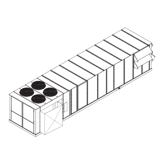
To operate these units at very low ambient temperatures, Mo-
tormaster V controls (Fig. 1) must be added. Field-fabricated and
installed wind baffles are also required for units in areas with pre-
vailing winds of more than 5 mph (8 kph) and where tempera-
tures drop below 32 F (0° C). The Motormaster V control permits
operation of the unit to an ambient temperature of -20 F (-29 C).
The control regulates the speed of one or two 3-phase fan motors
depending on unit size. Replacement of the fan motor on most
units is not necessary since the control is compatible with the
factory-installed fan motors. To verify that unit fan motors are
compatible with the control see Table 1.
See Tables 2-4 for the Motormaster V control accessory pack-
age usage and contents. Field wiring of control is required.
Form 48/50P-2SI
®
V Control Accessory
50/60 Hz
WARNING
GENERAL
ACCESSORY PART NUMBER
Not Required, Std Unit Motor
Not Required, Std Unit Motor
Not Required, Std Unit Motor
HD56AK380
HD52AK002
HD52AK002
Not Required, Std Unit Motor
Not Required, Std Unit Motor
HD52AK002 (2 Required)
HD52AK002 (2 Required)
Not Required, Std Unit Motor
Not Required, Std Unit Motor
Not Available
HD52AK002 (2 Required)
Not Required, Std Unit Motor
Not Available
Pg 1
9-09
Replaces: New
Advertisement
Table of Contents

Related Manuals for Carrier MOTORMASTER 48/50P3


Summary of Contents for Carrier MOTORMASTER 48/50P3
-
Page 1: Table Of Contents
Installation Instructions Part Numbers: CRLOWAMB033A00 THROUGH CRLOWAMB038A00 CONTENTS SAFETY CONSIDERATIONS ..... . 1 GENERAL ........1-3 INSTALLATION . -
Page 2: Component List
NOTE: Wire colors for MMPT: 2 — BLACK (A) 5 — GREEN (C) 6 — RED (B) PRESSURE TRANSDUCER Table 2 — Motormaster® V Control Package Contents — 48/50P030-060 Units ITEM Connector ( -in.) Connector (1-in.) Controller, 230 V 2 Hp Controller, 460 V 2 Hp Controller, 575 V 2 Hp Enclosure... -
Page 3: Installation
Table 3 — Motormaster V Control Package Contents — 48/50P070-100 Units ITEM Connector ( -in.) Connector (1-in.) Controller, 230 V 2 Hp Controller, 460 V 2 Hp Controller, 575 V 2 Hp Enclosure Enclosure Cover Enclosure Mounting Bracket Fan Relay Relay Base Fuse Block Fuse 15A, KTK-R, Class CC... - Page 4 WIND BAFFLE BAFFLE INSTALLATION LOCATION (SIZES 050 AND 060 SHOWN) a48-8560 Fig. 2 — Wind Baffle Details UNIT SIZE QUANTITY 030,035 Not Used 040-060 78.125 ± 0.125 070-100 Not Used NOTE: 48/50P030, 035, and 070-100 units do not require baffles. a48-8561 DIMENSION “A”...
-
Page 5: Control
Step 2 — Mounting and Electrical Connec- tions for Motormaster® V Control WARNING To avoid possibility of electric shock and personal injury, open and tag all electrical disconnects before installing or servicing unit. WARNING Hazard of electric shock. Wait three minutes after discon- necting incoming power before servicing drive. - Page 6 UNIT FAN ARRANGEMENT 48/50P 030,035 050-060 070,075 090,100 REMOVE PANEL RUN ELECTRICAL HARNESSES UP THE SIDE OF THE UNIT IN THE SPACE BETWEEN THE CORNER POST AND THE CONTROL BOX. ROUTE THE WIRING INTO THE WIRE TRAY, THEN RUN APPROPRIATE WIRES TO OFM 1 AND MOTORMASTER CONTROL Fig.
-
Page 7: Mmv Control Mounting 48/50P040 Units
REMOVE PANEL RUN ELECTRICAL HARNESSES UP THE SIDE OF THE UNIT IN THE SPACE BETWEEN THE CORNER POST AND THE CONTROL BOX, THEN ALONGSIDE THE WIRE TRAY. ROUTE APPROPRIATE WIRES TO MOTORMASTER AND OFM 3 RUN TRANSDUCER HARNESS FROM CIRCUIT A TRANSDUCER TO MOTORMASTER ALONG THE LENGTH OF THE BOTTOM OF THE CONDENSER COIL THEN UP INTO MOTORMASTER. -
Page 8: 48/50P Control Box Details
MMF-A MMF-B a48-8565 OFM-1 (030,035,050-060) OFM-3 (040) GRN/YEL, DRAIN MM-F 22 23 11 12 13 a48-8566 Fig. 8 — Motormaster FR-A FR-B Fig. 7 — 48/50P Control Box Details MMV-A T1 T2 T3 B- B+ ® V Accessory Wiring — 48/50P030-060 Units LEGEND —... - Page 9 f. Run the FR cable through the the MMV enclosure (do not tighten connector screws at this time). Connect black wire to MMV terminal 2 and red wire to MMV terminal 1, 13A, or 13C (see Table 4). Place 1 small varnish cloth 38C24601 around both cables at the point they enter the -in.
- Page 10 b. In main control box connect one Motormaster VFD harness 48ZZ401971 to the load side of MMF-A (label the opposite end of this harness as MMF-A) and the other Motormaster VFD har- nesses 48ZZ401971 to the load side of MMF-B (label the opposite end of this harness as MMF-B).
-
Page 11: Step 2 - Mounting And Electrical Connections Step 3 - Configure Motormaster V Control
ROUTE THROUGH SNAP BUSHING MOTORMASTER A CONTROL MOTORMASTER B CONTROL TRANSDUCER A a48-8568 Fig. 10 — MMV Control Mounting — 48/50P090,100 Units Step 3 — Configure Motormaster The Motormaster V control is configured for propor- trol — tional integral (PI) control mode. The Motormaster V varies the condenser fan motor speedto maintain a set point of 320 psig liquid line pressure in response to a 0 to 5 vdc feed- back signal from the liquid line pressure transducer. - Page 12 OFM-1 (070,075) OFM-2 (090,100) MMF-B 22 23 11 12 13 OFM-3 (070,075) OFM-6 (090,100) MMF-A a48-8569 Fig. 11 — Motormaster CIRCUIT B GRN/YEL, DRAIN MMV-B T1 T2 T3 B- B+ CIRCUIT A GRN/YEL, DRAIN MMV-A T1 T2 T3 B- B+ ®...
-
Page 13: Troubleshooting
Motormaster V control. CAUTION It is strongly recommended that the user NOT change any programming without consulting Carrier service personnel. Unit damage may occur from improper programming. TO ENTER PASSWORD AND CHANGE PROGRAM VALUES: 1. -
Page 14: Program Parameters For Operating Mode
Table 5 — Program Parameters for the Operating Mode PARAMETERS Line Voltage: 01 = low line, 02 = high line Carrier Freq: 01 = 4 kHz, 02 = 6 kHz, 03 = 8 kHz Startup mode: flying restart Stop mode: coast to stop... -
Page 15: Fault Codes
Manual The EPM is missing or damaged. Manual The control board has sensed a problem Manual User data and Carrier defaults in the EPM are corrupted. Automatic Line voltage is too high; Deceleration rate is too fast; Overhauling load. Automatic... - Page 16 Copyright 2009 Carrier Corporation Manufacturer reserves the right to discontinue, or change at any time, specifications or designs without notice and without incurring obligations. Catalog No. 04-53480070-01 Printed in U.S.A. Form 48/50P-2SI Pg 16 9-09 Replaces: New...