Grandstream Networks GSC3570 User Manual
Hd intercom & facility control station
Hide thumbs
Also See for GSC3570:
- User manual (85 pages) ,
- Quick installation manual (26 pages) ,
- Quick installation manual (9 pages)

Related Manuals for Grandstream Networks GSC3570


Summary of Contents for Grandstream Networks GSC3570
- Page 1 Grandstream Networks, Inc. GSC3570 HD Intercom & Facility Control Station User Manual...
-
Page 2: Product Overview
100M network port with PoE, full-duplex 2-way HD audio with advanced AEC, and innovative telephony functionalities. The GSC3570 is fully interoperable with nearly all major SIP platforms on the market and can be seamlessly integrated with Grandstream’s entire range of UC product lines including SIP-based door systems, security cameras, IP PBXs, and video conferencing systems and services. -
Page 3: Getting Started
Micro USB input: 5VDC/2A Operation: -10°C to 50°C, Storage: -20°C to 60°C, Temperature and Humidity Humidity: 10% to 90% Non-condensing Package GSC3570 Intercom Phone, quick installation guide, wall mount bracket. Contents Compliance FCC, CE, RCM, IC Table 2: GSC3570 Technical Specifications GETTING STARTED This chapter provides basic installation instructions including the list of the packaging contents and information for obtaining the best performance with the GSC3570. - Page 4 Figure 1: GSC3570 Package Content Note Check the package before installation. If you find anything missing, contact your system administrator. GSC3570 Wiring Connection The following figure and table below show the Connection PINs available on the GSC3570: Figure 2: GSC3570 Wiring Connection Port Jack...
-
Page 5: On-Wall Mounting
The GSC3570 can be attached to the wall or in-wall using the slots for wall mounting. Figure 3: Built-in Stand and Mounting Slots on The GSC3570. On-Wall Mounting The GSC3570 can be mounted on the wall. Please refer to the following steps for Wall installation:... -
Page 6: In-Wall Mounting
Figure 4: On-wall Mounting In-Wall Mounting Figure 5: In-Wall Mounting Connecting the GSC3570 To set up your GSC3570 from the web interface, please follow the steps below:... - Page 7 To setup your GSC3570 from the LCD, please follow the steps below: 1. Make sure the device is idle. 2. Slide to the second home page and press “Setting”. Browse the GSC3570 MENU for Status, Network information, Features and Basic/Advanced Settings…...
-
Page 8: Connection Examples
Alarm Output 125VAC/0.5A, 30VDC/2A, Normal Open, PINs The Alarm_In circuit, if there is any voltage change between 9V and 15V, as specified in the table above, the GSC3570 Alarm_In port will detect it and trigger the action and event. Higher voltage and wrong polarity connection are prohibited because this will damage the devices. - Page 9 Settings�� External Service. 2. Select the Service Type, it could be GDS, Others, or HTTP in case you want to integrate GSC3570 with 3 party Door Access Control system 3. Select Account on which the remote door opening with softkey will be applied on.
-
Page 10: Door Settings
Figure 13: External Service: LCD Configuration 9. At the GSC3570 idle screen, once configured correctly, there will be one or two virtual buttons displayed at lower left corner of the screen. If one door configured, one button will be displayed; if two doors configured, two buttons will be displayed. - Page 11 This feature requires GSC3570 and GDS3710/GDS3705 paired together to function. With GDS3710 or GDS3705 installed outside, the GSC3570 is installed inside, the strike or lock is wired directly to the Alarm_Out interface of GSC3570 to control the door from inside, therefore more secure compared to the strike wired directly to GDS3710/GDS3705 at outside. Below is...
- Page 12 Using GSC3570 as Doorbell and Door opener The GSC3570 can behave like a doorbell and an open door if the door strikes wired directly to the relay control port of the GSC3570. For licensed electricians, this is a perfect digital upgrade solution for users with a broken traditional analog doorbell system.
- Page 13 Figure 17: GSC3570 as Digital Doorbell and door opener example This feature is designed to allow GSC3570 to function like a traditional doorbell, and open the door if wired to an electric lock, a simple digital upgrade to a traditional (broken) doorbell. If combined with an IP camera, it can help to monitor and update the home security without paying the subscription fee usually involved for such a service.
- Page 14 2. Choose “DO mode”, select “Alarm out” if no door strike connected and only want to use the Ding-Dong doorbell tone. No virtual open door button will be displayed in Alarm Message. 3. Choose “Open door” if COM1, NO1/NC1connected to strike to control door opening. Green virtual open door button when be displayed in Alarm Message when doorbell switch pressed 4.
- Page 15 (if configured and wired the strike). Press the green “Open door” virtual button, the relay will take reaction to open the door. The GSC3570 top right corner will also display a door opened icon and an “alarm”...
- Page 16 If using GSC3570 Relay, ONLY ONE DOOR can be controlled. The PIN and other settings are the same as SIP remote open door or GSC3570 secure open door. The difference will come out at the touch screen UI operation of GSC3570.
- Page 17 GSC3570 Open Door NO SIP Call: This is new feature. At the GSC3570 idle screen, press “Monitor →Door system”, the related GDS37XX will be displayed. In the blue bar, left is a “Phone”icon and right is the “Open door”icon. The“Phone”icon will establish SIP call as previous firmware behaved.
- Page 18 Figure 29: RTSP Audio volume control Screen Snapshot During RTSP Streaming or SIP Video Call This feature does not need any configuration and enabled by default, but SD card is required for this feature to work correctly. RTSP Streaming: During RTSP steaming, in the middle of the screen, a virtual “Snapshot” button will appear. Press that button will capture current screen and the snapshot will be saved in the SD.
- Page 19 Figure 31: SIP Video Call Snapshot The file path will display in the screen then disappear after a while. Press the “File «icon from GSC3570 idle screen, select “videoshot” file folder, the snapshots will be stored based on folder using “date” when snapshot taken. Select related folder will see the snapshots stored.
- Page 20 6. Click on Save and Apply. Figure 36: IPC: Web Configuration LCD configuration: 1. Tap the menu button if GSC is idle state. 2. On the first screen menu, tap Monitor�� IP Camera. 3. Press the Add or + button to add a new IP Camera. 4.
- Page 21 Back button. Note The call can only be hung up from the other party (Caller party) and not from the GSC3570 side when the call is hung up from the other party, the RTSP stream is resumed on the GSC3570.
-
Page 22: Arming Mode
Arming Mode The GSC3570 can be connected to 1 Active Alarm IN and up to 3 Passive Alarm IN inputs. Each detector input is linked to a Zone that can be set with different Alarm Action (instant, delayed, 24h alarm). -
Page 23: Web Interface Configuration
Alarm & SOS Calling The GSC3570 can be configured with a SOS key as when this key is hold the GSC3570 will trigger will be ringing the extension(s) configured under SOS panel from either the web GUI or LCD Menu. - Page 24 Dynamic, so the GSC will use the first available line). 5. Click on Save button. The GSC3570 can be set with trigger button to execute the Alarm output action and numbers configured on Alarm panel on the web interface will be ringing as well.
- Page 25 GSC3570 LCD SETTINGS The GSC3570 LCD MENU provides an easy access to the settings on the GSC3570. Some of the settings from Web GUI could be configured via the LCD as well. The following table shows the LCD menu options.
-
Page 26: Access Lcd Settings
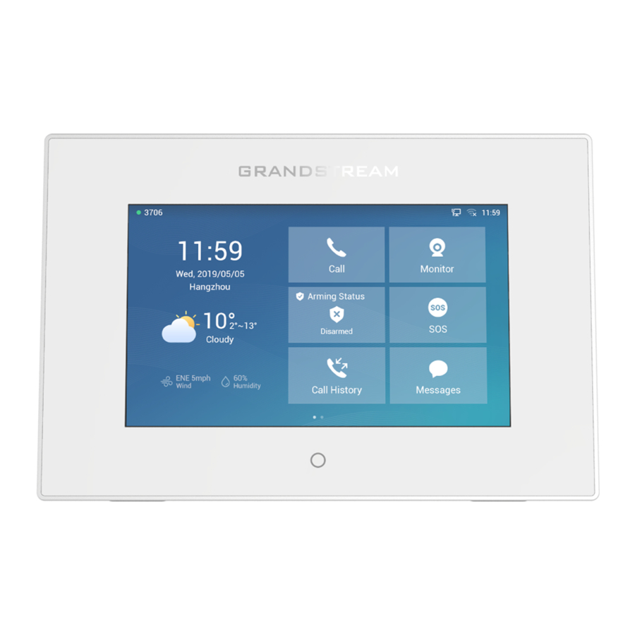
Call, Monitor APP and Settings…etc. In addition to the improved Panel in idle screen (at top right corner) to display detailed information about the GSC3570. For example, from below screenshot, user will know that the GSC3570 is using PoE power on, with SD card inserted for storage, and the FTP server is turned onto receive the alarm snapshot of IP cameras along with indication on the registration status of the SIP Account. - Page 27 Figure 48: Idle home Screen-1 Figure 49: Idle home Screen-2 GSC3570 is registered to SIP server with extension number 8608 FTP server is running with device’s IP and Port 21 SD card available 58.24GB with usage 11.51GB. Device IP is 192.168.11.138.
- Page 28 Figure 50: MENU Configuration To open the settings menu, you should: Tap on Settings app on the screen.
-
Page 29: Network Status
Figure 51: GSC3570 System Settings Status Account Status This page displays all available accounts on the phone with respective status (Configured/Not Configured and Registered/Unregistered). Network Status This page displays Network status including Ipv4/v6 address, subnet mask, gateway, DNS server… System Info This page shows system info including Hardware version, P/N, U-boot version, Kernel version, System version, Certificate version, System up time. -
Page 30: Auto Answer
Wi-Fi Tap on “Wi-Fi” to turn on/off Wi-Fi connection. By default, it is turned off. Add Network. If the Wi-Fi network SSID doesn’t show up in the list, or users would like to set up advanced options for the Wi-Fi network, roll to the end of the Wi-Fi list and select “Add Network”. Then Enter SSID, Security type, password and set up address type (DHCP/Static IP) in the prompt dialog. - Page 31 Door system IP Address: Defines the IP Address of the Door system used. Door Control SIP account: Defines the Account used on the door system side for the GSC3570 Relay Mode Door Control Password: Defines the Account used on the door system side for the GSC3570 Relay Mode Display opendoor icon at desktop: Enables the option to display the open door icon on homescreen , This Open Door Button has a higher priority than the GDS device in Monitor =>...
- Page 32 Enable back LED indicator: Enable/disable the back LED indicator. Language Language: Tap to open the list of available languages. Selected language will be used on GSC3570. By default, it is set to “Auto” to automatically select best matching language from available languages based on GSC3570 location.
- Page 33 Screen lock Password: Defines the Pin code that should consist of a minimum of 6 digits. Desktop Shortcut Settings This option allows users to customize the Home screen by Adding Desktop shortcuts. Press “Add shortcut” button and then select the shortcut type : 1.
-
Page 34: Alarm Settings
Reboot Reboot the GSC3570. Advanced Accounts Set up to 4 SIP accounts. Account Settings page allows to configure SIP settings for each account. Tap on Account# to access the settings, when configured press sign (on the top right corner) to confirm the changes or press back button to cancel them. -
Page 35: Sos Settings
WARNING and ERROR. System log protocol: Select the protocol of syslog (UDP or SSL/TLS). Syslog server address: The URL/IP address for the syslog server. If the GSC3570 has network connection, the phone will send the syslog packets to this server address. -
Page 36: Configuration Via Web Browser
To access the Web GUI: 1. Connect the computer to the same network as the GSC3570. 2. Make sure the GSC3570 is turned on and shows its IP address. You may check the IP from the LCD Menu ��Settings ��Status ��Network Status. - Page 37 If the change is saved only but not applied, after making all the changes, click on the “APPLY” button on top of the page to submit. After submitting the changes in all the Web GUI pages, reboot the GSC3570 to have the changes take effect if necessary (All the options under “Accounts”...
- Page 38 DNS Server 2 The DNS server address 2 obtained on the GSC3570. PPPoE Link PPPoE Link status NAT Type Displays the configured NAT type Display the status of NAT connection for each account on the GSC3570. Traversal Status �� System Info Product Product model of the GSC3570.
- Page 39 This is provided by your VoIP service provider (ITSP). Secondar The URL or IP address, and port of the SIP server. When configured, GSC3570 will register to both Primary and y SIP Secondary SIP Server. If Primary SIP Server is not reachable then the GSC3570 will use Secondary SIP Server for Server GSC3570 services (including making/receiving calls).
-
Page 40: Network Settings
IP x” to send SIP message if at least one of them are not empty. GSC3570 will try to use “Primary IP” first. After 3 tries without any response, it will switch to “Backup IP x”, and then it will switch back to “Primary IP” after 3 re-tries. - Page 41 SIP&SDP messages. The GSC3570 will send empty SDP packet to the SIP server periodically to keep the NAT port open if it is configured to be “Keep-alive”. Configure this to be “No” if an outbound proxy is used. “STUN” cannot be used if the detected NAT is symmetric NAT.
- Page 42 This option is used to control the port information in the Via header and Contact header. If set to No, these l Port in port numbers will use the permanent listening port on the GSC3570. Otherwise, they will use the ephemeral Contact port for the connection.
- Page 43 100rel tag is appended to the value of the required header of the initial signaling messages. The default setting is “No”. When set to “Auto”, the GSC3570 will update the callee ID in the order of P-Asserted Identity Header, Remote- Callee ID Party-ID Header and To Header in the 180 Ringing.
- Page 44 PhonePower and UCM Call center depending on the server type. The default setting is “Standard”. Session Timer Enable This option is used to enable or disable session timer on the GSC3570 side when server side can provide both Session session timer UPDATE or session audit UPDATE. The default setting is “Yes”. Timer The SIP Session Timer extension (in seconds) that enables SIP sessions to be periodically “refreshed”...
- Page 45 To turn off the session timer, select “No”. Timer The default setting is “No”. As a Caller, select UAC to use the GSC3570 as the refresher; or select UAS to use the Callee or proxy server as Specify the refresher. The default setting is “Omit”.
- Page 46 Length Default setting is AES 128&256 bit Crypto Enable or disable the crypto lifetime when using SRTP. If users set to disable this option, GSC3570 will not add Lifetime the crypto lifetime to SRTP header. The default setting is “Yes”.
- Page 47 Jitter Selects either Fixed or Adaptive for jitter buffer type, based on network conditions. The default setting is Buffer “Adaptive”. Type Jitter Buffer Selects jitter buffer length from 100ms to 800ms, based on network conditions. The default setting is “300ms”. Length Configures the number of voice frames transmitted per packet.
- Page 48 This feature enhancement is designed for some ITSP customers that providing video phone call service. Enable Proxy Because GSC3570 does not have camera, this enhancement will improve the video call by sending some fake Video video packets to notify the proxy then displaying black screen on the other side of the video phone.
- Page 49 The default setting is “No”. Rejection Auto If set to “Yes”, the GSC3570 will automatically turn on the speakerphone to answer incoming calls after a short Answer reminding beep. Default setting is “No”. Enables / disables the call waiting feature for the current account. When set to “Default”, global call feature Disable setting will be used.
- Page 50 “Yes” Note: This parameter must be set to “No” for Direct IP Calling to work. Specifies how often the GSC3570 sends a blank UDP packet to the SIP server to keep the “ping hole” Keep-alive Interval on the NAT router to open. The default setting is 20 seconds. The valid range is from 10 to 160.
- Page 51 Order (1-4) Displays the order of the service. When set to “Dynamic”, the GSC3570 will use the first available Account. User can specify from which Account account the call can be made for each destination. Default is Dynamic.
- Page 52 Preferences �� Date and Time Defines the URL or IP address of the NTP server. The GSC3570 may obtain the date and time from NTP Server the server. The default setting is “pool.ntp.org”. Defines the URL or IP address of the NTP server. The GSC3570 may obtain the date and time from Secondary NTP the server.
- Page 53 Time Zone Configures the date/time used on the GSC3570 according to the specified time zone. Allow DHCP Option 2 to Defines whether DHCP Option 2 should override time zone or not. The default setting is “Yes”. Override Time Zone Setting This parameter allows the users to define their own time zone.
- Page 54 Table 8: Settings Page Definitions Network Page Definitions Network �� Basic Settings Allows users to configure the appropriate network settings on the GSC3570 to obtain IPv4 Address IPv4 address. Users could select “DHCP”, “Static IP”. By default, it is set to “DHCP”.
- Page 55 Uploads / deletes 802.1X Client certificate to the GSC3570; or delete existed 802.1X 802.1X Client Certificate Client certificate from the GSC3570. Specifies the HTTP proxy URL for the GSC3570 to send packets to. The proxy server will HTTP Proxy act as an intermediary to route the packets to the destination.
- Page 56 “Enabled”. Maximum Transmission Unit Configure custom MTU. Default is 1500. (MTU) Network �� OpenVPN® Settings OpenVPN® Enable Enable/Disable OpenVPN® feature. Default is No. OpenVPN® Server Address Specify the IP address or FQDN for the OpenVPN® Server. OpenVPN® Port Specify the listening port of the OpenVPN® server. Default is 1194. OpenVPN®...
- Page 57 SNMP Trap IP IP address of the SNMP trap receiver. SNMP Trap Port Port of the SNMP trap receiver (Default 162) SNMP Trap Interval The interval between each trap sent to the trap receiver Community string associated to the trap. It must match the community string of the trap SNMP Trap Community receiver.
- Page 58 and Auto. And set EAP Method, Identity/Password when required. Set up “EAP Method” (Default: None, PEAP, EAP Settings TLS, TTLS, PWD, SIM, AKA or AKA’), “EAP Identity” and “EAP Password” Table 9: Network Page Definitions Maintenance Page Definitions Maintenance �� Web Access User Password Set new password for web GUI access as User.
- Page 59 Allows users to upload the firmware file locally by pressing Start, after selecting the Upgrade Firmware correct firmware file from the local storage, the GSC3570 will start the firmware upgrade automatically. Specifies how firmware upgrading and provisioning request to be sent: Always Check for New Firmware, Check New Firmware only when F/W pre/suffix changes, Always...
- Page 60 Device will not challenge NOTIFY with 401 when set to “Yes”. Disable SIP NOTIFY Authentication Default setting is “No”. If set to “Yes” (Default), the GSC3570 will ask the user to upgrade. If there is no Firmware Upgrade Confirmation response, the GSC3570 will proceed with the upgrade.
- Page 61 GSC3570 to decrypt the encrypted XML configuration file. Sets the GSC3570 system to authenticate the configuration file before applying it. When set to “Yes”, the configuration file must include value P1 with the GSC3570 Authenticate Conf File system’s administration password. If it is missed or does not match the password, the GSC3570 system will not apply it The default setting is “No”.
- Page 62 Configures whether the SIP log will be included in the syslog messages. The default setting is “No”. Send SIP Log Note: By setting Send SIP Log to Yes, the GSC3570 will still send SIP log from syslog even when Syslog Level set to NONE. Maintenance �� TR-069 URL for TR-069 Auto Configuration Servers (ACS).
- Page 63 After enabling this feature, GSC3570 will validate the server’s certificate. If the server Validate Server Certificates that our GSC3570 tries to register on is not on our list, it will not allow server to access the GSC3570. SIP TLS Certificate SSL Certificate used for SIP Transport in TLS/TCP.
-
Page 64: Phonebook Contacts
Note: If the contact number belongs to Blacklist group, the call from this number will be blocked. If the contact number belongs to Whitelist group, when the GSC3570 is on DND mode, the call from whitelist number will be allowed. - Page 65 Download XML Click on “Download” to download the XML Phonebook file to local PC Phonebook Upload XML Click on “Upload” to upload local XML Phonebook file to the GSC3570. Phonebook Configures default phonebook search mode. Quick Match: The quick search feature allows users to search parts and strings of the entries. For instance, if users only remember the first name, last name, or parts of the name / phone number, they can use the string in the search bar.
- Page 66 (!(sn=%)) returns all the records which do not have the “sn” field starting with the entered prefix; (&(cn=%) (telephoneNumber=*)) returns all the records with the “cn” field starting with the entered prefix and “telephoneNumber” field set. Selects the protocol version for the GSC3570 to send the bind requests. The default setting is “Version LDAP Version 3”.
-
Page 67: Nat Settings
Specifies the “name” attributes of each record which are returned in the LDAP search result. This field allows the users to configure multiple space separated name attributes. LDAP Name Example: Attributes cn sn description Specifies the “number” attributes of each record which are returned in the LDAP search result. This field allows the users to configure multiple space separated number attributes. -
Page 68: Dial Plan Configuration
Dial Plan Configuration Dial plan sets the rules to manage outgoing calls, to allow or block some type of calls or change the number format before dialing out. Users can configure dial plan rules through a simple and well-designed interface under menu “Account X �� Dial Plan”. - Page 69 Users can navigate under the web GUI menu « Directory ��Contacts » and edit all the related settings to each contact. The following fields are available for configuration: First Name. Last Name. Favorite. Company Department. Job. Job Title. Work. Home. Mobile. Account. Groups Ring Tone (Set specific ring tone for the contact).
-
Page 70: Saving Configuration Changes
Rebooting from Remote Locations Press the “Reboot” button on the top right corner of the web GUI page to reboot the GSC3570 remotely. The web browser will then display a reboot message. Wait for about 1 minute to log in again. -
Page 71: Upgrading And Provisioning
Upgrade via Web GUI Open a web browser on PC and enter the IP address of the GSC3570. Then, login with the administrator username and password. Go to Maintenance��Upgrade and Provisioning page, enter the IP address or the FQDN for the upgrade server in “Firmware Server Path”... -
Page 72: Configuration File Download
For users that would like to use remote upgrading without a local TFTP/FTP/HTTP server, Grandstream offers a NAT-friendly HTTP server. This enables users to download the latest software upgrades for their GSC3570 via this server. Please refer to the webpage: https://www.grandstream.com/support/firmware... -
Page 73: Restore Factory Default Settings
RESTORE FACTORY DEFAULT SETTINGS Warning Restoring the Factory Default Settings will delete all configuration information on the GSC3570. Please backup or print all the settings before you restore to the factory default settings. Grandstream is not responsible for restoring lost parameters and cannot connect your device to your VoIP service provider. -
Page 74: Change Log
Figure 61: Factory Reset from LCD CHANGE LOG This section documents significant changes from earlier versions of the user manual for GSC3570. Only major new features or major document updates are listed here. Minor updates for corrections or editing are not documented here. - Page 75 Added Panel in idle screen (top right corner) to display detailed information. [Idle Screen] Added remote open door via GDS without SIP call. [Open Door via GDS37xx with or without a SIP Call] Added functioning as doorbell and direct open door when connected to strike. [Using GSC3570 as Doorbell and Door opener] Added screen snapshot feature during RTSP streaming or SIP Video Call.