Nortel Contivity 4600 Installing
Hide thumbs
Also See for Contivity 4600:
- Owner's manual (16 pages) ,
- Install manual (218 pages) ,
- Installing (158 pages)

Related Manuals for Nortel Contivity 4600


Summary of Contents for Nortel Contivity 4600
- Page 1 Part No. 311641-A Rev 00 August 2001 600 Technology Park Drive Billerica, MA 01821-4130 Installing the Contivity 4600...
- Page 2 In the interest of improving internal design, operational function, and/or reliability, Nortel Networks Inc. reserves the right to make changes to the products described in this document without notice. Nortel Networks Inc. does not assume any liability that may occur due to the use or application of the product(s) or circuit layout(s) described herein.
- Page 3 European requirements only EN 55 022 statement This is to certify that the Nortel Networks Contivity 4600 is shielded against the generation of radio interference in accordance with the application of Council Directive 89/336/EEC, Article 4a. Conformity is declared by the application of EN 55 022 Class A (CISPR 22).
- Page 4 Canada requirements only Canadian Department of Communications Radio Interference Regulations This digital apparatus (Contivity 4600) does not exceed the Class A limits for radio-noise emissions from digital apparatus as set out in the Radio Interference Regulations of the Canadian Department of Communications.
- Page 5 Software is provided will be free from defects in materials and workmanship under normal use for a period of 90 days from the date Software is first shipped to Licensee. Nortel Networks will replace defective media at no charge if it is returned to Nortel Networks during the warranty period along with proof of the date of shipment.
- Page 6 7. Term and termination. This license is effective until terminated; however, all of the restrictions with respect to Nortel Networks’ copyright in the Software and user manuals will cease being effective at the date of expiration of the Nortel Networks copyright; those restrictions relating to use and disclosure of Nortel Networks’ confidential information shall continue in effect.
-
Page 7: Table Of Contents
T3 HSSI interface (optional) ..........36 Installing the Contivity 4600... - Page 8 Replacing a Contivity 4600 power supply ........
- Page 9 Figure 2 Back view of the Contivity 4600 ....... . 26 Figure 3 10/100BASE-TX pinouts .
- Page 10 311641-A Rev 00...
- Page 11 Initial configuration options ........55 Installing the Contivity 4600...
- Page 12 12 Tables 311641-A Rev 00...
-
Page 13: Preface
Warning: The Contivity 4600 weighs about 60 pounds and should always be carried by two people. Conventions This guide refers to the Contivity 4600 as the switch. It assumes that you are familiar with Web browsers and their general operation. Installing the Contivity 4600... -
Page 14: Related Publications
Preface Related publications The following list shows associated documentation located on the CD. It will help you configure and manage the switch. • Contivity VPN Switch Release Notes provide the latest information, including known problems, workarounds, and special considerations for the Contivity VPN Switch. -
Page 15: Text Conventions
(. . . ) Indicate that you repeat the last element of the command as needed. Example: If the command syntax is ethernet/2/1 [<parameter> <value>]... you enter and as many ethernet/2/1 parameter-value pairs as needed. Installing the Contivity 4600... - Page 16 (*) Indicates a trademark. See the Title Page for trademark information. Example: Contivity* Nortel Networks, the Nortel Networks logo, the Globe mark and Contivity are trademarks of Nortel Networks. 311641-A Rev 00...
-
Page 17: Acronyms
Intelligent Platform Management Interface Local area network Light emitting diode Peripheral component interconnect Public data network SCSI Small computer system interface SNMP Simple Network Management Protocol Transmission Control Protocol Uniform Resource Locator Virtual private network Wide area network Installing the Contivity 4600... -
Page 18: Hard-Copy Technical Manuals
URL. How to get help If you purchased a service contract for your Nortel Networks product from a distributor or authorized reseller, contact the technical support staff for that distributor or reseller for assistance. If you purchased a Nortel Networks service program, contact one of the following... -
Page 19: Chapter 1 The Contivity 4600
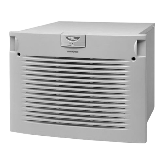
Chapter 1 The Contivity 4600 Introduction The Contivity 4600 is capable of providing scalable, secure, manageable virtual private network (VPN) access for up to 5000 simultaneous users across the public data network (PDN). Figure 1 shows the front view of the Contivity 4600. -
Page 20: Physical Specifications And Operating Environment
20 Chapter 1 The Contivity 4600 Physical specifications and operating environment Table 1 lists the physical specifications and operating environment needed by the switch. Table 1 Physical specifications and operating environment Physical Depth 17 in (43.2 cm) Width 17 in (43.2 cm) -
Page 21: Components And Accessories
Chapter 1 The Contivity 4600 21 Components and accessories Table 2 lists all of the components and accessories of the Contivity 4600. If for any reason you have not received all of the materials listed, please contact Nortel Networks Customer Service. -
Page 22: Optional Sliding Rail Bracket Set
22 Chapter 1 The Contivity 4600 Optional sliding rail bracket set Table 3 lists the components of the optional sliding rail bracket set. Table 3 Optional sliding rail bracket set Description Quantity Slides Slide locking brackets Extender brackets Screws, #8-32 x 3/8 long, 100-degree flathead,... -
Page 23: Healthcheck Entries
Chapter 1 The Contivity 4600 23 Healthcheck entries Note: The hardware Healthcheck entries shown in Table 4 supported. The range parameters are unknown and left to the Intelligent Platform Management Interface (IPMI) firmware delivered on the system board. Table 4 Healthcheck entries... - Page 24 24 Chapter 1 The Contivity 4600 311641-A Rev 00...
-
Page 25: Chapter 2 Cabling The Switch
Connect the 10/100BASE-TX LAN RJ-45 connector to the switch. Optionally, connect the LAN or WAN card cables. Connect the power cords to the back of the switch and to the electrical outlet. Installing the Contivity 4600... -
Page 26: Figure 2 Back View Of The Contivity 4600
26 Chapter 2 Cabling the Switch Figure 2 shows the back view of the Contivity 4600. Figure 2 Back view of the Contivity 4600 Reset Power Serial CS460002A 311641-A Rev 00... -
Page 27: Power Cord Requirements
IEC 320, Sheet C13, female. Cord length and flexibility The power cord must be less than 4.5 meters (14.7 feet) long, and it must be a flexible HAR (harmonized) cord or VDE-certified cordage to comply with the switch's safety certifications. Installing the Contivity 4600... -
Page 28: Lan Interface Connections
28 Chapter 2 Cabling the Switch LAN interface connections At least one LAN interface connection is for Web management. 100BASE-TX connections require Category 5, twisted-pair wire. The 100BASE-TX specification supports 100 Mb/s transmission over two pairs of Category 5 twisted-pair Ethernet wiring, one pair each for transmit and receive operations. -
Page 29: Dual V.35 Wan Interface (Optional)
V.35 interface. Figure 4 Dual V35 interface CS260016A The cables provided with the WAN PCI card enable the WAN adapter to function as DTE (Data Terminal Equipment). Table 5 shows the DB26S-to-V.35 cable pinouts. Installing the Contivity 4600... -
Page 30: Table 5 Db26S-To-V.35 Cable Pinouts (Dual Interface)
30 Chapter 2 Cabling the Switch Table 5 DB26S-to-V.35 cable pinouts (dual interface) Standard-wired end Pair # & Special-wired end Signal name 26-pin male conductor 34-pin male pair 1A pair 1B pair 2A pair 2B pair 3A pair 3B pair 4A pair 4B pair 5A pair 5B... -
Page 31: Single Wan Interface V.35/X.21 (Optional)
DTE (Data Terminal Equipment). Figure 5 shows the single V.35/X.21 WAN interface. Figure 5 Single V.35/X.21 WAN interface (single interface) Table 6 on the following page shows the DB28S-to-V.35 cable pinouts. Table 7 shows the DB28S-to-X.21 cable pinouts. Installing the Contivity 4600... -
Page 32: Table 6 Db28S-To-V.35 Cable Pinouts
32 Chapter 2 Cabling the Switch Table 6 DB28S-to-V.35 cable pinouts Standard-wired end Pair # & Special-wired end Signal name Notes 28-pin male conductor 34-pin male TXDA pair 1A TXDB pair 1B RXDA pair 2A RXDB pair 2B TXCA pair 3A TXCB pair 3B RXCB... -
Page 33: Table 7 Db28S-To-X.21 Cable Pinouts
5. Wires of pair 4 connect to wires of pair 5, but not to any pins in the DA-15. Do NOT interconnect Shield to Signal Ground – they are separate signals. 6. The pair suffix A or B refers to an individual wire within a twisted pair. Installing the Contivity 4600... -
Page 34: T1 Csu/Dsu Wan Interface
34 Chapter 2 Cabling the Switch T1 CSU/DSU WAN interface Note: The T1 CSU/DSU WAN interface cable is not supplied by Nortel Networks. This cable has 8-pin male connectors on each end. The T1 CSU/DSU WAN crossover cable crosses the blue wire pair with the orange wire pair. This is different from the commonly available crossover cable used for 10BaseT, which crosses the green wire pair with the orange wire pair. -
Page 35: Table 8 T1 Csu/Dsu Cable Pinouts
The cable will operate properly if pins 3, 6, 7, and 8 are not connected. Warning: Do not use Ethernet cable. The T1 CSU/DSU will appear to work, but will not work to specifications. Data may be corrupted. Installing the Contivity 4600... -
Page 36: T3 Hssi Interface (Optional)
36 Chapter 2 Cabling the Switch T3 HSSI interface (optional) The single T3 WAN connection is located on a PCI card that has a 50-pin SCSI II female connector that provides the signals needed to interface to a T3 modem or modem eliminator. - Page 37 Chapter 2 Cabling the Switch 37 Table 9 T3 HSSI cable pinouts (continued) TESTB TESTA Installing the Contivity 4600...
- Page 38 38 Chapter 2 Cabling the Switch 311641-A Rev 00...
-
Page 39: Chapter 3 Rack Mounting
Chapter 3 Rack Mounting This chapter describes how to mount the Contivity 4600 into a chassis rack. Included are standard rack-mounting considerations that Nortel Networks recommends. Warning: The Contivity 4600 weighs about 60 pounds and should always be carried by two people... - Page 40 40 Chapter 3 Rack Mounting Use the rack-mounting hardware that came with your switch to complete the following steps: Install the long bottom mounting brackets onto the rack. Install the side mounting brackets onto the unit. Slide the unit into the rack on top of the horizontal bottom mounting brackets. Secure the unit’s vertical rack-mount brackets to the vertical rack rails.
-
Page 41: Figure 8 Attaching Mounting Brackets To A Contivity 4600
Chapter 3 Rack Mounting 41 Figure 8 Attaching mounting brackets to a Contivity 4600 Side mounting bracket Mounting rail Bottom mounting bracket CS460004A Installing the Contivity 4600... - Page 42 42 Chapter 3 Rack Mounting 311641-A Rev 00...
-
Page 43: Changing The Hardware Configurations
To replace power supplies, replace hard disk drives, or access the diskette drive for system recovery operations, you must remove the switch’s front bezel. Note: Removing the front bezel on the Contivity 4600 activates the chassis intrusion alarm on power only. This intrusion is reported to the system log file. - Page 44 Figure 9 shows you how to remove the front bezel from the Contivity 4600. You do not need to turn off the switch to remove the front bezel when installing a power supply or hard disk drive.
-
Page 45: Figure 9 Removing The Contivity 4600 Front Bezel
Chapter 4 Changing the Hardware Configurations 45 Figure 9 Removing the Contivity 4600 front bezel Using a Phillips screwdriver, rotate screws a quarter turn counter-clockwise (top right and left corners), then seperate ball stud on bezel from socket on chassis (middle of both sides and bottom right and left corners). -
Page 46: Figure 10 Contivity 4600 Front Components
46 Chapter 4 Changing the Hardware Configurations Figure 10 shows the Contivity 4600 front components. Figure 10 Contivity 4600 front components Floppy drive Alert/Fail Boot/Ready Disk drives Power supplies CS460006A 311641-A Rev 00... -
Page 47: Contivity 4600 System Board Layout
Contivity 4600 system board layout This section shows the Contivity 4600 system board. Figure 11 shows a sample Contivity 4600 system board, including the Dual Inline Memory Modules (DIMMs) and peripheral component interconnect (PCI) slots. Figure 11 Sample Contivity 4600 system board slots... -
Page 48: Figure 12 Installing Contivity 4600 Lan/Wan And Hardware Accelerator Cards
Populate the slots from Slot 1 to Slot 6 (top to bottom), in that order, as shown Figure Figure 12 Installing Contivity 4600 LAN/WAN and hardware accelerator cards CS460014A Secure the option card in the tray with the slot filler panel screw. -
Page 49: Installing Contivity 4600 Dimms
Installing Contivity 4600 DIMMs Figure 6 shows you how to unlock a DIMM in the Contivity 4600, and remove or install a DIMM. Install a DIMM in the next available slot (for example, if the DIMM #1 slot is populated, then add the next DIMM to the DIMM #2 slot). -
Page 50: Replacing A Contivity 4600 Power Supply
Replace the support bracket by tightening the two secured captive screws and the rear Phillips screw. Push in the slide-out tray and tighten the thumb-screws. Replacing a Contivity 4600 power supply To remove the power supply: Remove the front bezel as shown in... -
Page 51: Figure 14 Removing A Contivity 4600 Power Supply
Chapter 4 Changing the Hardware Configurations 51 Figure 14 Removing a Contivity 4600 power supply CS460010A Grab the handle and pull the power supply firmly, until the device disengages. Be careful of the sharp sheet-metal edges. Insert the new power supply. Make sure it seats firmly in its socket and is locked in. -
Page 52: Replacing A Contivity 4600 Hard Disk Drive
52 Chapter 4 Changing the Hardware Configurations Replacing a Contivity 4600 hard disk drive Figure 15 shows you how to replace Contivity 4600 hard disk drives for the switch. Caution: Hard disks are not hot-swappable. To replace a hard disk drive, you must do the following:... -
Page 53: Figure 15 Removing A Contivity 4600 Hard Disk Drive
Chapter 4 Changing the Hardware Configurations 53 Figure 15 Removing a Contivity 4600 hard disk drive Drive 0 Drive 1 Insert and turn key, then remove hard disk by handle. CS460011A Insert the replacement hard drive fully, and lock it by turning the key clockwise. - Page 54 54 Chapter 4 Changing the Hardware Configurations 311641-A Rev 00...
-
Page 55: Assigning A System Identity
To configure the switch from the Serial Interface Configuration menu, you must first connect the serial interface cable to the switch. Then you can use a terminal emulation application, such as HyperTerminal*, to enter the management IP address, subnet mask, and default gateway (optional). Installing the Contivity 4600... -
Page 56: Startup Configuration Requirements
56 Chapter 5 Assigning a System Identity Startup configuration requirements This section describes the fields that you must complete with either the IP Address Configuration utility or the Serial Interface Configuration menu procedure. Management IP address Enter a management IP address for the system. You need this address to manage all system services, such as HTTP, FTP, and SNMP. -
Page 57: Ip Address Configuration Utility
Insert the diskette into the A: drive and select Start → Run, and then type: a:\ExtNetIP.exe or open the My Computer icon on the desktop and open the 3½ Floppy (A:) drive, and then double-click on the icon shown in Figure Installing the Contivity 4600... -
Page 58: Figure 16 Extnepip .Exe Icon
58 Chapter 5 Assigning a System Identity Figure 16 ExtNepIP .exe icon The display shown in Figure 17 appears while the program searches for an unconfigured switch. Figure 17 Serial number search display The program automatically enters the serial number for the first available switch into the table of Contivity switches.As shown in Figure 18, a menu... -
Page 59: Figure 18 Extranet Address Configuration Utility Display
Note: If you move the switch from one network to another, change the Management IP address and subnet mask accordingly. You can obtain help from the extNetIP.hlp file, which is the IP Address Configuration Utility Help file. Installing the Contivity 4600... -
Page 60: Serial Interface Configuration
This interface allows you to give the switch a management IP address and subnet mask so that you can use a Web browser for management. An alternative to the Serial Interface configuration is to use the Nortel Networks IP Address Configuration utility, which Nortel Networks recommends for an initial configuration (refer to “Chapter 3, Startup Configuration Requirements”... - Page 61 Web browser with an invalid address. Note: Before proceeding, verify that you have selected a management IP address routable on the subnet attatched to the private interface of the switch and have this information available. Installing the Contivity 4600...
- Page 62 62 Chapter 5 Assigning a System Identity After the user name and password have been entered, the following menu appears: Main Menu: System is currently in NORMAL mode. 1) Interfaces 2) Administrator 3) Default Private Route Menu 4) Default Public Route Menu 5) Create A User Control Tunnel(IPsec) Profile 6) Restricted Management Mode FALSE 7) Allow HTTP Management TRUE...
- Page 63 Web browser. This administrator’s user ID (default=admin) and password (default=setup) combination is also called the primary administrator. This person always has access to all screens and controls, including the serial port and the recovery disk. There can be only one primary administrator. Installing the Contivity 4600...
- Page 64 64 Chapter 5 Assigning a System Identity For detailed information on configuring and managing the switch, refer to Configuring the Contivity VPN Switch, Chapter 3, “Configuring the Switch,” which describes topics such as: • Licensing • The IP Address Configuration utility •...
-
Page 65: Using The Recovery Diskette
Restore the factory default configuration or the backup configuration. • Reformat the switch’s hard disk. • Apply a new software version to the switch. • Perform file maintenance. • View the Event log. • Restart the system. Installing the Contivity 4600... -
Page 66: Figure 19 Recovery Diskette Display
66 Chapter 6 Using the Recovery Diskette Figure 19 Recovery diskette display 311641-A Rev 00... - Page 67 The serial number uniquely identifies each switch’s backup data. A blank row in the server backup field always appears to allow you to manually enter a backup server in case you did not configure automatic backup server locations. Installing the Contivity 4600...
- Page 68 Alternatively, a new factory default software image and file system can be restored to the switch’s hard disk. Specify the name or address and path of the network file server onto which the software from the Nortel Networks CD has been installed.
- Page 69 Then reposition your Web browser to the Management IP address, and click on Reload or Refresh from your browser menu to access the management page of the software running on the hard disk. Installing the Contivity 4600...
- Page 70 70 Chapter 6 Using the Recovery Diskette 311641-A Rev 00...
-
Page 71: Index
60 HTTP management 58 connecting cables 25 conventions 15 installation 40 conventions, text 15 IP address 56 customer support 18 configuration utility 59 DB26S-to-X.21 cable pinouts 33 management default gateway 56 IP address serial configuration 58 Installing the Contivity 4600... - Page 72 65 reset button 69 RJ-45 pinouts 28 safety 43 serial interface configuration 60 prerequisites 60 serial number 67 software version 68 new 65 support, Nortel Networks 18 system board illustration 47 system identity assigning 55 311641-A Rev 00...