Ariens Power Brush 36 Operator's Manual
Hide thumbs
Also See for Power Brush 36:
- Manual (32 pages) ,
- Operator's manual (32 pages) ,
- Owner's/operator's manual (34 pages)

Related Manuals for Ariens Power Brush 36


Summary of Contents for Ariens Power Brush 36
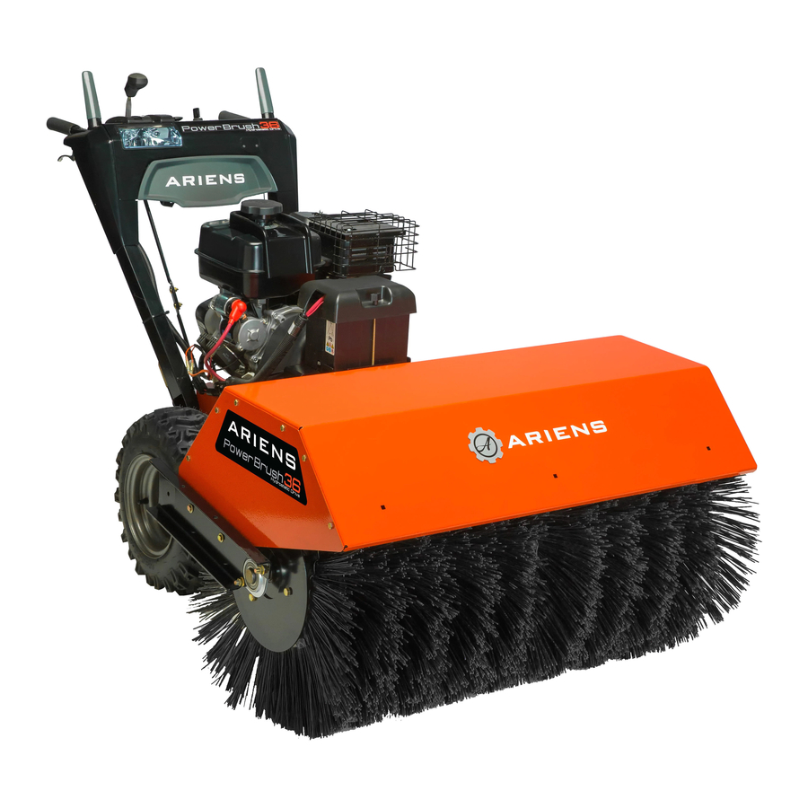
- Page 1 Power Brush 36 Operator’s Manual Manuel du Utilisateur Model 926074 – Power Brush 36 (SN 000101 +) ENGLISH • 05175300B 12/19 FRANÇAIS Printed in USA...
-
Page 2: Table Of Contents
TABLE OF CONTENTS WELCOME ..... . 1 Transport Unit ....13 Adjust Engine Air Cleaner . -
Page 3: Welcome
WELCOME Congratulations on your purchase and welcome to the Ariens family! Every machine in the Ariens lineup is designed for long-lasting and unsurpassed performance. We are confident your machine will be part of your family for many years to come. -
Page 4: Safety
• OBEY THE MESSAGE! penalties. Emission controls and components can only be adjusted by an Ariens dealer or SIGNAL WORDS an authorized engine manufacturer's service The safety alert symbol above and signal center. Contact your Ariens Equipment... -
Page 5: Safety Decals
4. Notice Safety Decal Descriptions NOTICE: Indicates information or procedures 1. WARNING! that are considered important but not hazard related. If not followed, property damage could result. WARNING! 5. Important IMPORTANT: Indicates general reference information worthy of special attention. SAFETY DECALS NEVER direct discharge towards persons or property The safety decals on your unit are visual... -
Page 6: Safety Rules
SAFETY RULES 3. DANGER! The following safety instructions are based on the B71.3 specifications of the American National Standards Institute in effect at the DANGER! time of production. Training Read, understand and follow all instructions on the unit and in the manual(s) before operating this unit. - Page 7 Handle fuel with care; it is highly flammable. DO NOT touch parts which might be hot from operation. Allow parts to cool before • Use an approved fuel container. attempting to maintain, adjust or service. • NEVER add fuel to a running engine or hot engine.
- Page 8 Disengage attachment when not in use and Keep unit free of ice or other debris. Clean when traveling from one work area to up oil or fuel spills. another. ALWAYS keep protective structures, guards, Disengage power to the attachment when and panels in good repair and secured in unit is transported or not in use.
- Page 9 Use a slow speed to avoid stops or shifts on Towing/Transporting slopes. Avoid starting or stopping on a ALWAYS stop engine, remove key and close slope. DO NOT park unit on a slope unless fuel valve or drain fuel when transporting absolutely necessary.
-
Page 10: Controls & Features
CONTROLS & FEATURES Figure 3 1. Traction Drive Clutch Lever 11. Throttle Control Lever 2. Attachment Clutch Lever 12. Fuel Valve 3. Speed Selector Lever 13. Engine Key 4. Brush Lock Trigger 14. Electric Start Button 5. Brush Guard 15. Oil Fill / Dipstick 6. -
Page 11: Engine Key
CHOKE CONTROL LEVER WARNING: Read and See Figure 6. understand the Safety section Controls airflow to the engine. before proceeding. See Figure 3 for all controls and features locations. ENGINE KEY See Figure 4. Controls power to the engine. The key cannot be removed when in run position. -
Page 12: Speed Selector Lever
SPEED SELECTOR LEVER TRACTION DRIVE CLUTCH LEVER (LEFT SIDE) See Figure 8. Controls the speed of forward and reverse See Figure 10. travel. Allows unit to travel in forward and in reverse. Figure 10 BRUSH LOCK TRIGGER Figure 8 See Figure 11. Unlocks and locks brush to change clearing ATTACHMENT CLUTCH LEVER angle. -
Page 13: Operation
E85 blended fuels; the engine is not E20 / work areas. E30 / E85 compatible. The maximum recommended ethanol content is 10%. Ariens NOTICE: Release both clutch levers before recommends using a quality fuel stabilizer in changing speed. When the unit is turned left all fuel. -
Page 14: Set Brush Height
SET BRUSH HEIGHT 2. Raise brush: a. Remove lynch pins from caster shaft tops. CAUTION: AVOID INJURY. If brush height is too low, brush b. Remove desired amount of height can drive machine rearward adjuster clips from caster shaft tops when attachment clutch is and install onto lower caster shaft engaged. -
Page 15: Set Brush Angle
SET BRUSH ANGLE ADJUST ENGINE AIR CLEANER See Figure 14. See Figure 15. 1. Squeeze brush lock trigger to unlock 1. Pull down latches and move tabs away brush position. from base to release air cleaner cover. 2. Move handlebars left or right until brush is in desired position. -
Page 16: Maintenance
MAINTENANCE Normal Position WARNING: Read and understand the Safety section before proceeding. Your Ariens dealer can provide service and adjustments to keep your unit operating at peak efficiency. Contact an authorized engine manufacturer’s service center for engine service. SERVICE POSITION WARNING: AVOID INJURY. - Page 17 See Figure 17. 9. Remove hardware securing brush lock trigger to handlebar and allow trigger to 6. Remove hardware securing belt finger rest on brush attachment. See Figure 19. and remove belt finger. 7. Remove attachment drive belts from attachment sheave. 1.
-
Page 18: Return Unit To Operating Position
See Figure 21. CAUTION: AVOID ENGINE DAMAGE. Do not leave unit in service position for longer than 30 minutes. Allow 30 minutes for oil to return to crankcase before starting engine. 12. Slowly rotate tractor / frame forward so unit rests on attachment sheave. Protect attachment sheave so it does not incur damage. -
Page 19: Maintenance Schedule
* See Add Fuel Stabilizer on page 17. ** Refer to engine manual for instructions. SERVICE PARTS Figure 22 See your Ariens dealer to purchase service parts for your unit. 9. Reinstall belt cover and secure with Description Part No. -
Page 20: Engine Oil
CHECK TIRE PRESSURE LUBRICATE UNIT Keep tires inflated to pressure listed on tire sidewall. Ariens recommends using Ariens Hi-Temp Grease or equivalent (see Service Parts on WARNING: AVOID INJURY. page 17) to lubricate fittings. Lubricate each Explosive separation of tire and season or every 25 hours of operation. -
Page 21: Adjustments
Casters See Figure 23. Figure 25 Figure 23 3. Return unit to operating position. See Return Unit to Operating Position on Traction Drive page 16. 1. Place unit in service position. See Service Position on page 14. ADJUSTMENTS 2. Lubricate as shown in Figure 24 and Figure 25. -
Page 22: Adjust Attachment Clutch
9. Check forward and reverse speeds. 5. Loosen jam nut on cable adjustment barrel, and then turn the adjustment a. Start unit, position speed selector barrel down to shorten cable and remove lever in the first forward position and cable slack. See Figure 27. engage traction drive clutch. - Page 23 Check Belt Finger Clearance 9. Reconnect spark plug wire. See Figure 30. Check Attachment Idler Arm Clearance With the attachment clutch engaged, the belt finger located opposite the belt idler must be See Figure 29. less than 3.2 mm (1/8") from belts, but must 1.
-
Page 24: Adjust Traction Drive Clutch
ADJUST TRACTION DRIVE CLUTCH See Figure 31. If unit does not drive correctly, adjust traction clutch to compensate for friction disc wear. 1. Stop engine, wait for all moving parts to stop and for hot parts to cool. 2. Disconnect spark plug wire. 1. -
Page 25: Troubleshooting
(flooded). and reattempt starting. See Start The Engine on page 11. Engine is faulty. See your Ariens dealer or authorized engine manufacturer’s service center. Fuel mixture is too rich. Move choke control lever to off position. See Choke Control Lever on page 9. - Page 26 TROUBLESHOOTING Problem Probable Cause Correction Attachment clutch not adjusted Adjust attachment clutch. See Adjust properly. Attachment Clutch on page 20. Debris is caught in brush. Stop engine, wait for moving parts to stop and for hot parts to cool. Remove obstruction before restarting.
-
Page 27: Storage
ACCESSORIES SHORT TERM 1. Tighten all hardware to correct See your Ariens dealer for a complete list of specifications. compatible accessories and attachments for 2. Inspect unit for visible signs of wear or your unit. -
Page 28: Specifications
SPECIFICATIONS Model Number 926074 Engine Engine Model Kohler CH395 Gross Torque* – N•m (lb-ft) 18.8 (13.9) 277 (16.9) Displacement – cc (in Maximum RPM – No Load 3750 ± 100 Starter 120V Electric and Recoil Fuel Refer to Engine Manual Tank Capacity –... -
Page 29: Warranty
“Commercial Use.” If any product is rented or leased, then the duration of these warranties shall be 90 days after the date of purchase. An authorized Ariens dealer will repair any defect in material or workmanship, and repair or replace any defective part, subject to the conditions, limitations and exclusions set forth herein. Such repair or replacement will be free of charge (labor and parts) to the original purchaser;... - Page 30 Exclusions – Items Not Covered by This Warranty • Parts that are not genuine Ariens service parts are not covered by this warranty and may void the war- ranty if the parts result in premature wear or damage to the product.
- Page 31 Parts and Accessories Service replacement parts and non-serialized accessories are warranted for 90 days from date of purchase. Parts and accessories must be installed by an authorized Ariens dealer to be covered. Labor is not included. Customer Responsibilities Register the product immediately at the time of sale. If the dealer does not register the product, the customer must register the unit on-line at www.ariens.com.
- Page 32 Disclaimer AriensCo may from time to time change the design of its products. Nothing contained in this warranty shall be construed as obligating the AriensCo to incorporate such design changes into previously manufactured products, nor shall such changes be construed as an admission that previous designs were defective. Limitation of Remedy and Damages AriensCo liability under this warranty, and under any implied warranty that may exist, is limited to repair of any defect in workmanship, and repair or replacement of any defective part.
- Page 33 655 West Ryan Street Brillion, WI 54110 www.ariens.com parts.ariens.com...