Advertisement
Quick Links
Service Manual
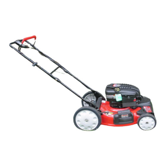
2005 500 Series (569) Self Propelled Walk Behind Mower
NOTE: These materials are for use by trained technicians who are experienced in the service and repair of outdoor power
equipment of the kind described in this publication, and are not intended for use by untrained or inexperienced individuals.
These materials are intended to provide supplemental information to assist the trained technician. Untrained or inexperi-
enced individuals should seek the assistance of an experienced and trained professional. Read, understand, and follow all
instructions and use common sense when working on power equipment. This includes the contents of the product's Oper-
ators Manual, supplied with the equipment. No liability can be accepted for any inaccuracies or omission in this publication,
although care has been taken to make it as complete and accurate as possible at the time of publication. However, due to
the variety of outdoor power equipment and continuing product changes that occur over time, updates will be made to these
instructions from time to time. Therefore, it may be necessary to obtain the latest materials before servicing or repairing a
product. The company reserves the right to make changes at any time to this publication without prior notice and without
incurring an obligation to make such changes to previously published versions. Instructions, photographs and illustrations
used in this publication are for reference use only and may not depict actual model and component parts.
© Copyright 2005 MTD Products Inc. All Rights Reserved
MTD Products Inc - Product Training and Education Department
FORM NUMBER - 769-02088
10/2005
Advertisement

Related Manuals for MTD 2005 500 Series


Summary of Contents for MTD 2005 500 Series
- Page 1 Service Manual 2005 500 Series (569) Self Propelled Walk Behind Mower NOTE: These materials are for use by trained technicians who are experienced in the service and repair of outdoor power equipment of the kind described in this publication, and are not intended for use by untrained or inexperienced individuals.
-
Page 3: Table Of Contents
TABLE OF CONTENTS Introduction ........................... 1 Belt Removal ........................1 Blade Removal ........................3 Traction Control Cable Removal ..................3 Engine Control Cable ......................4 Transmission Removal/Replacement ................... 5 Rear Discharge Door Removal/Replacement ..............6 Servicing Front Wheel Brackets ................... 9... -
Page 5: Introduction
SERIES 569 SELF PROPELLED SERIES 569 SELF PROPELLED INTRODUCTION BELT REMOVAL 1.1. Disclaimer: This service manual was intended 2.1. Disconnect and ground the spark plug wire. for the use, by trained technicians. The informa- 2.2. Drain out any fuel that is in the fuel tank. tion contained in this manual is current and accurate at the time of writing, but is subject to 2.3. - Page 6 SERIES 569 SELF PROPELLED 2.5. Loosen the belt guide with a pair of 7/16” 2.7. Position the mower on its left side to keep the air wrenches. See Figure 2.5. cleaner and carburetor elevated. NOTE: Due to the orientation of the vent on the transmission positioning the mower on its left side is also advisable 2.8.
-
Page 7: Blade Removal
SERIES 569 SELF PROPELLED 2.10. When installing the new belt be sure that the belt TRACTION CONTROL CABLE REMOVAL is riding within the belt keepers. 4.1. Disconnect and ground the spark plug wire. See Figure 2.10. 4.2. Remove the belt cover. 4.3. -
Page 8: Engine Control Cable
SERIES 569 SELF PROPELLED 4.7. Remove the two Phillips head screws on the bot- ENGINE CONTROL CABLE tom of the control panel housing. See Figure 4.7. 5.1. Push the bail handle to the forward limit of its travel to give the cable slack. 5.2. -
Page 9: Transmission Removal/Replacement
SERIES 569 SELF PROPELLED 6.7. When removing the drive gears be careful of the TRANSMISSION REMOVAL/REPLACEMENT dowel pins not to lose them. See Figure 6.7. 6.1. Remove the belt cover by removing the shoulder screws, squeeze the housing together to clear the tabs that go into the wheel bracket. -
Page 10: Rear Discharge Door Removal/Replacement
SERIES 569 SELF PROPELLED 6.10. Install the transmission in reverse order of dis- REAR DISCHARGE DOOR REMOVAL/ asembly. See Figure 6.10. REPLACEMENT 7.1. Elevate the rear of mower with a couple of 4X4 blocks or similar material. See Figure 7.1. Figure 6.10 NOTE: Make sure the front baffle is lined up with Figure 7.1... - Page 11 SERIES 569 SELF PROPELLED 7.3. Remove both wheels with a 9/16” socket. 7.6. Remove the 2 socket head screws from the rear See Figure 7.3. on the mower using a T-80 Torx driver. See Figure 7.6. Socket head screws Figure 7.3 Figure 7.6 NOTE: The height adjuster lever can remain on the wheel brackets.
- Page 12 SERIES 569 SELF PROPELLED 7.8. Discharge the torsion springs that hold the rear 7.10. Remove the self tapping screws that stabilize door closed. See Figure 7.8. handle brackets on each side of the deck. See Figure 7.10. Self-tapping screw 3/8” wrench size 9/16”...
-
Page 13: Servicing Front Wheel Brackets
SERIES 569 SELF PROPELLED 7.13. When reinstalling the torsion spring, use a piece 8.2. After removing the wheel bracket you will need of rope or a spring puller to pull back on the to take off the snap ring that holds the assembly spring to avoid the possibility of injury. - Page 14 SERIES 569 SELF PROPELLED 8.4. During reassembly it may be necessary to com- 8.7. Center the wrench to allow enough room to put press the wave washer in order to reinstall the the snap ring on. See Figure 8.7. snap ring. See Figure 8.4. Wrench Snap Ring Figure 8.7...