Table of Contents
Advertisement
Quick Links
Advertisement
Table of Contents

Related Manuals for Omron Sysmac FHV Series


Summary of Contents for Omron Sysmac FHV Series
- Page 1 Vision Sensor FHV Series Smart Camera Setup Manual FHV7£-£££££-£££-££ Z408-E1-06...
- Page 2 No patent liability is assumed with respect to the use of the information contained herein. Moreover, because OMRON is constantly striving to improve its high-quality products, the information con- tained in this manual is subject to change without notice. Every precaution has been taken in the preparation of this manual.
-
Page 3: Intended Audience
Introduction Introduction Thank you for purchasing the FHV Series Smart Camera. This manual contains information that is necessary to use the FHV Series Smart Camera. Please read this manual and make sure you understand the functionality and performance of the FHV Series Smart Camera before you attempt to use it in a control system. -
Page 4: Relevant Manuals
Relevant Manuals Relevant Manuals The following table provides the relevant manuals for this product. Read all of the manuals that are relevant to your system configuration and application before you use this product. Manual Basic information Information Reference Matrix Overview of FHV7 series Setup and Wiring EtherCAT EtherNet/IP... - Page 5 Relevant Manuals Manual Basic information Information Reference Matrix Create and Set the Scene EtherCAT EtherNet/IP PROFINET Ethernet RS-232C Parallel interface Optimizing the Scene Flow EtherCAT EtherNet/IP PROFINET Ethernet RS-232C Parallel interface Connecting the Controller EtherCAT EtherNet/IP PROFINET Ethernet RS-232C Parallel interface Using Helpful Functions EtherCAT EtherNet/IP...
-
Page 6: Manual Structure
Manual Structure Manual Structure Page Structure The following page structure is used in this manual. Level 1 heading 4 Installation and Wiring Level 2 heading Level 3 heading Mounting Units Level 2 heading Gives the current Level 3 heading headings. 4-3-1 Connecting Controller Components The Units that make up an NJ-series Controller can be connected simply by pressing the Units together... -
Page 7: Special Information
Manual Structure Special Information Special information in this manual is classified as follows: Precautions for Safe Use Precautions on what to do and what not to do to ensure safe usage of the product. Precautions for Correct Use Precautions on what to do and what not to do to ensure proper operation and performance. Additional Information Additional information to read as required. - Page 8 Manual Structure FHV Series Smart Camera Setup Manual (Z408-E1)
- Page 9 Sections in This Manual Sections in This Manual Confirm the Package Overview of FHV series Configuration Handling and Installation Environment Installation Power Supply and I/O Interface Software Setup Index FHV Series Smart Camera Setup Manual (Z408-E1)
-
Page 10: Table Of Contents
Symbols and the Meanings for Safety Precautions Described in This Manual ..........15 Meanings of Alert Symbols ..........................15 Warning................................16 Precautions for Safe Use ..................18 Condition of the Fitness of OMRON Products ....................18 Installation Environment ..........................18 Power Supply and Wiring ..........................18 Mounting ................................19 Others ................................20... - Page 11 CONTENTS Section 1 Confirm the Package Smart Camera.........................1-2 1-1-1 FHV7£-£££££-C Series......................1-2 1-1-2 FHV7£-£££££-S££ Series ....................1-2 1-1-3 FHV7£-£££££-H££ Series ....................1-3 1-1-4 FHV7£-£££££-S££-££ Series..................1-3 1-1-5 FHV7£-£££££-H££-££ Series..................1-4 Sold Separately ........................1-5 1-2-1 Smart Camera Data Unit ......................1-5 1-2-2 Cables ............................1-5 1-2-3 Modules............................1-9 1-2-4 Accessories ..........................1-10 1-2-5 Lighting and Lighting Controller ....................1-12...
- Page 12 CONTENTS 3-10-1 Specifications ..........................3-79 3-10-2 Dimensions ..........................3-79 3-11 Waterproof Caps ........................3-81 3-11-1 Specifications ..........................3-81 3-11-2 Dimensions ..........................3-81 3-12 Lightproof Sheet ........................3-83 3-12-1 Specifications ..........................3-83 3-12-2 Dimensions ..........................3-83 3-13 Special Covers ........................3-84 3-13-1 Specifications ..........................3-84 3-13-2 Dimensions ..........................3-84 3-14 Replacement Screws for Micro SD Card Cover ..............3-86 3-14-1 Specifications ..........................3-86 3-14-2...
- Page 13 CONTENTS 6-5-2 Pin Layout ..........................6-24 Interface for the Data Unit for Smart Camera..............6-25 6-6-1 Cables / I/O Connectors, and Terminals ...................6-26 6-6-2 Pin Layout ..........................6-28 6-6-3 Parallel Interface Specifications ....................6-31 6-6-4 I/O Interface Input/Output Circuit Diagrams ................6-33 6-6-5 EtherCAT Interface Specifications (FHV-SDU30) ..............6-36 Inserting and Removing the MicroSD Card...............6-38 6-7-1 How to Insert / Remove the MicroSD Card ................6-38...
-
Page 14: Terms And Conditions Agreement
Omron’s exclusive warranty is that the Products will be free from defects in materials and work- manship for a period of twelve months from the date of sale by Omron (or such other period ex- pressed in writing by Omron). Omron disclaims all other warranties, express or implied. -
Page 15: Application Considerations
WAY CONNECTED WITH THE PRODUCTS, WHETHER SUCH CLAIM IS BASED IN CONTRACT, WARRANTY, NEGLIGENCE OR STRICT LIABILITY. Further, in no event shall liability of Omron Companies exceed the individual price of the Product on which liability is asserted. Application Considerations... - Page 16 Product. Errors and Omissions Information presented by Omron Companies has been checked and is believed to be accurate; how- ever, no responsibility is assumed for clerical, typographical or proofreading errors or omissions. FHV Series Smart Camera Setup Manual (Z408-E1)
-
Page 17: Safety Precautions
Safety Precautions Safety Precautions Symbols and the Meanings for Safety Precautions Described in This Manual The following notation is used in this manual to provide precautions required to ensure safe usage of a Sensor Controller. The safety precautions that are provided are extremely important to safety. Always read and heed the information provided in all safety precautions. -
Page 18: Warning
Safety Precautions Warning WARNING This product must be used according to this manual and Instruction Sheet. Failure to observe this may result in the impairment of functions and performance of the product. This product is not designed or rated for ensuring the safety of persons. Do not use it for such purposes. - Page 19 Safety Precautions When using an intranet environment through a global address, connecting to an unauthor- ized terminal such as a SCADA, HMI or to an unauthorized server may result in network se- curity issues such as spoofing and tampering. You must take sufficient measures such as re- stricting access to the terminal, using a terminal equipped with a secure function, and locking the installation area by yourself.
-
Page 20: Precautions For Safe Use
Applications under conditions and environment not described in specifications. 1. In addition to the applications listed from (a) to (d) above, Omron products (see definition) are not intended for use in vehicles designed human transport (including two wheel vehicles). Please do NOT use Omron products for vehicles designed human transport. -
Page 21: Mounting
- When attaching the lighting module, use S8VK-G12024 (OMRON) or S8VS-12024 (OMRON). - When not attaching the lighting module, use S8VK-G06024 (OMRON) or S8VS-06024 (OMRON). • Wire high-voltage cables or power cables are separated from the cables of this product. If the same cable or duct is used, the product may receive induction and it may cause malfunctioning or break- age. -
Page 22: Others
• If anything abnormal occurs, for example, strange smell/sound is detected, the main unit gets very hot, or a smoke comes, stop using the product, turn OFF the product, and consult OMRON’s branch or sales office. • Do not disassemble, deform by pressurizing, incinerate, repair, or alter this product. -
Page 23: Precautions For Correct Use
• If the power supply line has surge, connect a surge absorber according to the operational environ- ment to use the product. • To use the product in an environment with strong noise, use a noise filter (Omron's S8V-NFS206 or equivalent) for the smart camera's power input block. -
Page 24: Maintenance
Precautions for Correct Use • After turning off the power, wait at least 1 second before restarting. • When the camera-mount lighting controller (FL-TCC1PS) or the external lighting (FL-MD£MC) is used, be sure to attach the junction cable (FHV-VFLX-GD) between the Smart Camera and the light- ing. -
Page 25: Failsafe Measures
Precautions for Correct Use Failsafe Measures • When operating a stage or robot using measurement results of the Smart Camera (axis moving dis- tance output by the calibration or alignment measurement), take measures as follows: Be sure to operate the stage or robot after confirming the measurement result data on the stage or robot side that the data are within the movable range of the stage or robot. -
Page 26: Led Safety
Precautions for Correct Use Bend Resistant cable (FHV-VNBX2/FHV-VNLBX2, FHV-VDBX2/FHV-VDLBX2, FHV-VUBX2/FHV- VULBX2), or Bend Resistant cable (FHV-VNB2/FHV-VNLB2/FHV-VNB/FHV-VNLB, FHV-VDB2/FHV- VDLB2/FHV-VDB/FHV-VDLB, FHV-VUB2/FHV-VULB2/FHV-VUB/FHV-VULB). LED Safety This product is classified into the following risk groups by IEC62471. Model Color LED safety Display FHV-LTM-W White Risk group 2 FHV-LTM-R Risk group 1 FHV-LTM-IR... -
Page 27: Regulations And Standards
Compatibility Regulations 2016 EN61326-1 Electromagnetic environment : Industrial electromagnetic environment (EN/IEC 61326-1 Table 2) • This product complies with EC/EU Directives. EMC-related performance of the OMRON devices that comply with EC/EU Directives will vary depending on the configuration, wiring, and other conditions of the equipment or control panel on which the OMRON devices are installed. -
Page 28: Related Manuals
Related Manuals Related Manuals The followings are the manuals related to this manual. Use these manuals for reference. Name of Manual Man. No.. Model Purpose Contents Smart Camera 3615629-0 FHV7£-£££££-£££-£ To confirm the safety Describes the definitions of basic FHV Instruction Sheet and usage precau- terms, the meaning of signal words, £... -
Page 29: Terminology
Terminology Terminology Term Definition FHV Series All FHV series model names. Measurement flow (abbre- A continuous flow of measurement processing. A measurement flow consists of a viated as “flow”) scene created from a combination of processing items. Measurement processing Executing processing items for inspections and measurements. Measurement ID Measurement time: YYYY-MM-DD_HH-MM-SS-XXXN (YYYY: Year, MM: Month, DD: Date, HH: Hour, MM: Minute, SS: Second, XXX: Mil-... - Page 30 Terminology Term Definition • Operation mode Double Speed Multi-input A mode that processes the measurement flow for the first trigger and then proc- esses the measurement flow in parallel for the second trigger to achieve a high- speed trigger input interval. It is used together with the multi-input function. •...
- Page 31 Terminology Term Definition Position compensation When the location and direction of measured objects are not fixed, the positional deviation between reference position and current position is calculated and meas- urement is performed after correcting. Please select processing items that are appropriate to the measurement object from processing items that are related to position compensation.
- Page 32 Terminology Term Definition 2's complement Binary numbers are generally used to represent negative numbers. Negative numbers are expressed by Inverting all bits of a positive number and adding 1 to the result. Ex. -1 is expressed as 2's complement. -1 can be calculated by 0-1. (In the case of 1, minus 1) 00000000 (= 0) 00000001 (= 1)
-
Page 33: Revision History
Revision History Revision History A manual revision code appears as a suffix to the catalog number on the front and back covers of the manual. Z408-E1-06 Cat. No. Revision code Revision code Date Revised content Nov. 2018 Original production Jul. 2019 Added Smart Camera data unit and High-speed lens module etc. - Page 34 Revision History FHV Series Smart Camera Setup Manual (Z408-E1)
- Page 35 Confirm the Package Smart Camera ....................1-2 1-1-1 FHV7£-£££££-C Series ................1-2 1-1-2 FHV7£-£££££-S££ Series ..............1-2 1-1-3 FHV7£-£££££-H££ Series..............1-3 1-1-4 FHV7£-£££££-S££-££ Series ............. 1-3 1-1-5 FHV7£-£££££-H££-££ Series ............. 1-4 Sold Separately ....................1-5 1-2-1 Smart Camera Data Unit ................1-5 1-2-2 Cables......................
-
Page 36: Smart Camera
1 Confirm the Package Smart Camera First, please check to see whether the package has all the necessary Smart Camera parts. 1-1-1 FHV7£-£££££-C Series • Smart Camera FHV7£-£££££-C • Connector cap for Ethernet cable (mounted on the body): 1 • Connector cap for an external lighting (mounted on the body): 1 •... -
Page 37: Fhv7£-£££££-S££ Series
1 Confirm the Package 1-1-3 FHV7£-£££££-H££ Series • Smart Camera FHV7£-£££££-H££ • Connector cap for Ethernet cable (mounted on the body): 1 • Connector cap for an external lighting (mounted on the body): 1 • Special cover for FHV-LEM-H (mounted on the body): 1 •... -
Page 38: Fhv7£-£££££-H££-££ Series
1 Confirm the Package 1-1-5 FHV7£-£££££-H££-££ Series • Smart Camera FHV7£-£££££-H££-££ • Connector cap for Ethernet cable (mounted on the body): 1 • Connector cap for an external lighting (mounted on the body): 1 • Instruction sheet: 1 each (Body, lens module, and lighting module) •... -
Page 39: Sold Separately
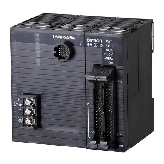
1 Confirm the Package Sold Separately 1-2-1 Smart Camera Data Unit Appearance Description Model Parallel interface for Smart Camera data unit FHV-SDU10 Extension unit for Parallel I/O signals EtherCAT interface for Smart Camera data unit FHV-SDU30 Communication unit for EtherCAT interface 1-2-2 Cables I/O Cables... - Page 40 1 Confirm the Package Appearance Description Model I/O cable bending resistance straight FHV-VDB 2M Cable length: 2 m, 3 m, 5 m, 10 m, 20 m FHV-VDB 3M FHV-VDB 5M FHV-VDB 10M FHV-VDB 20M I/O cable bending resistance right-angle FHV-VDLB 2M Cable length: 2 m, 3 m, 5 m, 10 m, 20 m FHV-VDLB 3M FHV-VDLB 5M...
- Page 41 1 Confirm the Package Appearance Description Model Ethernet cable bending resistance straight FHV-VNB 2M Cable length: 2 m, 3 m, 5 m, 10 m, 20 m FHV-VNB 3M FHV-VNB 5M FHV-VNB 10M FHV-VNB 20M Ethernet cable bending resistance right-angle FHV-VNLB 2M Cable length: 2 m, 3 m, 5 m, 10 m, 20 m FHV-VNLB 3M FHV-VNLB 5M...
- Page 42 1 Confirm the Package Appearance Description Model Smart Camera data unit cable super bending FHV-VULBX2 5M resistance right-angle FHV-VULBX2 10M Cable length: 5 m, 10 m Smart Camera data unit cable bending resist- FHV-VUB 2M ance straight FHV-VUB 3M Cable length: 2 m, 3 m, 5 m, 10 m, 20 m FHV-VUB 5M FHV-VUB 10M FHV-VUB 20M...
-
Page 43: Modules
1 Confirm the Package 1-2-3 Modules Lens Modules High-speed Lens Modules Appearance Focal distance Model Package contents 6 mm FHV-LEM-H06 • Main unit: 1 • Special cover for FHV-LEM-H: 1 • Screws: M3×8 mm: 5 (including one spare piece) 19 mm FHV-LEM-H19 •... -
Page 44: Accessories
1 Confirm the Package If purchasing the Smart Camera with integrated lighting module, refer to the 1-1-4 FHV7 £ - £££££ - ££ - ££ Series on page 1-3 and the 1-1-5 FHV7 £ - £££££ -H ££ - ££ Series on page 1-4. 1-2-4 Accessories Optical Filters... - Page 45 1 Confirm the Package Appearance Description Model FHV-XWP-LTM For internal lighting: 5 FHV-XWP-HD-SL For hood: 5 After this was used once, replace this with the new one when mounting and dismounting lens or lighting module. Waterproof Caps Appearance Description Model For lighting connector FHV-XWC-LCN For Ethernet connector...
-
Page 46: Lighting And Lighting Controller
1 Confirm the Package Package con- Appearance Description Model tents Screws: M3×8 Cover for High-speed lens modules FHV-XFC-LEM-H mm: 5 (including one spare piece) Replacement Screws for Micro SD Card Cover Appearance Description Model Replacement Screws for Micro SD Card FHV-XSCR-MSD Cover 1-2-5... -
Page 47: Software
1 Confirm the Package 1-2-6 Software Remote Operation Tool Appearance Description Model –-- Remote operation tool –-- The Remote Operation tool are possible to download with free by doing the member registration after purchasing the Smart Camera. For details, refer to the membership registration sheet packed with the Smart Camera. - Page 48 1 Confirm the Package 1-14 FHV Series Smart Camera Setup Manual (Z408-E1)
-
Page 49: Overview Of Fhv Series
Overview of FHV Series Overview of System ..................2-2 2-1-1 Basic System of Measurement ............... 2-2 Flow of Use Procedure .................. 2-9 FHV Series Smart Camera Setup Manual (Z408-E1) -
Page 50: Overview Of System
2 Overview of FHV Series Overview of System 2-1-1 Basic System of Measurement FHV series use pre-built packages that contain all the processing tasks (for image input, measurement processing, displays, outputs, etc.) that are required for vision inspections. Users arrange these packaged processes to make measurement flows with in order of execution of the vision inspection. - Page 51 2 Overview of FHV Series Concept of Measurement Processing When the FHV receives a measurement trigger from the PLC or other external device, the image input from a Camera, measurement processing, and output of measurement results (e.g., OK/NG judge- ment results) are executed in the order that those processing items are registered in the measurement flow.
- Page 52 Lens module Lighting module I/O cable •White •FHV-VD(L)B(X)(2) 24 VDC •Red 24 VDC Power supply •IR •Multi-color •OMRON IPC (NY) •Panel computer Switching hub Ethernet cable •FHV-VN(L)B(X)(2) •PC (Remote operation tool) •OMRON PLC (NJ/NX/CJ) •Other manufacturer PLC FLV series Lighting...
- Page 53 •White Data unit cable Data unit 24 VDC •Red •FHV-VU(L)B(X)(2) •FHV-SDU10 24 VDC power supply •IR •Multi-color •OMRON IPC (NY) •Panel computer Switching hub Ethernet cable •FHV-VN(L)B(X)(2) •PC (Remote operation tool) •OMRON PLC (NJ/NX/CJ) •Other manufacturer PLC FLV series Lighting...
- Page 54 •White Data unit cable Data unit 24 VDC •Red •FHV-VU(L)B(X)(2) •FHV-VU(L)B(X) 24 VDC power supply •IR •Multi-color •OMRON IPC (NY) •Panel computer Switching hub Ethernet cable •PC (Remote operation tool) •FHV-VN(L)B(X)(2) •OMRON PLC (NJ/NX/CJ) •Other manufacturer PLC FLV series Lighting...
- Page 55 2 Overview of FHV Series Smart Camera Models and System Configuration l Model Reference FHV7 - 4 5 6 Model Refer- Meaning Description ence • H: 32 bit OS Model Controller specifications • X: 64 bit OS Model • M: Monochrome Imaging element •...
- Page 56 2 Overview of FHV Series l System Configurations For the Smart Camera FHV7 series, there are five configurations below by module combinations. Internal Protective Integrated Appear- Configura- Smart Camera Lens lighting structure model ance tion FHV7£- £004-£ FHV7£-£ C mount IP40 FHV7£- C mount...
-
Page 57: Flow Of Use Procedure
2 Overview of FHV Series Flow of Use Procedure The following table shows the flow for using the FHV. Procedure Description Reference Preparations Installation and Wiring Section 4 Handling and Installation Environment on page 4-1 Section 5 Installation on page ↓... - Page 58 2 Overview of FHV Series Procedure Description Reference Scene Editing In the Main Window (layout 0), edit Vision System FH/FHV series the measurement flow. User's Manual • Register processing items. • Set the properties for each proc- essing item. ↓ Click Data save.
-
Page 59: Configuration
Configuration Smart Camera ....................3-3 3-1-1 FHV Series ..................... 3-3 Smart Camera Data Unit ................3-13 3-2-1 Specifications....................3-13 3-2-2 Component Names and Functions ............... 3-14 3-2-3 Dimensions ....................3-15 Cables ......................3-17 3-3-1 I/O Cables..................... 3-17 3-3-2 Ethernet Cables .................... 3-26 3-3-3 Smart Camera Data Unit Cables .............. - Page 60 3 Configuration 3-12 Lightproof Sheet................... 3-83 3-12-1 Specifications....................3-83 3-12-2 Dimensions ....................3-83 3-13 Special Covers ..................... 3-84 3-13-1 Specifications....................3-84 3-13-2 Dimensions ....................3-84 3-14 Replacement Screws for Micro SD Card Cover ........3-86 3-14-1 Specifications....................3-86 3-14-2 Dimensions ....................3-86 3-15 Software ......................
-
Page 61: Smart Camera
3 Configuration Smart Camera 3-1-1 FHV Series Specifications FHV7H- / FHV7X- Item M004 C004 M016 C016 M032 C032 M050 C050 M063R C063R M120R C120R Standard Yes Double speed multi-in- Non-stop adjust- ment mode Parallel processing Possible No. of captured images •... - Page 62 3 Configuration FHV7H- / FHV7X- Item M004 C004 M016 C016 M032 C032 M050 C050 M063R C063R M120R C120R CMOS 1/2.9-inch 1/2.9-inch 1/1.8-inch 2/3-inch 1/1.8-inch 1/1.7-inch Image equivalent equivalent equivalent equivalent equivalent equivalent elements Color/Mono- Mon- Color Mon- Color Mon- Color Mon- Color Mon- Color Mon-...
- Page 63 3 Configuration FHV7H- / FHV7X- Item M004 C004 M016 C016 M032 C032 M050 C050 M063R C063R M120R C120R Serial RS-232C×1 Ethernet Protocol: Non-procedure (TCP/UDP) I/F: 1000BASE-T×1 EtherNet/IP Yes (Target/Ethernet port) PROFINET Yes (Slave/Ethernet port), Conformance class A EtherCAT Parallel I/O NPN/PNP common Parallel I/F High-speed input: 1, General input: 3, High-speed output: 1, General output: 4...
- Page 64 3 Configuration FHV7H- / FHV7X- Item M004 C004 M016 C016 M032 C032 M050 C050 M063R C063R M120R C120R Dimensions 110 mm × 68.5 mm × 55.5 mm (HxWxD) Weight Approx. 670 g Degree of With lighting modules or waterproof hoods: IEC60529 - IP67 protection (except a connector cap removed) Other than the above: IEC60529 - IP40...
-
Page 65: Component Names And Functions
3 Configuration Component Names and Functions Name Description Imaging unit Captures images. Connector for I/O cable or smart Use this connector when connecting the smart camera with a camera data unit cable power supply or an external device using an I/O cable. Moreover, use this when connecting the smart camera with its data unit using its data unit cable. -
Page 66: Dimensions
3 Configuration Dimensions • FHV7£-£££££-C OPTICAL AXIS 68.5 65.3 4-M5 depth 7 4-M5 depth 5 35.5 22.5 12.2 55.5 20.5 Mounting screw holes (The tolerance: ± 0.1 mm) Recommenden tightening torque: 2.3N·m (Unit: mm) FHV Series Smart Camera Setup Manual (Z408-E1) - Page 67 3 Configuration • FHV7£-£££££-S££ OPTICAL AXIS 68.5 82.5 4-M5 depth 7 4-M5 depth 5 35.5 22.5 12.2 55.5 20.5 Mounting screw holes (The tolerance: ± 0.1 mm) Recommenden tightening torque: 2.3N·m (Unit: mm) FHV Series Smart Camera Setup Manual (Z408-E1)
- Page 68 3 Configuration • FHV7£-£££££-H06 OPTICAL AXIS 68.5 88.4 4-M5 depth 7 4-M5 depth 5 35.5 22.5 12.2 55.5 20.5 Mounting screw holes (The tolerance: ± 0.1 mm) Recommenden tightening torque: 2.3N·m (Unit: mm) 3-10 FHV Series Smart Camera Setup Manual (Z408-E1)
- Page 69 3 Configuration • FHV7£-£££££-H19 OPTICAL AXIS 68.5 87.6 4-M5 depth 7 4-M5 depth 5 35.5 22.5 12.2 55.5 20.5 Mounting screw holes (The tolerance: ± 0.1 mm) Recommenden tightening torque: 2.3N·m (Unit: mm) 3-11 FHV Series Smart Camera Setup Manual (Z408-E1)
- Page 70 Mounting screw holes (The tolerance: ± 0.1 mm) Recommenden tightening torque: 2.3N·m (Unit: mm) Additional Information We have the 2D CAD data or 3D CAD data. You can download CAD data from www.fa.omron.co.jp. 3-12 FHV Series Smart Camera Setup Manual (Z408-E1)
- Page 71 3 Configuration Smart Camera Data Unit 3-2-1 Specifications Parallel EtherCAT Item interface interface Model FHV-SDU10 FHV-SDU30 Input/output Parallel I/O Input: 12 Input: 1 specifications Output: 24 Output: 2 (NPN/PNP combined use) (NPN/PNP combined use) EtherCAT com- None Yes (slave) munications Smart Camera Interface Special cable to connect No.
- Page 72 3 Configuration Parallel EtherCAT Item interface interface • Accessories Instruction sheet: 1 • Compliance sheet: 1 3-2-2 Component Names and Functions FHV-SDU10 Front FHV-SDU10 Back FHV-SDU30 Front Name Description Connects the FHV series. (Special cable: FHV- Smart Camera connector VU£) Connects 24 VDC power supply and grounding Power supply and grounding terminals lines.
- Page 73 3 Configuration Name Description Lights green when EtherCAT communications ECAT RUN are available. Lights green while an EtherCAT communication LINK/ACT IN device is connected. Blink green during commu- nications. EtherCAT indicator Lights green while an EtherCAT communication LINK/ACT OUT device is connected to the OUT connector. Blink green during communications.
- Page 74 3 Configuration • FHV-SDU30 11.3 70.9 17.5 80.8 (Unit: mm) Additional Information We have the 2D CAD data or 3D CAD data. You can download CAD data from www.fa.omron.co.jp. 3-16 FHV Series Smart Camera Setup Manual (Z408-E1)
-
Page 75: Cables
3 Configuration Cables 3-3-1 I/O Cables Specifications • I/O cables (straight, bending resistance) FHV-VDB2 FHV-VDB2 FHV-VDB2 FHV-VDB2 FHV-VDB2 Item Cable length 10 m 20 m Cable type Bending resistance cable Connector type Straight connector Size Power line AWG21 Others AWG26 Outer diameter 8.8±0.3 mm dia. - Page 76 3 Configuration FHV-VDB FHV-VDB Item FHV-VDB 2M FHV-VDB 3M FHV-VDB 5M Usage Ambient Operating: -30 to +80°C, Storage: -30 to +100°C (with no icing or condensa- environment temperature tion) range Ambient Operating & Storage: 0 to 93% (With no condensation) humidity range Ambient...
- Page 77 3 Configuration FHV-VDBX 10 Item FHV-VDBX 2M FHV-VDBX 3M FHV-VDB X 5M Usage Ambient Operating: -30 to +80°C, Storage: -30 to +100°C (with no icing or conden- environment temperature sation) range Ambient Operating & Storage: 0 to 93% (With no condensation) humidity range Ambient...
- Page 78 3 Configuration FHV-VDLB FHV-VDLB FHV-VDLB FHV-VDLB FHV-VDLB Item Cable length 10 m 20 m Cable type Bending resistance cable Connector type Right angle connector Size Power line AWG21 Others AWG26 Outer diameter 9.0±0.3 mm dia. Min. bending radius Fixed use: 54 mm, Sliding use: 72 mm Usage Ambient Operating: -30 to +80°C, Storage: -30 to +100°C (with no icing or condensa-...
- Page 79 3 Configuration FHV-VDLBX Item FHV-VDLBX 2M FHV-VDLBX 3M FHV-VDLBX 5M Cable length 10 m Cable type Super bending resistance cable Connector type Right angle connector Outer diameter 7.2 ± 0.7 mm dia. Min. bending radius 44 mm Usage Ambient Operating: -30 to +80°C, Storage: -30 to +100°C (with no icing or conden- environment temperature sation)
- Page 80 3 Configuration Dimensions • I/O cable (Straight, bending resistance) FHV-VDB2 (Unit: mm) *1. Cable lengths (L) are 2 m/3 m/5 m/10 m/20 m. FHV-VDB 58.2 21.2 (Unit: mm) *1. Cable lengths (L) are 2 m/3 m/5 m/10 m/20 m. 3-22 FHV Series Smart Camera Setup Manual (Z408-E1)
- Page 81 3 Configuration • I/O cable (Straight, super bending resistance) FHV-VDBX2 (Unit: mm) *1. Cable lengths (L) are 5 m/10 m. FHV-VDBX 58.2 21.2 (Unit: mm) *1. Cable lengths (L) are 2 m/3 m/5 m/10 m. 3-23 FHV Series Smart Camera Setup Manual (Z408-E1)
- Page 82 3 Configuration • I/O cable (Right angle, bending resistance) FHV-VDLB2 M12 x 1 15 dia. (Unit: mm) *1. Cable lengths (L) are 2 m/3 m/5 m/10 m/20 m. FHV-VDLB 48.5 M12 x 1 14.6 dia. (Unit: mm) *1. Cable lengths (L) are 2 m/3 m/5 m/10 m/20 m. 3-24 FHV Series Smart Camera Setup Manual (Z408-E1)
- Page 83 14.6 dia. (Unit: mm) *1. Cable lengths (L) are 2 m/3 m/5 m/10 m. Additional Information We have the 2D CAD data or 3D CAD data. You can download CAD data from www.fa.omron.co.jp. 3-25 FHV Series Smart Camera Setup Manual (Z408-E1)
-
Page 84: Ethernet Cables
3 Configuration 3-3-2 Ethernet Cables Specifications • Ethernet cables (straight, bending resistance) FHV-VNB2 FHV-VNB2 FHV-VNB2 FHV-VNB2 FHV-VNB2 Item Cable length 10 m 20 m Cable type Bending resistance cable Connector type Straight connector Outer diameter 6.7 ± 0.3 mm dia. Min. - Page 85 3 Configuration FHV-VNB FHV-VNB Item FHV-VNB 2M FHV-VNB 3M FHV-VNB 5M Weight Approx. 210 g Approx. 240 g Approx. 310 g Approx. 380 g Approx. 730 g • Ethernet cables (straight, super bending resistance) Item FHV-VNBX2 5M FHV-VNBX2 10M Cable length 10 m Cable type Super bending resistance cable...
- Page 86 3 Configuration required, please use a Super Bend Resistant cable (FHV-V£BX2), or Bend Resistant cable (FHV-V £B2/FHV-V£B). • Ethernet cables (right angle, bending resistance) FHV-VNLB2 FHV-VNLB2 FHV-VNLB2 FHV-VNLB2 FHV-VNLB2 Item Cable length 10 m 20 m Cable type Bending resistance cable Connector type Right angle connector Outer diameter...
- Page 87 3 Configuration Item FHV-VNLBX2 5M FHV-VNLBX2 10M Cable length 10 m Cable type Bending resistance cable Connector type Right angle connector Outer diameter 6.6 + 0.7 mm dia. Min. bending radius 40 mm Usage Ambient Operating: -10 to +70°C, Storage: -25 to +85°C (with no icing or conden- environment temperature sation)
- Page 88 3 Configuration Dimensions • Ethernet cable (Straight, bending resistance) FHV-VNB2 (Unit: mm) *1. Cable lengths (L) are 2 m/3 m/5 m/10 m/20 m. FHV-VNB 53.5 (Unit: mm) *1. Cable lengths (L) are 2 m/3 m/5 m/10 m/20 m. 3-30 FHV Series Smart Camera Setup Manual (Z408-E1)
- Page 89 3 Configuration • Ethernet cable (Straight, super bending resistance) FHV-VNBX2 (Unit: mm) *1. Cable lengths (L) are 5 m/10 m. FHV-VNBX 58.3 53.5 (Unit: mm) *1. Cable lengths (L) are 2 m/3 m/5 m/10 m. 3-31 FHV Series Smart Camera Setup Manual (Z408-E1)
- Page 90 3 Configuration • Ethernet cable (Right angle, bending resistance) FHV-VNLB2 M12 x 1 15 dia. (Unit: mm) *1. Cable lengths (L) are 2 m/3 m/5 m/10 m/20 m. FHV-VNLB 48.45 53.5 M12 x 1 15 dia. (Unit: mm) *1. Cable lengths (L) are 2 m/3 m/5 m/10 m/20 m. 3-32 FHV Series Smart Camera Setup Manual (Z408-E1)
- Page 91 15 dia. (Unit: mm) *1. Cable lengths (L) are 2 m/3 m/5 m/10 m. Additional Information We have the 2D CAD data or 3D CAD data. You can download CAD data from www.fa.omron.co.jp. 3-33 FHV Series Smart Camera Setup Manual (Z408-E1)
-
Page 92: Smart Camera Data Unit Cables
3 Configuration 3-3-3 Smart Camera Data Unit Cables Specifications • Smart Camera Unit Cables (Straight, bending resistance) FHV-VUB2 FHV-VUB2 FHV-VUB2 FHV-VUB2 FHV-VUB2 Item Cable length 10 m 20 m Cable type Bending resistance cable Connector type Straight connector Outer diameter 7.8 ±... - Page 93 3 Configuration FHV-VUB FHV-VUB Item FHV-VUB 2M FHV-VUB 3M FHV-VUB 5M Weight Approx. 220 g Approx. 310 g Approx. 500 g Approx. 980 g Approx. 1930 • Smart Camera Data Unit Cables (Straight, super bending resistance) Item FHV-VUBX2 5M FHV-VUBX2 10M Cable length 10 m Cable type...
- Page 94 3 Configuration required, please use a Super Bend Resistant cable (FHV-V£BX2), or Bend Resistant cable (FHV-V £B2/FHV-V£B). • Smart Camera Data Unit Cables (Right-angle, bending resistance) FHV-VULB2 FHV-VULB2 FHV-VULB2 FHV-VULB2 FHV-VULB2 Item Cable length 10 m 20 m Cable type Bending resistance cable Connector type Right-angle connector...
- Page 95 3 Configuration Item FHV-VULBX2 5M FHV-VULBX2 10M Cable length 10 m Cable type Bending resistance cable Connector type Right-angle connector Outer diameter 7.5 + 0.6 mm dia. Min. bending radius 47 mm Usage Ambient Operating: -10 to +70°C, Storage: -25 to +85°C (with no icing or conden- environment temperature sation)
- Page 96 3 Configuration Dimensions • Smart Camera Data Unit Cable (Straight, bending resistance) FHV-VUB2 (Unit: mm) *1. Cable lengths (L) are 2 m/3 m/5 m/10 m/20 m. FHV-VUB 58.5 52.2 21.2 (Unit: mm) *1. Cable lengths (L) are 2 m/3 m/5 m/10 m/20 m. 3-38 FHV Series Smart Camera Setup Manual (Z408-E1)
- Page 97 3 Configuration • Smart Camera Data Unit Cable (Straight, super bending resistance) FHV-VUBX2 (Unit: mm) *1. Cable lengths (L) are 5 m/10 m. FHV-VUBX 58.2 52.2 21.2 (Unit: mm) *1. Cable lengths (L) are 2 m/3 m/5 m/10 m. 3-39 FHV Series Smart Camera Setup Manual (Z408-E1)
- Page 98 3 Configuration • Smart Camera Data Unit Cable (Right-angle, bending resistance) FHV-VULB2 M12 x 1 15 dia. (Unit: mm) *1. Cable lengths (L) are 2 m/3 m/5 m/10 m/20 m. FHV-VULB 52.2 M12 x 1 14.6 dia. (Unit: mm) *1. Cable lengths (L) are 2 m/3 m/5 m/10 m/20 m. 3-40 FHV Series Smart Camera Setup Manual (Z408-E1)
- Page 99 14.6 dia. (Unit: mm) *1. Cable lengths (L) are 2 m/3 m/5 m/10 m. Additional Information We have the 2D CAD data or 3D CAD data. You can download CAD data from www.fa.omron.co.jp. 3-41 FHV Series Smart Camera Setup Manual (Z408-E1)
-
Page 100: Junction Cable For External Lighting
Shell part: Zinc alloy and Brass, Sheath part: Heat-resistant oilproof polyvinyl chloride Weight Approx. 30 g Dimensions 35.3 (Unit: mm) Additional Information We have the 2D CAD data or 3D CAD data. You can download CAD data from www.fa.omron.co.jp. 3-42 FHV Series Smart Camera Setup Manual (Z408-E1) -
Page 101: Lens Modules
3 Configuration Lens Modules 3-4-1 Specifications • High-speed lens modules FHV-LEM- Item System Liquid lens auto focus Focal length 6 mm 19 mm Installation distance 102 to 650 mm 202 to 1050 mm Field of 0.4 M pixels 64×48 mm to 505×376 mm 50×37 mm to 266×200 mm view 1.6 M pixels:... - Page 102 3 Configuration FHV-LEM- Item Ambient Operating: 0 to +40°C, Storage: -25 to +65°C (with no icing or condensation) temperature range Ambient humidity Operating & Storage: 35 to 85% (With no condensation) range Ambient No corrosive gases atmosphere Vibration tolerance Oscillation frequency: 10 to 150Hz, Half amplitude: 0.15 mm , Vibration direction: X/Y/Z, Sweep time: 8 minutes/count, Sweep count: 10 times Shock resistance...
- Page 103 • FHV-LEM-H19 36.3 12.5 16.1 25.1 (Unit: mm) FHV-LEM-S-££ 13.8 12.5 9.81 (Unit: mm) Additional Information We have the 2D CAD data or 3D CAD data. You can download CAD data from www.fa.omron.co.jp. 3-45 FHV Series Smart Camera Setup Manual (Z408-E1)
- Page 104 3 Configuration 3-4-2 Optical Chart How to View the Optical Chart The X axis of the optical chart shows the field of view (mm). The Y axis of the optical chart shows the camera installation distance (mm). FHV7 - FHV7 - Mounting surface Mounting surface of front side...
-
Page 105: Optical Chart
3 Configuration Precautions for Correct Use Select the model by confirming the field of view and camera installation distance on the optical diagram. In addition, the field of view may vary product by product. When mounting this product, be sure to confirm video using the monitor. Optical Chart l High-speed Lens Modules •... - Page 106 3 Configuration • FHV7£-£032 1,000 FHV-LEM-H19 FHV-LEM-H06 1,000 Y field of view (mm) • FHV7£-£063R 1,000 FHV-LEM-H19 FHV-LEM-H06 1,000 Y field of view (mm) 3-48 FHV Series Smart Camera Setup Manual (Z408-E1)
- Page 107 3 Configuration l Standard Lens Modules • FHV7£-£004, FHV7£-£016 1,000 FHV-LEM-S25 FHV-LEM-S16 FHV-LEM-S12 FHV-LEM-S09 FHV-LEM-S06 1,000 Y field of view (mm) • FHV7£-£032 1,000 FHV-LEM-S25 FHV-LEM-S16 FHV-LEM-S12 FHV-LEM-S09 FHV-LEM-S06 1,000 Y field of view (mm) 3-49 FHV Series Smart Camera Setup Manual (Z408-E1)
- Page 108 3 Configuration • FHV7£-£063R 1,000 FHV-LEM-S25 FHV-LEM-S16 FHV-LEM-S12 FHV-LEM-S09 FHV-LEM-S06 1,000 Y field of view (mm) 3-50 FHV Series Smart Camera Setup Manual (Z408-E1)
-
Page 109: C Mount Lenses
3 Configuration C Mount Lenses 3-5-1 Specifications SV-V Series FHV7£-£004 and FHV7£-£016 are recommended. 3Z4S-LE Model SV-03514V SV-04514V SV-0614V SV-0813V Appearance/ Dimensions [mm] 29.5 dia. 29.5 dia. 29 dia. 30.4 28 dia. 29.5 30.0 34.0 Focal length [mm] Aperture (F No.) 1.4 to Close 1.4 to Close 1.4 to Close... - Page 110 3 Configuration SV-H Series FHV7£-£032, FHV7£-£050, FHV7£-£063R, and FHV7£-£120R are recommended. 3Z4S-LE Model SV-0614H SV-0814H SV-1214H SV-1614H Appearance/ Dimensions [mm] 30 dia. 30 dia. 39 dia. 47.5 42 dia. 52.5 51.0 57.5 Focal length [mm] Aperture (F No.) 1.4 to 16 1.4 to 16 1.4 to 16 1.4 to 16...
- Page 111 3 Configuration Vibration / Shock-resistance Lens VS-MCA Series for C Mount Camera FHV7£-£004, FHV7£-£016, FHV7£-£032, FHV7£-£050, FHV7£-£063R, and FHV7£-£120R are recommended. Model 3Z4S-LE VS-MCA4-££££ Appearance/ Dimensions [mm] 31 dia. 29.0 [0.01x] to 29.2 [0.04x] Focal length [mm] 4 mm Filter size M27.0 P0.5 Optical 0.01x...
- Page 112 3 Configuration Model 3Z4S-LE VS-MCA10-££££ Appearance/ Dimensions [mm] 31 dia. 24.2 [0.02x] to 25.5 [0.15x] Focal length [mm] 10 mm Filter size M27.0 P0.5 Optical 0.02x 0.10x 0.15x magnification Aperture (fixed F No.) Depth of field 460.0 1140.0 1640.0 19.2 49.6 70.4 22.8...
- Page 113 3 Configuration Model 3Z4S-LE VS-MCA20-££££ Appearance/ Dimensions [mm] 31 dia. 24.5 [0.04x] to 32.0 [0.40x] Focal length [mm] 20 mm Filter size M27.0 P0.5 Optical 0.04x 0.25x 0.40x magnification Aperture (fixed F No.) Depth of field 105.0 290.0 415.0 12.8 [mm] Maximum sensor 2/3-inch...
- Page 114 3 Configuration Model 3Z4S-LE VS-MCA30-££££ Appearance/ Dimensions [mm] 31 dia. 24.5 [0.06x] to 36.2 [0.45x] Focal length [mm] 30 mm Filter size M27.0 P0.5 Optical 0.06x 0.15x 0.45x magnification Aperture (fixed F No.) Depth of field 53.3 131.1 188.9 22.8 32.7 [mm] Maximum sensor...
- Page 115 3 Configuration Model 3Z4S-LE VS-MCA50-££££ Appearance/ Dimensions [mm] 31 dia. 44.0 [0.08x] to 63.4 [0.48x] Focal length [mm] 50 mm Filter size M27.0 P0.5 Optical 0.08x 0.20x 0.48x magnification Aperture (fixed F No.) Depth of field 32.5 75.0 107.5 13.4 19.2 [mm] Maximum sensor...
- Page 116 3 Configuration High-resolution Telecentric Lens VS-TCH Series for C Mount Lens for 2/3-inch Image Sensor FHV7£-£004, FHV7£-£016, FHV7£-£032, FHV7£-£050, FHV7£-£063R, and FHV7£-£120R are recommended. 3Z4S-LE VS-TCH05 3Z4S-LE VS-TCH1 Model -65££££ -110££££ -65££££ -110££££ Optical magnification (±5%) 0.5× 1.0× Field of FHV7£-£004/- 1/2.9-inch 9.9×7.5...
- Page 117 3 Configuration 3Z4S-LE VS-TCH4 Model -65££££ -110££££ Optical magnification (±5%) 4.0× Field of FHV7£-£004/- 1/2.9-inch equivalent 1.4×0.9 view £016 (±5%) FHV7£-£032 1/1.8-inch equivalent 1.8×1.3 (VxH) FHV7£-£063R 1/1.8-inch equivalent 1.8×1.2 [mm] FHV7£-£120R 1/1.7-inch equivalent 1.9×1.4 FHV7£-£50 2/3-inch equivalent 2.1×1.8 110.8 WD [mm] Effective F No.
- Page 118 3 Configuration Non-telecentric Macro Lens VS-MC Series for C Mount Camera 3Z4S-LE VS Model -MC01-330 -MC03-180 -MC05-130 -MC1-80 Optical magnification (±5%) 0.1x 0.3x 0.5x 1.0x Field of view FHV7£- 1/2.9-inch 49.7x37.3 16.6x12.4 9.9x7.5 5.0x3.7 (±5%) equivalent £004/-£016 (VxH) FHV7£- 1/1.8-inch 70.7x53.0 23.6x17.7 14.1x10.6...
-
Page 119: Meaning Of Optical Chart
3 Configuration 3-5-2 Meaning of Optical Chart How to View the Optical Chart The X axis of the optical chart shows the field of view [mm]. The Y axis of the optical chart shows the camera installation distance [mm] or WD. FHV7 ... - Page 120 3 Configuration Optical Chart l Normal Lenses a. Smart camera: FHV7£-£004, FHV7£-£016 (for 3Z4S-LE SV-V series) 5,000 3Z4S-LE SV-10035V 1,000 SV-7527V SV-5018V SV-3518V SV-2514V SV-1614V SV-1214V SV-0813V SV-0614V SV-04514V SV-03514V 1,000 Y field of view (mm) b. Smart camera: FHV7£-£004, FHV7£-£016 (for 3Z4S-LE SV-H series) 5,000 3Z4S-LE SV-10028H...
- Page 121 3 Configuration c. Smart camera: FHV7£-£032 (for 3Z4S-LE SV-H series) 5,000 3Z4S-LE SV-10028H 1,000 SV-7525H SV-5014H SV-3514H SV-2514H SV-1614H SV-1214H SV-0814H SV-0614H 1,000 Y field of view (mm) d. Smart camera: FHV7£-£050 (for 3Z4S-LE SV-H series) 5,000 3Z4S-LE SV-10028H SV-7525H 1,000 SV-5014H SV-3514H...
- Page 122 3 Configuration e. Smart camera: FHV7£-£063R (for 3Z4S-LE SV-H series) 5,000 3Z4S-LE SV-10028H 1,000 SV-7525H SV-5014H SV-3514H SV-2514H SV-1614H SV-1214H SV-0814H SV-0614H 1,000 Y field of view (mm) f. Smart camera: FHV7£-£120R (for 3Z4S-LE SV-H series) 5,000 3Z4S-LE SV-10028H 1,000 SV-7525H SV-5014H SV-3514H...
- Page 123 3 Configuration l Vibration / Shock-resistance Lens a. Smart Camera: FHV7£-£004, FHV7£-£016 (for 3Z4S-LE VS-MCA series) 1,000 VS-MCA75 VS-MCA50 VS-MCA35 VS-MCA30 VS-MCA25 VS-MCA20 VS-MCA15 VS-MCA10 VS-MCA6.5 VS-MCA4 1,000 Y field of view (mm) b. Smart camera: FHV7£-£032 (for 3Z4S-LE VS-MCA series) 1,000 VS-MCA75 VS-MCA50...
- Page 124 3 Configuration c. Smart camera: FHV7£-£050 (for 3Z4S-LE VS-MCA series)£ 1,000 VS-MCA75 VS-MCA50 VS-MCA35 VS-MCA30 VS-MCA25 VS-MCA20 VS-MCA15 1,000 Y field of view (mm) d. Smart camera: FHV7£-£063R (for 3Z4S-LE VS-MCA series) 1,000 VS-MCA75 VS-MCA50 VS-MCA35 VS-MCA30 VS-MCA25 VS-MCA20 VS-MCA15 1,000 Y field of view (mm) 3-66...
- Page 125 3 Configuration e. Smart camera: FHV7£-£120R (for 3Z4S-LE VS-MCA series) 1,000 VS-MCA75 VS-MCA50 VS-MCA35 VS-MCA30 VS-MCA25 VS-MCA20 VS-MCA15 1,000 Y field of view (mm) 3-67 FHV Series Smart Camera Setup Manual (Z408-E1)
-
Page 126: Lighting Modules
3 Configuration Lighting Modules 3-6-1 Specifications Model FHV-LTM-W FHV-LTM-R FHV-LTM-IR FHV-LTM-MC Color White Infrared light Multi color Peak wave length Typ. 630 nm Typ. 850 nm R: Typ. 630 nm G: Typ. 525 nm B: Typ. 465 nm IR: Typ. 850 nm Light source Risk group Group 2... -
Page 127: Dimensions
3 Configuration 3-6-2 Dimensions (Unit: mm) Additional Information We have the 2D CAD data or 3D CAD data. You can download CAD data from www.fa.omron.co.jp. 3-69 FHV Series Smart Camera Setup Manual (Z408-E1) -
Page 128: Optical Filters
3 Configuration Optical Filters 3-7-1 Specifications Model FHV-XDF FHV-XPL FHV-XPL-IR FHV-XCV Filter type Diffusion filter Polarization filter Polarization filter Lighting cover for replacement Wavelength Visible to infrared Visible Visible to infrared Visible to infrared Adapted lighting module FHV-LTM-W FHV-LTM-W FHV-LTM-W FHV-LTM-W FHV-LTM-R FHV-LTM-R... - Page 129 3 Configuration Additional Information We have the 2D CAD data or 3D CAD data. You can download CAD data from www.fa.omron.co.jp. 3-71 FHV Series Smart Camera Setup Manual (Z408-E1)
-
Page 130: Waterproof Hoods
3 Configuration Waterproof Hoods 3-8-1 Specifications Model FHV-XHD-S FHV-XHD-L FHV-XHD-LEM • Suitable lens 3Z4S-LE SV-V series 3Z4S-LE SV-H series FHV-LEM-S series SV-0614V FHV-LEM-S06 SV-0614H SV-0813V FHV-LEM-S09 SV-0814H SV-1214V FHV-LEM-S12 SV-1214H SV-1614V FHV-LEM-S16 SV-1614H SV-2514V FHV-LEM-S25 SV-2514H • FHV-LEM-H series SV-3514H FHV-LEM-H06 SV-5014H FHV-LEM-H19... -
Page 131: Dimensions
3 Configuration 3-8-2 Dimensions • FHV-XHD-S M52x0.75 DEPTH2.5 ( 62.4) (Unit: mm) • FHV-XHD-L M52x0.75 DEPTH2.5 ( 85.4) (Unit: mm) 3-73 FHV Series Smart Camera Setup Manual (Z408-E1) - Page 132 3 Configuration • FHV-XHD-LEM 68.4 M62x0.75 DEPTH3 42.3 (Unit: mm) • Outer size when the waterproof hood, FHV-XHD-S, is mounted. OPTICAL AXIS 68.5 114.7 4-M5 depth 7 depth 5 4-M5 35.5 22.5 12.2 55.5 20.5 Mounting screw holes (The tolerance: ± 0.1 mm) Recommenden tightening torque: 2.3N·m (Unit: mm) 3-74...
- Page 133 3 Configuration • Outer size when the waterproof hood, FHV-XHD-L, is mounted. OPTICAL AXIS 68.5 137.7 4-M5 depth 7 4-M5 depth 5 35.5 22.5 12.2 55.5 20.5 Mounting screw holes (The tolerance: ± 0.1 mm) Recommenden tightening torque: 2.3N·m (Unit: mm) •...
- Page 134 3 Configuration Additional Information We have the 2D CAD data or 3D CAD data. You can download CAD data from www.fa.omron.co.jp. 3-76 FHV Series Smart Camera Setup Manual (Z408-E1)
-
Page 135: Mounting Fixtures
3 Configuration Mounting Fixtures 3-9-1 Specfications Model FHV-XMT-7 FHV-XMT-7-TCC Purpose Specifal fixture for FHV7 series For Smart Camera body and For lighting controller mount- lighting controller mounting Usage Ambient temperature range Operating: 0 to +40°C, Storage: -25 to +65°C (with no icing or environment condensation) Ambient humidity range... - Page 136 3 Configuration • FHV-XMT-7-TCC 89.6 36 ±0.05 12-M2 (Unit: mm) Additional Information We have the 2D CAD data or 3D CAD data. You can download CAD data from www.fa.omron.co.jp. 3-78 FHV Series Smart Camera Setup Manual (Z408-E1)
-
Page 137: 3-10 Waterproof Packings
3 Configuration 3-10 Waterproof Packings 3-10-1 Specifications Model FHV-XWP-CAM FHV-XWP-LTM FHV-XWP-HD-SL Application For camera For lighting module For waterproof hood Usage en- Ambient temperature Operating: 0 to +40°C, Storage: -25 to +65°C (With no icing or condensa- vironment range tion) Ambient humidity Operating &... - Page 138 3 Configuration • FHV-XWP-LTM 85.3 (Unit: mm) • FHV-XWP-HD-SL (Unit: mm) Additional Information We have the 2D CAD data or 3D CAD data. You can download CAD data from www.fa.omron.co.jp. 3-80 FHV Series Smart Camera Setup Manual (Z408-E1)
-
Page 139: 3-11 Waterproof Caps
3 Configuration 3-11 Waterproof Caps 3-11-1 Specifications Model FHV-XWC-ECN2 FHV-XWC-ECN FHV-XWC-LCN Application For Ethernet connector For lighting connecotr Usage en- Ambient temperature Operating: 0 to +40°C, Storage: -25 to +65°C (With no icing or condensa- vironment range tion) Ambient humidity Operating &... - Page 140 M16 (P=1) 14.7 dia. (Unit: mm) • FHV-XWC-LCN 12 dia. x1.5 SEALING (Unit: mm) Additional Information We have the 2D CAD data or 3D CAD data. You can download CAD data from www.fa.omron.co.jp. 3-82 FHV Series Smart Camera Setup Manual (Z408-E1)
-
Page 141: 3-12 Lightproof Sheet
It is considered a consumable item that will deteriorate. Please replace as needed. 3-12-2 Dimensions • FHV-XLS-LTM (Unit: mm) Additional Information We have the 2D CAD data or 3D CAD data. You can download CAD data from www.fa.omron.co.jp. 3-83 FHV Series Smart Camera Setup Manual (Z408-E1) -
Page 142: 3-13 Special Covers
3 Configuration 3-13 Special Covers 3-13-1 Specifications Model FHV-XFC-C FHV-XFC-LEM-S FshuuHV-XFC-LEM-H Application For C mount lens For lens module (FHV- For lens module (FHV- LEM-S) LEM-H Usage en- Ambient temperature Operating: 0 to +40°C, Storage: -25 to +65°C (With no icing or condensa- vironment range tion) - Page 143 3 Configuration • FHV-XFC-LEM-H 59.6 8.31 6.21 4-3.4 dia. (Unit: mm) Additional Information We have the 2D CAD data or 3D CAD data. You can download CAD data from www.fa.omron.co.jp. 3-85 FHV Series Smart Camera Setup Manual (Z408-E1)
-
Page 144: Replacement Screws For Micro Sd Card Cover
Once this is used, be sure to replace it with a new one when the module is attached and detached. 3-14-2 Dimensions • FHV-XSCR-MSD Packing (Unit: mm) Additional Information We have the 2D CAD data or 3D CAD data. You can download CAD data from www.fa.omron.co.jp. 3-86 FHV Series Smart Camera Setup Manual (Z408-E1) -
Page 145: 3-15 Software
3 Configuration 3-15 Software There are two special software: • FH_FHV Remote Operation tool • Simulation software 3-15-1 Remote Operation Tool This Remote Operation tool supports Smart Camera of all FHV series. It is used to set conditions for inspection and measurement, and output image processing results according to the set conditions. You can download the simulation software with free by registering as our member after purchasing. - Page 146 3 Configuration 3-88 FHV Series Smart Camera Setup Manual (Z408-E1)
-
Page 147: Handling And Installation Environment
Handling and Installation Environ- ment Warning ......................4-2 FHV Series Smart Camera Setup Manual (Z408-E1) -
Page 148: Warning
4 Handling and Installation Environment Warning WARNING This product must be used according to this manual and the instruction sheet. Failure to observe this may result in the impairment of functions and performance of the product. Please do not use this product to directly or indirectly use to detect the human body for the purpose of ensuring the safety. - Page 149 4 Handling and Installation Environment Precautions for Correct Use Installation Location In order to prevent the product from becoming inoperable or malfunction, and to prevent other adverse effects to the performance or equipment, please observe the following. • A location where the ambient temperature does not exceed the rated range. •...
- Page 150 4 Handling and Installation Environment FHV Series Smart Camera Setup Manual (Z408-E1)
-
Page 151: Installation
Installation Assembling Equipment ................. 5-2 5-1-1 C Mount Lens / IP40 Configuration..............5-2 5-1-2 C Mount Lens / IP67 Configuration..............5-3 5-1-3 Standard Lens Module / IP40 Configuration........... 5-5 5-1-4 Standard Lens Module / IP67 Configuration........... 5-8 5-1-5 High-speed Lens Module / IP40 Configuration ..........5-10 5-1-6 High-speed Lens Module / IP67 Configuration .......... -
Page 152: Assembling Equipment
5 Installation Assembling Equipment 5-1-1 C Mount Lens / IP40 Configuration Lens mounting position FHV7 - Attach the C Mount Lens to the Smart Camera body. Securely tighten the C mount lens. Adjust focus and aperture and fix them. FHV Series Smart Camera Setup Manual (Z408-E1) -
Page 153: C Mount Lens / Ip67 Configuration
5 Installation 5-1-2 C Mount Lens / IP67 Configuration Remove the C mount cover from Smart Camera. C mount cover M3x8 screws Attach the waterproof packing and then attach the hood base with the screws included with the packing. Recommended tightening torque: 0.54 N·m Waterproof packing for camera Hood base... - Page 154 5 Installation Adjust the focus and aperture and fix them. Precautions for Correct Use Once the correct focus is set, secure in place by tightening the lock screws. Attach the waterproof hood. Precautions for Correct Use When attaching the hood cover, tighten it securely until the bottom of the hood cover is touching the hood base surface.
-
Page 155: Standard Lens Module / Ip40 Configuration
5 Installation 5-1-3 Standard Lens Module / IP40 Configuration Attaching the Lens Module WARNING This product must be used according to the instructions in the manual or instruction sheet. Failure to observe this may result in impairment of functions and performance of the product. Caution In rare events, there is a possibility of mild burns. - Page 156 5 Installation Precautions for Correct Use Maintenance • Always turn OFF the power and ensure safety before performing maintenance. • Clean the lens with a lens-cleaning cloth or air brush. • When attaching the lens module, if any large dust particles, or other foreign matter gets on the imaging element, please blow it off with a blower brush (for camera lens).
- Page 157 5 Installation Precautions for Correct Use • Ensure that there is no foreign matter on the surface of the image sensor before attaching it. • Connect the lens module to the (black) lens module connector of the Smart Camera. • Tighten the screws in order of 1 to 4 as shown in the figure below. •...
-
Page 158: Standard Lens Module / Ip67 Configuration
5 Installation Connector for lighting module (white) Dedicated cover for FHV-LEM-S M3×8 screws 5-1-4 Standard Lens Module / IP67 Configuration Remove the FHV-LEM-S cover from the FHV7£-£££££-S££ Smart Camera. Cover for lens module Attach the waterproof packing and the hood base. Precautions for Correct Use •... - Page 159 5 Installation Waterproof Hood base packing Attach the waterproof packing and hood cover. Using the same hexagon wrench, tighten the screws in the order shown below. Tightening torque (M2.5 Hexagon screw): 0.3 N·m Precautions for Correct Use • Place the waterproof packing along the groove of the Smart Camera, being careful not to twist it.
-
Page 160: High-Speed Lens Module / Ip40 Configuration
5 Installation Waterproof Hood cover packing 5-1-5 High-speed Lens Module / IP40 Configuration Attaching the Lens Module WARNING This product must be used according to the instructions in the manual or instruction sheet. Failure to observe, this may result in impairment of functions and performance of the prod- uct. - Page 161 5 Installation Precautions for Safe Use • Do not use waterproof packing that has been scratched, or has any foreign matter adhering to it. • The lens module is specifically designed for use with the FHV Series Smart Camera Do not use it for any other purpose.
- Page 162 5 Installation C mount cover M3x8 screws Attach the lens module to the Smart Camera body. Precautions for Correct Use • Ensure that there is no foreign matter on the surface of the image sensor before attaching it. • Connect the lens module to the (black) lens module connector of the Smart Camera. •...
-
Page 163: High-Speed Lens Module / Ip67 Configuration
5 Installation Precautions for Correct Use • Note that this is unnecessary when the lighting module, or waterproof hood is used. • Align the orientation of the cover so that the (white) lighting module connector is covered and not visible. •... - Page 164 5 Installation Waterproof Hood base packing Attach the waterproof packing and hood cover. Using the same hexagon wrench, tighten the screws in the order shown below. Tightening torque (M2.5 Hexagon screw): 0.3 N·m Precautions for Correct Use • Place the waterproof packing along the groove of the Smart Camera, being careful not to twist it.
-
Page 165: Lens Module / Internal Lighting / Ip67 Configuration
5 Installation Waterproof Hood base packing 5-1-7 Lens Module / Internal Lighting / IP67 Configuration Attaching the Lighting Module Please attach it following these procedures. WARNING This product must be used according to this manual or instruction sheet. Failure to do so may result in impairment of functions and performance of the product. - Page 166 • Should you notice any abnormal odor, sound, smoke, or excessive heat emitting from the product, immediately stop use, turn OFF the power supply, and contact your OMRON repre- sentative. • Do not attempt to dismantle, repair, modify, or deform the product in any way.
- Page 167 5 Installation Please attach the lighting module following these procedures. Attach the lens module. For more detailed information on the lens module, please refer to 5-1-3 Standard Lens Mod- ule / IP40 Configuration on page 5-5. Attach the waterproof packing (small). Precautions for Correct Use Place the waterproof packing along the groove of the Smart Camera, being careful not to twist Waterproof packing (small)
- Page 168 5 Installation Attach the lighting module Precautions for Correct Use • Pass the included hexagon wrench through the holes and tighten the screws in order of 1 to 4 as shown in the figure below. • Recommended tightening torque (M3 Hexagon socket screw Hole size 2.5 mm): 0.54 N·m Enlarged view Attach waterproof packing (large), light shielding sheet, lighting cover in that order.
-
Page 169: Mounting The Data Unit For The Smart Camera
5 Installation Mounting the Data Unit for the Smart Camera 5-2-1 Mounting to DIN Rail How to Mount Fix the data unit using the upper and lower tabs of the data unit for the Smart Camera. Push the slider of the data unit for the Smart Camera to the upper part. Hook the upper tab of the data unit for the Smart Camera to the DIN rail. - Page 170 5 Installation 5-20 FHV Series Smart Camera Setup Manual (Z408-E1)
-
Page 171: Installing The Smart Camera
5 Installation Installing the Smart Camera 5-3-1 How to Connect Precautions for Safe Use Installation • Be sure to turn OFF the power of the Smart Camera itself and any peripheral devices con- nected to it when doing any of the following. Failing to do so can cause equipment malfunc- tion and damage. - Page 172 5 Installation When Mounting the Smart Camera Directly (without Mounting Fix- ture) Attach with M5 screws. Precautions for Correct Use Please refer to the Product Dimension Diagram for the position of the screw holes. Note that models with integrated lighting cannot be attached by its front surface. Tightening torque: 2.3 N·m - When mounting from the back side: Mounting screw hole depth: Effective depth 6 mm...
- Page 173 5 Installation Precautions for Correct Use Note that models with integrated lighting cannot be attached by its front surface. Front mounting is not available due to the lighting hood. When Mounting the Smart Camera Using the Mounting Fixture When attaching the mounting fixture to the Smart Camera, a special fixture (FHV-XMT-7) can be used that allows it to be attached by the screws to the front of the Smart Camera.
- Page 174 5 Installation M5 screws l When Installing Using the Mounting Fixture on the Front Attach the mounting fixture (FHV-XMT-7) to the front. Recommended mounting screw size: M5 x 8 mm Tightening torque: 2.3 N·m * M5 screws for mounting are not included with this product. Please provide or purchase them separately.
-
Page 175: When Connecting The Smart Camera To A Lighting Controller
5 Installation M5 screws Additional Information There are screw holes in FHV-XMT-7 for installing a lighting controller. FHV-XMT-7 can be used as a mounting fixture for a lighting controller. • Screw holes to be used when mounting a lighting controller of the common type (1ch to 4ch). Mounting holes •... - Page 176 5 Installation - When attaching the mounting fixture to the back side: Mounting holes - When attaching the mounting fixture to the front side: Mounting holes Attach the lighting controller. Tightening torque: 0.15 N·m Screws: M5 × 8 mm countersunk head screw •...
- Page 177 5 Installation - When attaching the mounting fixture to the front side: Mounting holes • When using 1ch type of FL-TCC Series - When attaching the mounting fixture to the back side: Mounting holes - When attaching the mounting fixture to the front side: Mounting holes 5-27 FHV Series Smart Camera Setup Manual (Z408-E1)
- Page 178 5 Installation 5-28 FHV Series Smart Camera Setup Manual (Z408-E1)
-
Page 179: Power Supply And I/O Interface
Power Supply and I/O Interface When Turning Power ON and OFF..............6-2 Fail-safe Measures ..................6-4 Precautions for I/O Interface ................. 6-5 I/O Cable Interface (Power Supply, I/O, RS-232C) ........6-6 6-4-1 Recommended Power Supply for FHV Series..........6-6 6-4-2 Cables...................... -
Page 180: When Turning Power On And Off
- When attaching the lighting module, use S8VK-G12024 (OMRON) or S8VS-12024 (OM- RON). - When not attaching the lighting module, use S8VK-G06024 (OMRON) or S8VS-06024 (OM- RON). • Make sure that wiring for this product is separated from high-voltage lines and other power lines. - Page 181 6 Power Supply and I/O Interface Precautions for Safe Use Grounding • The Smart camera casing and grounding wire of the input output cable must be grounded ac- cording to Class D grounding (grounding resistance of 100Ω or less). • Be sure to apply Class D grounding (100Ω or lower grounding resistance) to the ground wire of the SDU body.
-
Page 182: Fail-Safe Measures
6 Power Supply and I/O Interface Fail-safe Measures WARNING Please take external safety measures to ensure safety for the system as a whole should any failure or error occur on the Smart Camera due to external factors. An abnormal equipment operation could result in a serious accident. -
Page 183: Precautions For I/O Interface
6 Power Supply and I/O Interface Precautions for I/O Interface Precautions for Safe Use • Use only the cables designed specifically for the product. Use of other cables may result in malfunction or damage to the product. • Always turn OFF the power to the Smart Camera before connecting or disconnecting a cable. Connecting the cable while power is being supplied may result in damage to the camera or peripheral devices. -
Page 184: I/O Cable Interface (Power Supply, I/O, Rs-232C)
6 Power Supply and I/O Interface I/O Cable Interface (Power Supply, I/O, RS-232C) 6-4-1 Recommended Power Supply for FHV Series Consumption current varies depending on the type of lighting module used. Please use the appropriate one from the table below. Item Lighting module, Light, Lighting controller Power Supply... -
Page 185: Cables
6 Power Supply and I/O Interface 6-4-2 Cables Please use the following I/O cables. Name Model Description Note • I/O cable FHV- FHV Series only One end of the cable is a connector and other VDB2 / Cable lengths: 2 m, 3 end is non-terminated wires. - Page 186 6 Power Supply and I/O Interface FHV-VDB2 (Unit: mm) *1. Cable lengths (L) are 2 m/3 m/5 m/10 m/20 m. FHV-VDLB2 M12 x 1 15 dia. (Unit: mm) *1. Cable lengths (L) are 2 m/3 m/5 m/10 m/20 m. FHV Series Smart Camera Setup Manual (Z408-E1)
- Page 187 6 Power Supply and I/O Interface FHV-VDB 58.2 21.2 (Unit: mm) *1. Cable lengths (L) are 2 m/3 m/5 m/10 m/20 m. FHV-VDLB 48.5 M12 x 1 14.6 dia. (Unit: mm) *1. Cable lengths (L) are 2 m/3 m/5 m/10 m/20 m. FHV Series Smart Camera Setup Manual (Z408-E1)
- Page 188 6 Power Supply and I/O Interface FHV-VDBX2 (Unit: mm) *1. Cable lengths (L) are 5 m/10 m FHV-VDLBX2 M12 x 1 15 dia. (Unit: mm) *1. Cable lengths (L) are 5 m/10 m 6-10 FHV Series Smart Camera Setup Manual (Z408-E1)
- Page 189 6 Power Supply and I/O Interface FHV-VDBX 58.2 21.2 (Unit: mm) *1. Cable lengths (L) are 2 m/3 m/5 m/10 m FHV-VDLBX 48.5 M12 x 1 14.6 dia. (Unit: mm) *1. Cable lengths (L) are 2 m/3 m/5 m/10 m 6-11 FHV Series Smart Camera Setup Manual (Z408-E1)
-
Page 190: Pin Layout
6 Power Supply and I/O Interface 6-4-3 Pin Layout • FHV-VDB2/FHV-VDLB2/FHV-VDB/FHV-VDLB Wire Color Stripe Part Signal Name Function Brown (Heavy None 24 VDC gauge) External power supply Power suply (24VDC) Blue (Heavy None gauge) Black (Heavy None Ground Ground gauge) White COMIN Common for input signals... - Page 191 6 Power Supply and I/O Interface Wire Color Stripe Part Signal Name Function Black (Heavy None Ground Ground gauge) White COMIN Common for input signals Pink COMOUT Common for output signals White None Overall Judgment Result ON when Image input is al- Purple None READY...
-
Page 192: Interface Specifications
6 Power Supply and I/O Interface 6-4-4 Interface Specifications Specifications differ according to the signal type. [Input] Signals: DI0, DI1, DI2 Connect to COMIN terminal when using these signals. Item Specification Input voltage 24 VDC±10% 5 mA min. ON current 8.8 V min. - Page 193 6 Power Supply and I/O Interface [Input] Signal: STEP Connect to COMIN terminal when using this signal. Item Specification Input voltage 24 VDC±10% 5 mA min. ON current 8.8 V min. ON voltage 0.5 mA max. OFF current 0.8 V max. OFF voltage ON delay 0.1 ms max.
-
Page 194: I/O Interface Input / Output Circuit Diagram
6 Power Supply and I/O Interface 6-4-5 I/O Interface Input / Output Circuit Diagram The I/O interface is a combined use type for NPN/PNP. Wire appropriately according to the external device specifications. [Input] Signal • DI0 to DI2 Connect to COMIN when using these signals. a) Internal specifications for NPN connection Item Specifications... - Page 195 6 Power Supply and I/O Interface [Input] Signal • STEP Connect to COMIN when using this signal. a) Internal specifications for NPN connection Item Specifications COM IN Internal circuit diagram Each input terminal b) Internal specifications for PNP connection Item Specification Each input terminal Internal circuit diagram...
-
Page 196: Rs-232C Interface
6 Power Supply and I/O Interface [Output] Signal • STGOUT, SHTOUT Connect to COMOUT or COMIN when using these signals. a) Internal specifications for NPN connection Item Specification COM IN Load Internal circuit diagram Each output terminal COM OUT b) Internal specifications for PNP connection Item Specification COM OUT... -
Page 197: Ethernet Interface
6 Power Supply and I/O Interface Ethernet Interface The Ethernet port on the Smart Camera can be used for EtherNet/IP or Serial (Ethernet) communica- tion. Precautions for Safe Use • Use only the cables designed specifically for the product. Use of other cables may result in malfunction or damage to the product. -
Page 198: Cables
6 Power Supply and I/O Interface 6-5-1 Cables Please use the following Ethernet cables. Name Model Description Note • Ethernet cable FHV- For FHV series only Connect with the cable, ensuring not to ex- VNB2 / Cable lengths: 2 m, 3 ceed the minimum bending radius. - Page 199 6 Power Supply and I/O Interface FHV-VNLB2 M12 x 1 15 dia. (Unit: mm) *1. Cable lengths (L) are 2m/3m/5m/10m/20m. FHV-VNB 53.5 (Unit: mm) *1. Cable lengths (L) are 2m/3m/5m/10m/20m. FHV-VNLB 48.45 53.5 M12 x 1 15 dia. (Unit: mm) *1.
- Page 200 6 Power Supply and I/O Interface FHV-VNBX2 (Unit: mm) *1. Cable lengths (L) are 5m/10m FHV-VNLBX2 M12 x 1 15 dia. (Unit: mm) *1. Cable lengths (L) are 5m/10m 6-22 FHV Series Smart Camera Setup Manual (Z408-E1)
- Page 201 6 Power Supply and I/O Interface FHV-VNBX 58.3 53.5 (Unit: mm) *1. Cable lengths (L) are 2m/3m/5m/10m FHV-VNLBX 53.5 M12 x 1 15 dia. (Unit: mm) *1. Cable lengths (L) are 2m/3m/5m/10m 6-23 FHV Series Smart Camera Setup Manual (Z408-E1)
-
Page 202: Pin Layout
6 Power Supply and I/O Interface 6-5-2 Pin Layout 10BASE-T / 100BASE-T Pin No. Signal direc- Pin No. RJ45 Signal name Abbr. (RJ45) tion (M12) Transmit data Output Transmit data Output Received da- Input ta + Not used Not used Received da- Input Not used... -
Page 203: Interface For The Data Unit For Smart Camera
6 Power Supply and I/O Interface Interface for the Data Unit for Smart Camera Precautions for Safe Use • Use only the cables designed specifically for the product. Use of other cables may result in malfunction or damage to the product. •... -
Page 204: Cables / I/O Connectors, And Terminals
6 Power Supply and I/O Interface 6-6-1 Cables / I/O Connectors, and Terminals Use the following cables for the data unit. Name Model Description Note • Cable for Data unit FHV- FHV series only Connect with the cable, ensuring not to VUB2 / Cable length: 2 m, 3 m, 5 m, 10 exceed the minimum bending radius. - Page 205 6 Power Supply and I/O Interface Name Model Description Note • Using all I/O signals requires two of this cable. • FH/FHV series only One end of the cable is a connector and XW2Z- Cable length: 2 m, 5 m other end is flat cable.
-
Page 206: Pin Layout
6 Power Supply and I/O Interface 6-6-2 Pin Layout • FHV-SDU10 Parallel I/O connector Terminal block Power (24V) Screw size: M3 Power (0V) Tightening torque: 0.54 N·m Frame GND For the power supply lines, use two meters or less in length and AWG14 to 20 in size. XW2R-£34G- XW2Z-SD13-£... - Page 207 6 Power Supply and I/O Interface XW2R-£34G- XW2Z-SD13-£ General type Signal name Function Color of conversion unit for termi- nal block READY Gray COMOUT0 ON when an image input was allowed. BUSY Gray COMOUT0 Signal for processing in progress Gray COMOUT0 Signal for overall judgment results...
- Page 208 6 Power Supply and I/O Interface XW2R-£34G- XW2Z-SD13-£ General type Signal name Function Color of conversion unit for termi- nal block Gray COMIN2 Signal for command input Gray COMIN2 Signal for command input Gray COMIN2 Signal for command input Green COMIN2 Signal for command input...
-
Page 209: Parallel Interface Specifications
6 Power Supply and I/O Interface ■ How to remove the parallel I/O electric wires 1. Insert the tip of a slotted screwdriver to the square part at the left of the green connector. 2. Remove the electric wire from the circle part at the right of the green connector. 3. - Page 210 6 Power Supply and I/O Interface Connect to COMIN2 terminal when using these signals. Item Specification Input voltage 24 VDC±10% 5 mA min. ON current 8.8 V min. ON voltage 0.5 mA max. OFF current 1.1 V max. OFF voltage ON delay 5 ms max.
-
Page 211: I/O Interface Input/Output Circuit Diagrams
6 Power Supply and I/O Interface It is the current or voltage that will change the state from OFF to ON. The ON voltage is the potential differ- ence between COM IN and each input terminal. OFF current / OFF voltage It is the current or voltage that will change the state from ON to OFF. - Page 212 6 Power Supply and I/O Interface [Input] Signals: FHV-SDU10 • No.37 and 39 to 46 pins Connect to COMIN2 terminal when using these signals. a) Internal specifications for NPN connection Item Specifications COM IN Internal circuit diagram Each input terminal b) Internal specifications for PNP connection Item Specifications...
- Page 213 6 Power Supply and I/O Interface [Output] Signals: FHV-SDU10 • No.15 to 19 pins Connect to COMOUT0 terminal when using these signals. • No.48, 49, and 51 to 57 pins Connect to COMOUT2 terminal when using these signals. • No.58 to 66 pins Connect to COMOUT3 terminal when using these signals.
-
Page 214: Ethercat Interface Specifications (Fhv-Sdu30)
6 Power Supply and I/O Interface Item Specifications Internal circuit diagram COM OUT Each output terminal Load COM IN 6-6-5 EtherCAT Interface Specifications (FHV-SDU30) FHV-SDU30 only supports the EtherCAT interface. Precautions for Safe Use • Use only the cables designed specifically for the product. Use of other cables may result in malfunction or damage to the product. - Page 215 6 Power Supply and I/O Interface • When selecting connectors, check that they are fit to cables to be used. As checking items, there are conductor size, single or stranded wires, two or four pairs, and outer diameter. Pin Layout Pin assignment Pin No.
-
Page 216: Inserting And Removing The Microsd Card
6 Power Supply and I/O Interface Inserting and Removing the MicroSD Card Precautions for Correct Use Handling the microSD card • When touching a terminal part of the microSD card, antistatic measures such as a wrist strap or others is required. •... - Page 217 6 Power Supply and I/O Interface Insert/Remove the microSD card MicroSD card Close the cover and tighten the screws. Recommended tightening torque: 0.15 N·m 6-39 FHV Series Smart Camera Setup Manual (Z408-E1)
- Page 218 6 Power Supply and I/O Interface 6-40 FHV Series Smart Camera Setup Manual (Z408-E1)
- Page 219 Software Setup Here describes a simulation software, which gives you experiences how to use the Smart Camera functions on your PC. Moreover, this also describes the FH/FHV Launcher to launch the Remote Operation tool and the simulation software. Setting up the Software ................. 7-2 7-1-1 Recommended Operational Environment............
-
Page 220: Setting Up The Software
7 Software Setup Setting up the Software To launch the Remote Operation tool or the simulation software, use the FH/FHV Launcher. The FH/FHV Launcher provides functions below. • Version selecting function of the simulation software Specifies and runs simulation software with a version to use. Specifying a file to use enables the simulation software with the corresponding version to launch. -
Page 221: Windows
7 Software Setup Install it according to the instructions displayed on the screen. Precautions for Correct Use A license number registration is required when using them beyond 30 days. For details, refer to Registering the License on page 7-7. 7-1-3 Windows Windows for the FH/FHV Launcher consists of three windows like the simulation window, Remote Op- eration tool window, and language setting window. -
Page 222: Use Procedures
Launching the FH/FHV Launcher The following describes the launching procedure for the FH/FHV Launcher. From the Start menu on your PC, select All Programs - OMRON - FH_FHV Series - FH_FHV Launcher. The FH/FHV Launcher window appears. - Page 223 7 Software Setup Launching the Simulation Software Click Simulation Tool . Specify the version if it has already been known. All software versions installed in the PC will be displayed. When data for Sensor controller project, System + Scene group 0, Scene group, Scene, and Unit exist, the version of the software to launch can be checked by specifying data.
- Page 224 7 Software Setup Precautions for Correct Use If no version of a simulator to match the configuration file exists, a message of No version of a simulator to match the configuration file is installed. will appear. The matched version of a simulator with the configuration file will appear. Click Run.
- Page 225 Input the license number using the FH/FHV Licence Tool. The FH_FHV License Tool should be exe- cuted with administrative rights. Click Start on the task bar of Windows and click All programs. Click FH_FHV License Tool on FH_FHV Series of OMRON. FH/FHV License Tool dialog appears. FHV Series Smart Camera Setup Manual (Z408-E1)
- Page 226 7 Software Setup Click Regist. The Setup window appears. In the Setup window, input the Name, Company, and Serial Number) (License number) and click Next. The Registration Confirmation window appears. Click Yes. When License: valid is displayed, the input is completed. FHV Series Smart Camera Setup Manual (Z408-E1)
- Page 227 7 Software Setup Click Close to close the window. Troubleshooting Trouble Actions • A message of The corresponding version of the The message appears when no corresponding ver- simulator software is not installed. appears. sion of the simulator matching the configuration file is not installed.
-
Page 228: Operating The Smart Camera Remotely [Remote Operation Tool]
7 Software Setup Operating the Smart Camera Remote- ly [Remote Operation Tool] 7-2-1 Summary With a PC on your network, you can remotely operate processing items editing or actual measure- ments to be performed on the Smart Camera. This feature is only available with an Ethernet connec- tion. -
Page 229: Environment Settings
7 Software Setup 7-2-2 Environment Settings The following preparations are required on the Smart Camera and a remote operation PC respectively to launch the remote operation. • Remote operation PC: Arrange communications and GUI environments for the remote operation. • Smart Camera: Set up a server for the remote operation. Install a PC software to the remote operation PC. -
Page 230: Network Settings For The Smart Camera
7-2-5 Network Settings for the Smart Camera with Remote Operation Tool on page 7-14 after the remote operation connected. From Start menu on your PC, select All Programs - OMRON - FH_FHV Series - FH_FHV Launcher. The FH/FHV Launcher window appears. - Page 231 7 Software Setup Precautions for Correct Use Do not connect or disconnect the Remote Operation tool during a measurement or the system running. Click Browse. A Network reference list will be displayed. Select your target Smart Camera in the list and click Set Network..Set the IP address for the Smart Camera on the Network setting.
-
Page 232: Network Settings For The Smart Camera With Remote Operation Tool
In order to launch the Launcher, from Start at the lower left area of the window for the remote operation PC, select All programs - OMRON - FH_FHV series - FH_FHV Launcher. Note that the Smart Camera must be placed in a measurement capable state. - Page 233 7 Software Setup Precautions for Correct Use Do not connect or disconnect the Remote Operation Tool during a measurement or the system running. The FH/FHV Launcher window appears. Click Remote Operation Tool. Specify the version if it has already been known. All software versions installed in the PC will be displayed.
- Page 234 7 Software Setup Click Browse to check the IP addresses and Line No. for connectable Smart Camera. * The Line No. selected here is one of the following based on the system's operation mode. Operation mode Setting Standard Line No. = 0 Double Speed Multi-input Line No.
-
Page 235: Terminating The Remote Operation
7 Software Setup Setting item Description Display image transfer size (Size of an image to Sets the size of the image displayed in the remote transfer) operation window. Depending on the "Display image transfer size (Size of the image to transfer)" setting, the rough- ness of the display image or figure display changes. -
Page 236: Using The Simulation Software [Simulation Software]
(For creating a folder, refer below.) • File type: bmp, jpg, ifz (OMRON image logging file format for FH/FHV), bfz (This format was added to the software version 5.50 and later for FH. A container format image logging file including bmp type image files.), jfz (This image file type was added to the software version 5.60 and later for FH. - Page 237 7 Software Setup • This simulation software can load scene data and system data generated with FHV series. Likewise, scene data and system data generated with the simulation software can be used with FHV series. However, regarding a setting including "path" (logging setting or capture setting case), the path name may differ on the FHV series, it may require re-set.
- Page 238 7 Software Setup 7-20 FHV Series Smart Camera Setup Manual (Z408-E1)
- Page 239 Index FHV Series Smart Camera Setup Manual (Z408-E1)
- Page 240 Index Index Accessories..............1-10 EtherCAT Interface Specifications (FHV-SDU30)....6-36 Assembling Equipment............5-2 Pin Layout..............6-37 Attaching the Lens Module..........5-10 Wiring................6-37 I/O Connector...............6-36 Ethernet cable bending resistance right-angle... 1-6, 1-7 Ethernet cable bending resistance straight....1-6, 1-7 Basic System of Measurement..........2-2 Ethernet Cables............1-6, 3-26 Dimensions..............
- Page 241 Index FHV-VNLBX............. 1-7, 3-29 When Mounting the Smart Camera Directly (without FHV-VNLBX2............1-6, 3-29 Mounting Fixture)............. 5-22 FHV-VUB............1-8, 3-34, 3-35 When Mounting the Smart Camera Directly Using the FHV-VUB2..............1-7, 3-34 Mounting Fixture............5-23 FHV-VUBX............... 1-8, 3-35 Interface for the Data Unit for Smart Camera....6-25 FHV-VUBX2.............
- Page 242 Index smart camera data unit cable..........1-7 Smart Camera Data Unit Cable........3-34 Network Settings for the Remote Operation PC....7-11 Smart Camera data unit cable bending resistance right-an- Network Settings for the Smart Camera......7-12 gle................1-7, 1-8 Smart Camera data unit cable bending resistance straight..Non-telecentric Macro Lens VS-MC Series for C Mount Camera................
- Page 243 Index Registering the License..........7-7 Troubleshooting............. 7-9 Using the Simulation Software........7-18 Available Image Formats..........7-18 Introduction..............7-18 Operational Precautions..........7-18 Warning................4-2 Waterproof Caps.............1-11, 3-81 Dimensions..............3-81 Specifications...............3-81 Waterproof Hood............. 3-72 Dimensions..............3-73 Specifications...............3-72 Waterproof Hoods............1-10 Waterproof Packings..........1-10, 3-79 Waterproof packings Specifications...............3-79 Waterproof Packings..........
- Page 244 Index FHV Series Smart Camera Setup Manual (Z408-E1)
- Page 246 Hoffman Estates, IL 60169 U.S.A. Tel: (31) 2356-81-300 Fax: (31) 2356-81-388 Tel: (1) 847-843-7900 Fax: (1) 847-843-7787 ©OMRON Corporation 2018-2022 All Rights Reserved. OMRON ASIA PACIFIC PTE. LTD. OMRON (CHINA) CO., LTD. In the interest of product improvement, 438B Alexandra Road, #08-01/02 Alexandra Room 2211, Bank of China Tower, specifications are subject to change without notice.