Emerson XR75CX Installation And Operation Manual
Case display i/o
Hide thumbs
Also See for XR75CX:
- Installation and operation manual (39 pages) ,
- Installation and operation manual (36 pages)

Related Manuals for Emerson XR75CX


Summary of Contents for Emerson XR75CX
- Page 1 026-1217 Rev 0 08-NOV-2011 XR75CX Case Display I/O Installation and Operation Manual...
- Page 3 Retail Solutions 3240 Town Point Drive NW Suite 100 Kennesaw, GA 30144 USA Phone: 770-425-2724 Fax: 770-425-9319...
-
Page 5: Table Of Contents
)............................2 UTPUT PTIONAL 2.3. O ................................. 2 RDERING 3 CASE DISPLAY OUTPUTS............................3 4 E2 SETUP ..................................4 4.1. C XR75CX-CD T E2 ......................4 ONFIGURING THE HROUGH 4.2. E2 C ............................4 IRCUIT SSOCIATION 5 OPERATION ................................. 5 5.1. - Page 6 16.3.2. Add and Connect the Device ..........................15 16.4. W ................................17 IRING YPES 16.5. MODBUS T ........................... 17 ERMINATION LOCKS ii • XR75CX-CD I&O Manual 026-1217 Rev 0 08-NOV-2011...
-
Page 7: Introduction
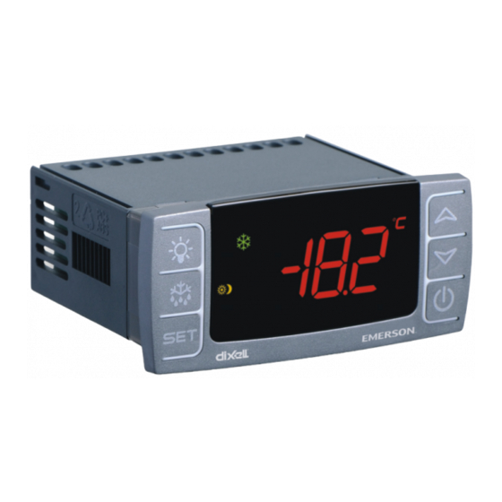
1.1. General Warning 2.1. General Description Please read the following safety precautions and The XR75CX-Case Display (32 mm x 74 mm) is warnings before using this manual: a microprocessor based controller, suitable for appli- cations on medium or low temperature ventilated re- frigeration units. -
Page 8: X-Rep Output (Optional)
XR75 Kit, Case Display - 230 VAC RED 818-6041 XR75 Kit, Case Display - 110 VAC BLUE 818-6050 XR75 Kit, Case Display - 230 VAC BLUE 818-6051 XR75 Manual 026-1217 Table 2-2 - Product Ordering Code 2 • XR75CX-CD I&O Manual 026-1217 Rev 0 08-NOV-2011... -
Page 9: Case Display Outputs
Case Display Outputs On-Board Relay Outputs The XR75CX-CD has 4 on-board relays that may be used as satellite outputs by other E2 applications. Wire the outputs to the two-wire terminals on the right side of the control unit. For loads greater than 3A, use the outputs to energize external relays. -
Page 10: E2 Setup
XR75CX-CD you want to associate. For 4.1. Configuring the example, if you want to associate XR75CX-CD #7 with this circuit, select CL CD007 from the Look-Up Table. XR75CX-CD Through E2... -
Page 11: Operation
5.1. Output Relay Control Circuit application in E2, a “Case Temp Hi Limit Exceeded” or “Case Temp Lo Limit Exceeded” The 4 on-board relays on the XR75CX-CD are con- alarm that occurs for the XR75CX-CD’s associated trolled by the associated XR75CX-CD application in case will cause the main module and remote display’s... -
Page 12: Front Panel Commands
Switches the device ON and OFF To enter programming mode Returns to room temperature display Table 6-1 - XR75CX-CD Front Panel Keys and Functions 6 • XR75CX-CD I&O Manual 026-1217 Rev 0 08-NOV-2011... -
Page 13: Main Functions
19200. 6. Press SET to save. NOTE: The set value is stored even when the time-out expires and ends the procedure. The E2 will override values set at the XR75CX Case Display device. 7.2. How to Assign a MODBUS Address 1. -
Page 14: Parameters
10 to 255 sec Firmware Release read only Map code read only Pr2 access disabling after the first minute 0=no 1=yes .dsPR2 Lock keyboard enabling 0=no 1=yes .eLock Table 8-1 - List of Parameters 8 • XR75CX-CD I&O Manual 026-1217 Rev 0 08-NOV-2011... -
Page 15: Digital Inputs
9.1. ON - OFF Function Switches the controller ON and OFF. 9.2. Digital Inputs Polarity Figure 10-1 - Installation and Mounting of XR75CX-CD The digital input polarity depends on the i1P and i2P parameters. The XR75CX-CD controller should be mounted •... -
Page 16: Electrical Connections
(where most ice is formed) and far from heaters or from the warmest place during defrost to prevent premature defrost termination. 10 • XR75CX-CD I&O Manual 026-1217 Rev 0 08-NOV-2011... -
Page 17: Specifications
Operating: 0 to 55°C Temperatures Storage: -30 to 85°C 20 to 85% (no condensing) Relative Humidity 0.1°C or 1°C or 1°F (selectable) Resolution ±0.7°C ±1 digit Accuracy (ambient temperature 25°C) Table 13-1 - XR75CX-CD Specifications Probe Connection Specifications • 11... -
Page 18: Connections
14 Connections Figure 14-1 - XR75CX-CD Connections NOTES: 120V or 230V depending on the model. The Hot Key function is not used on the XR75CX-CD. 12 • XR75CX-CD I&O Manual 026-1217 Rev 0 08-NOV-2011... -
Page 19: E2 Modbus Network Wiring
18 terminal. • Terminate the end of the MODBUS network at the last XR75CX-CD device on the daisy chain with the MODBUS termination block (P/N 535-2711), or by connecting a 150 ohm resistor between the MODBUS +/- terminals. -
Page 20: Ect Modbus Networking To E2S
Figure 16-1 - Location of E2 Com Ports (E2 versions 3.xx and Below) Connecting a XR75CX-CD controller to an E2 re- quires the E2 to be version 3.02 or above. Contact Re- tail Solutions for upgrade information if the controller Figure 16-2 - Location of E2 COM Ports - E2 PIB Board (E2 is a version before 3.02. -
Page 21: E2 Setup Of Devices
16.3.2.Add and Connect the Device Figure 16-3 - MODBUS Networking To enable communications between E2 and the XR75CX-CD units, the devices must be added and addressed in E2. 16.3. E2 Setup of Devices Log in to the E2 with Level 4 access. - Page 22 . In the list of MODBUS devices, choose the address number corresponding to the XR75CX-CD address set up through the front display, and press to select it. A window will open where you can specify the address of the controller.
- Page 23 120W±50W Nominal Impedance 16.5. MODBUS Termination Blocks Because the XR75CX-CD device has no on-board means of termination, use the MODBUS termination block (P/N 535-2711) for termination that can be wired to the end of the cable segment using the three- pin connector.
- Page 25 Computer Process Controls, Inc. does not assume responsibility for the selection, use or maintenance of any product. Responsibility for proper selection, use and main- tenance of any Computer Process Controls, Inc. product remains solely with the purchaser and end-user. 026-1217 08-NOV-2011 Emerson is a trademark of Emerson Electric Co. ©2011 Computer Process Controls, Inc. All rights reserved. Printed in the USA.