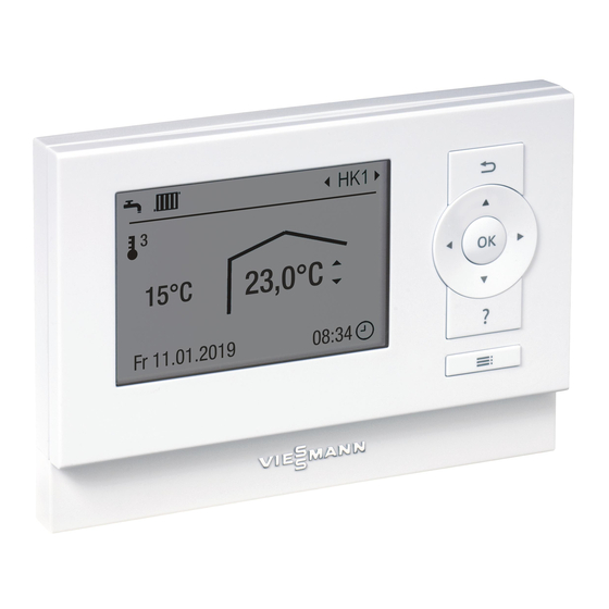
Viessmann VITOTROL 200-E Installation And Service Instructions Manual
Remote control for up to 4 heating circuits
Hide thumbs
Also See for VITOTROL 200-E:
- Installation and service instructions manual (20 pages) ,
- Operating instructions manual (36 pages) ,
- Operating instructions manual (24 pages)
Table of Contents
Advertisement
Quick Links
Advertisement
Table of Contents

Related Manuals for Viessmann VITOTROL 200-E


Summary of Contents for Viessmann VITOTROL 200-E
- Page 1 Installation and Service Instructions for use by heating contractor Vitotrol 200-E Remote Control for up to 4 heating circuits VITOTROL 200-E Product may not be exactly as shown IMPORTANT Read and save these instructions for future reference. Please file in Service Binder...
-
Page 2: Safety, Installation And Warranty Requirements
Information contained in this and installation of carbon monoxide detectors. Follow the related product documentation must Viessmann maintenance schedule of the boiler contained be read and followed. Failure to do in this manual. so renders the warranty null and void. -
Page 3: Product Information
Intended use Install and operate the appliance as intended, in con- junction with the electronic control units and controllers for the Viessmann boilers designed for this system. Also take account of the relevant installation, service and operating instructions. In particular, observe the current and voltage specifications for connections and hook-ups. -
Page 4: Table Of Contents
General Product Information ........... 3 Installation Place of Installation ........... 5 Fitting and Connecting the Vitotrol 200-E ..... 5 Connecting Several Remote Controls ......6 Installing the Programming Unit ........7 Removing the Programming Unit (if required) ....7 Commissioning Configuring the Remote Control ........ -
Page 5: Place Of Installation
– Not above radiators temperature sensor. – Not near heat sources (direct sunlight, fireplace, TV set, etc.) Fitting and Connecting the Vitotrol 200-E Note: Electronic assemblies can be damaged by electrostatic discharge. Prior to commencing any work, touch earthed objects such as heating or water pipes to discharge static loads. -
Page 6: Connecting Several Remote Controls
Installation Vitotrol 200-E, Installation and Service Connecting Several Remote Controls Two Vitotrol 200-E can be connected to the same Version 1 control unit. Total length of all PlusBus cables max. 150 ft. (50 m). Legend A To the control unit... -
Page 7: Installing The Programming Unit
Installation Installing the Programming Unit Note: The remote control is supplied with power by the control unit. IMPORTANT Do not insert batteries into the programming unit. 1. Install wiring cover plate at the base of the wall mounting plate. 2. Hook the right side of the interface into the wall mounting plate. -
Page 8: Configuring The Remote Control
See chapter “Configuration following replacement of the remote control”. Subscriber number shown Subscriber number to be If there is already a Vitotrol 200-E connected to the at the control unit set at the remote control heating system and an additional Vitotrol 200-E is being fitted: See chapter “Configuration of an... -
Page 9: Service Indication
Troubleshooting Vitotrol 200-E, Installation and Service Service Indication If the heating system is due for a service, the symbol flashes on the display and “Service” is shown. Call up the submenu with the OK key to acknowledge all current service messages. -
Page 10: Specifications
Specification Vitotrol 200-E, Installation and Service Specifications Power supply Via PlusBus Voltage Current 25 mA Permissible ambient temperature Operation 32 to +104°F (0 to +40°C) Storage and transport -4 to 150°F (-20 to +65°C) 5 to 95%, noncondensing... - Page 11 Vitotrol 200-E, Installation and Service...
- Page 12 Vitotrol 200-E, Installation and Service Scan for digital copy of this document...