
Related Manuals for Asus Aaeon UP Xtreme i11 EDGE


Summary of Contents for Asus Aaeon UP Xtreme i11 EDGE
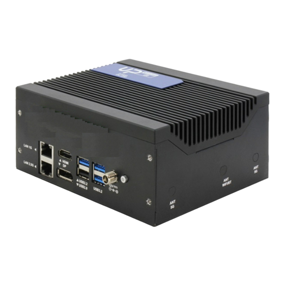
- Page 1 UP Xtreme i11 EDGE Maker Board System UPX-EDGE-TGL01 User’s Manual 2 Edition Last Updated: October 13, 2022...
- Page 2 Copyright Notice This document is copyrighted, 2022. All rights are reserved. The original manufacturer reserves the right to make improvements to the products described in this manual at any time without notice. No part of this manual may be reproduced, copied, translated, or transmitted in any form or by any means without the prior written permission of the original manufacturer.
- Page 3 Acknowledgements All other product names or trademarks are properties of their respective owners. Microsoft Windows and Windows 10 are registered trademarks of Microsoft ⚫ Corp. Intel® and Celeron® are registered trademarks of Intel Corporation ⚫ Intel Core™ is a registered trademark of Intel Corporation ⚫...
- Page 4 Packing List Before setting up your product, please make sure the following items have been shipped: Item Quantity UP Xtreme i11 EDGE System If any of these items are missing or damaged, please contact your distributor or sales representative immediately. Preface...
- Page 5 About this Document This User’s Manual contains all the essential information, such as detailed descriptions, and explanations on the product’s hardware and software features (if any), its specifications, dimensions, jumper/connector settings and definitions, and driver installation instructions (if any) to facilitate users in setting up their product Users may refer to the product page at AAEON.com for the latest version of this document.
- Page 6 Safety Precautions Please read the following safety instructions carefully. It is advised to keep a printed copy of this manual in an easy to access location for reference. All cautions and warnings on the device should be noted. Make sure the power source matches the power rating of the device. Position the power cord so that people cannot step on it.
- Page 7 If any of the following situations arises, please the contact our service personnel: Damaged power cord or plug Liquid intrusion to the device iii. Exposure to moisture Device is not working as expected or in a manner as described in this manual The device is dropped or damaged Any obvious signs of damage displayed on the device...
- Page 8 FCC Statement This device complies with Part 15 FCC Rules. Operation is subject to the following two conditions: (1) this device may not cause harmful interference, and (2) this device must accept any interference received including interference that may cause undesired operation.
- Page 9 China RoHS Requirements (CN) 产品中有毒有害物质或元素名称及含量 AAEON System QO4-381 Rev.A0 有毒有害物质或元素 部件名称 铅 汞 镉 六价铬 多溴联 多溴二苯 苯(PBB) 醚(PBDE) (Pb) (Hg) (Cd) (Cr(VI)) 印刷电路板 × ○ ○ ○ ○ ○ 及其电子组件 外部信号 × ○ ○ ○ ○ ○ 连接器及线材 外壳 ○...
- Page 10 China RoHS Requirement (EN) Hazardous and Toxic Materials List AAEON System QO4-381 Rev.A0 Hazardous or Toxic Materials or Elements Component Name PCB and Components Wires & Connectors for Ext.Connections Chassis CPU & RAM HDD Drive LCD Module Optical Drive Touch Control Module Battery This form is prepared in compliance with the provisions of SJ/T 11364.
-
Page 11: Table Of Contents
Table of Contents Chapter 1 - Product Specifications ..................1 Specifications ......................2 Chapter 2 – Hardware Information ..................4 Dimensions ......................... 5 Jumpers and Connectors ..................8 List of Jumpers and Connectors ................11 2.3.1 Power Button (SW1) .................... 12 2.3.2 RTC (CN1) ...................... - Page 12 2.3.21 ATX Power (CN31) ....................28 2.3.22 SATA Power (CN32) ..................29 2.3.23 Audio Jack (CN33) ..................... 29 2.3.24 Fan Connector (J1) ..................... 30 2.3.25 AT/ATX Mode Jumper (JP1) ................30 2.3.26 GPIO Terminal Block................... 31 2.4 Hardware Assembly ......................32 2.4.1 Wi Fi Module (M.2 2230 E-Key Slot) Installation .........
-
Page 13: Chapter 1 - Product Specifications
Chapter 1 Chapter 1 - Product Specifications... -
Page 14: Specifications
Specifications System 11th Gen Intel® Core™ Processor SoC Core™ i7-1185GRE Core™ i5-1145GRE Core™ i3-1115GRE Celeron® 6305E Memory DDR4 SO-DIMM Slot x 2 (up to 64GB 3200MHz) Graphics Intel® Iris® Xe Graphics Storage SATA Connector x 1 (with Power) M.2 2280 M-Key NVMe (PCIe [x2]) Ethernet Intel®... - Page 15 Power 12V DC-In (lockable plug)/ Phoenix Connector (Optional) USB 3.2 Gen 2 x 3 USB 2.0 x 1 (Type A) USB4 Type C x 1 Display Port HDMI 2.0 x 1 DP 1.4 x 1 eDP x 1, 4K at 60Hz Panel Ethernet Intel®...
-
Page 16: Chapter 2 - Hardware Information
Chapter 2 – Hardware Information Chapter 2... -
Page 17: Dimensions
Dimensions System Dimensions Chapter 2 – Hardware Information... - Page 18 System Dimensions with fan Chapter 2 – Hardware Information...
- Page 19 Board Dimensions Chapter 2 – Hardware Information...
-
Page 20: Jumpers And Connectors
Jumpers and Connectors UPX-EDGE-TGL01 System: Chapter 2 – Hardware Information... - Page 21 Board Top: Chapter 2 – Hardware Information...
- Page 22 Board Bottom: Chapter 2 – Hardware Information...
-
Page 23: List Of Jumpers And Connectors
List of Jumpers and Connectors Please refer to the table below for all of the board’s jumpers and connectors that you can configure for your application Label Function Power Button HDMI/DP Dual Port eDP Connector SATA Connector USB Type A Dual Port USB Type A Dual Port CN10 USB Type C... -
Page 24: Power Button (Sw1)
Label Function Terminal Block GPIO 2.3.1 Power Button (SW1) Signal Signal PWR_SW# PWR_SW# SW1_LED_P SW1_LED_N 2.3.2 RTC (CN1) Signal RTC_VCC Chapter 2 – Hardware Information... -
Page 25: Hdmi/ Dp Dual Port (Cn2)
2.3.3 HDMI/ DP Dual Port (CN2) Signal Signal Signal DP_TXP0 DP_TXN0 DP_TXP1 DP_TXN1 DP_TXP2 DP_TXN2 DP_CLK+ DP_CLK- CONFIG1 CONFIG2 DP_AUX_P DP_AUX_N DP_HPD 3.3V HDMI_TXP0 HDMI_TXN0 HDMI_TXP1 HDMI_TXN1 HDMI_TXP2 HDMI_TXN2 HDMI_CLK+ HDMI_CLK- HDMI_CEC DDC_CLK DDC_DATA HDMI_HPD Chapter 2 – Hardware Information... -
Page 26: Edp (Cn3)
2.3.4 eDP (CN3) Signal Signal +VDD_3V3 +VDD_3V3 EDP_TXN2 EDP_TXP2 EDP_TXN1 EDP_TXP1 EDP_TXN0 EDP_TXP0 EDP_TXN3 EDP_TXP3 EDP_AUXN EDP_AUXP BKLT_CTRL BKLT_EN EDP_HPD +12V +12V +12V +12V Chapter 2 – Hardware Information... -
Page 27: Sata Connector (Cn4)
2.3.5 SATA Connector (CN4) Signal Signal SATA_TXP0 SATA_TXN0 SATA_RXN0 SATA_RXP0 2.3.6 USB Type A Dual Port (CN8) Signal Signal Signal USB2_D1- USB2_D1+ USB3_RX1- USB3_RX1+ USB3_TX1- USB3_TX1+ USB2_D2- USB2_D2+ Chapter 2 – Hardware Information... -
Page 28: Usb Type A Dual Port (Cn9)
2.3.7 USB Type A Dual Port (CN9) Signal Signal Signal USB2_D3- USB2_D3+ USB3_RX3- USB3_RX3+ USB3_TX3- USB3_TX3+ USB2_D4- USB2_D4+ USB3_RX4- USB3_RX4+ USB3_TX4- USB3_TX4+ 2.3.8 USB Type C (CN10) Signal Signal Signal SSTXP1 SSTXN1 SBU1 SSRXN2 SSRXP2 SSTXP2 SSTXN2 Chapter 2 – Hardware Information... -
Page 29: Usb 2.0/Uart 1X10P Wafer (Cn11)
Signal Signal Signal SBU2 SSRXN1 SSRXP1 2.3.9 USB 2.0/UART 1x10P Wafer (CN11) Signal Signal Signal USB2_D5- USB2_D5+ USB2_D6- USB2_D6+ UART_RX UART_TX Chapter 2 – Hardware Information... -
Page 30: 2230 E-Key Slot (Cn12)
2.3.10 M.2 2230 E-Key Slot (CN12) Signal Signal Signal +3.3V USB2_D10+ +3.3V USB2_D10- CNV_WR_LANE1_ CNV_WR_LANE1_ CNV_RF_RST# CNV_WR_LANE0_ CNV_CLKREQ_R CNV_WR_LANE0_ CNV_WR_CLK_DN CNV_RGI_RSP_R CNV_WR_CLK_DP CNV_RGI_DT CNV_RGI_RSP PCIE9_TXP CNV_BRI_DT PCIE9_TXN PCIE9_RXP PCIE9_RXN PCIE5_CLKP PCIE5_CLKN SUS_CLK WIFI_RST# PCIE_CLKREQ# BT_EN PCIE_WAKE# WIFI_EN Chapter 2 – Hardware Information... -
Page 31: 2280 M-Key Slot (Cn13)
Signal Signal Signal CNV_WT_LANE1_ CNV_WT_LANE1_ CNV_WT_LANE0_ CNV_WT_LANE0_ CNV_WT_CLK_DN +3.3V CNV_WT_CLK_DP +3.3V 2.3.11 M.2 2280 M-Key Slot (CN13) Signal Signal Signal +3.3V +3.3V +3.3V +3.3V +3.3V +3.3V PCIE1_RXN PCIE1_RXP Chapter 2 – Hardware Information... - Page 32 Signal Signal Signal PCIE1_TXN PCIE1_TXP SSD_DEV_SLP SMB_CLK_1V8 PCIE0_RXN SMB_DATA_1V8 PCIE0_RXP PCIE0_TXN PCIE0_TXP PLT_RST# PCIE_CLKREQ# PCIE3_CLKN PCIE_WAKE# PCIE3_CLKP +3.3V +3.3V +3.3V Chapter 2 – Hardware Information...
-
Page 33: 3052 B-Key Slot (Cn14)
2.3.12 M.2 3052 B-Key Slot (CN14) Signal Signal Signal +3.3V FULL_CARD_ +3.3V POWER_OFF# USB2_D8+ W_DISABLE#1 USB2_D8- USB3_RX- UIM_RST USB3_RX+ UIM_CLK UIM_DAT USB3_TX- UIM_PWR USB3_TX+ PCIE10_RXN PCIE10_RXP PCIE10_TXN PCIE10_TXP PLT_RST#(3.3V) PCIE_CLKREQ# PCIE4_CLKN PCIE_WAKE# PCIE4_CLKP Chapter 2 – Hardware Information... -
Page 34: Lan Dual Port (Cn15)
Signal Signal Signal PLT_RST#(1.8V) +3.3V +3.3V +3.3V 2.3.13 LAN Dual Port (CN15) Signal Signal Signal LAN1_MDI0+ LAN1_MDI0- LAN1_MDI1+ LAN1_MDI1- LAN1_MDI2+ LAN1_MDI2- LAN1_MDI3+ LAN1_MDI3- R10A GND LAN1_ACTLED- LAN1_ACTLED+ LAN1_LINK100# LAN1_LINK1000# LAN2_MDI0+ LAN2_MDI0- LAN2_MDI1+ LAN2_MDI1- LAN2_MDI2+ LAN2_MDI2- LAN2_MDI3+ LAN2_MDI3- R10B LAN2_ACTLED- LAN2_ACTLED+ LAN2_LINK100# LAN2_LINK1000# Chapter 2 –... -
Page 35: Pci Express Slot (Cn18)
2.3.14 PCI Express Slot (CN18) Signal Signal Signal +12V +12V +3.3V +3.3V PLT_RST# PCIE0_CLKP PCIE0_CLKN PCIE4_P0_RXP PCIE4_P0_RXN PCIE4_P1_RXP PCIE4_P1_RXN PCIE4_P2_RXP PCIE4_P2_RXN PCIE4_P3_RXP PCIE4_P3_RXN +12V +12V +12V SMB_CLK SMB_DATA +3.3V +V3.3A PCIE_WAKE# PCIE4_P0_TXP PCIE4_P0_TXN PCIE4_P1_TXP PCIE4_P1_TXN PCIE4_P2_TXP PCIE4_P2_TXN PCIE4_P3_TXP PCIE4_P3_TXN Chapter 2 – Hardware Information... -
Page 36: 40-Pin Hat Connector (Cn19)
Signal Signal Signal 2.3.15 40-Pin HAT Connector (CN19) Signal Signal +3.3V I2C1_DAT / GPIO1 I2C1_CLK / GPIO2 ANALOG_DATA / GPIO3 UART_TX / GPIO16 UART_RX / GPIO17 GPIO4 I2S_BCLK / GPIO18 GPIO5 GPIO6 GPIO19 +3.3V GPIO20 SPI_MOSI / GPIO7 SPI_MISO / GPIO8 GPIO21 SPI_CLK / GPIO9 SPI_CS0 / GPIO22... -
Page 37: Cpld And Bios Update (Cn20)
Signal Signal GPIO15 I2S_SDI / GPIO27 I2S_SDO / GPIO28 2.3.16 CPLD and BIOS Update (CN20) Signal Signal JTAG_TCK JTAG_TDO 1.8V JTAG_TMS SPI_CS SPI_CLK SPI_MISO JTAG_TDI SPI_MOSI SPI_HOLD 2.3.17 DC Jack (CN21) Signal DC_IN Chapter 2 – Hardware Information... -
Page 38: Front Panel (Cn22)
2.3.18 Front Panel (CN22) Signal Signal RESET POWER S/W +3.3V 2.3.19 DC Terminal Block (CN23) Signal DC_IN Chapter 2 – Hardware Information... -
Page 39: Com3, Com4 Rs232/ 422/ 485 (Cn28/Cn29)
2.3.20 COM3, COM4 RS232/ 422/ 485 (CN28/CN29) Signal Signal DCD/ RS422TX-/ S485- RX/ RS422TX+/ RS485+ TX/ RS422RX+ DTR/ RS422RX- 2.3.20.1 COM3 1x10P Wafer RS232/ 422/ 485 (CN28) Signal Description Signal Description DCD / RS422TX- / S485- RX / RS422TX+ / RS485+ TX / RS422RX+ DTR / RS422RX- Chapter 2 –... -
Page 40: Com4 1X10P Wafer Rs232/422/485 (Cn29)
2.3.20.2 COM4 1x10P Wafer RS232/422/485 (CN29) Signal Signal DCD / RS422TX- / S485- RX / RS422TX+ / RS485+ TX / RS422RX+ DTR / RS422RX- 2.3.21 ATX Power (CN31) Signal Signal 12V OUT 12V OUT Chapter 2 – Hardware Information... -
Page 41: Sata Power (Cn32)
2.3.22 SATA Power (CN32) Signal 2.3.23 Audio Jack (CN33) Signal Signal MIC_LR LOUT_R AUDIO-JD LOUT_L Chapter 2 – Hardware Information... -
Page 42: Fan Connector (J1)
2.3.24 Fan Connector (J1) Signal Signal TACH 2.3.25 AT/ATX Mode Jumper (JP1) Signal ATX_MODE PWRBTN AT_MODE ATX Mode (Default) AT Mode Chapter 2 – Hardware Information... -
Page 43: Gpio Terminal Block
2.3.26 GPIO Terminal Block Signal Signal PIN1 (3.3V) PIN2 (5V) PIN3 (I2C_SDA) PIN5 (I2C_SCL) PIN6 (GND) PIN9 (GND) PIN12 (GPIO) PIN13 (GPIO) PIN15 (GPIO) PIN16 (GPIO) PIN18 (GPIO) PIN19 (GPIO) PIN21 (GPIO) PIN22 (GPIO) PIN32 (PWM0) PIN33 (PWM1) Note: PWM function (PIN32, PIN33) only supported with UP Framework SDK Chapter 2 –... -
Page 44: 2.4 Hardware Assembly
2.4 Hardware Assembly This section details the steps needed to install various hardware components for the UP Xtreme i11 Edge. It is recommended that you read through each step before beginning installation and to make sure you have all necessary tools and components. 2.4.1 Wi Fi Module (M.2 2230 E-Key Slot) Installation For this process you will need a Phillips head screwdriver. - Page 45 Step 2: Remove the screw and assemble the Wi-Fi module of the 2230 card, then secure the screw to hold the module in place. Chapter 2 – Hardware Information...
- Page 46 Step 3: Remove the metal cover on the ANT Wi-Fi/BT antenna hole (1 hole located on the left and right sides of the system). Chapter 2 – Hardware Information...
- Page 47 Step 4: Install the two antenna cables, and tighten the outer nut and washer, then install the antenna IPEX connector on the Wi-Fi card and affix it with glue. Please use hot‑melt adhesive with UL94 V-0 certification. Chapter 2 – Hardware Information...
- Page 48 Step 5: Lock the 4 screws to the top plate in the following order. Warning: This SOP is referring to assembly steps, thermal solutions for different • modules are not considered. Please check the block diagram in the product datasheet for module •...
-
Page 49: Pcie Module (M.2 2280 M-Key Slot) Installation
2.4.2 PCIe Module (M.2 2280 M-Key Slot) Installation For this process you will need a Phillips head screwdriver. Step 1: Remove the screws on the bottom plate. Chapter 2 – Hardware Information... - Page 50 Step 2: Remove the outer nut and washer on Power Jack and the 4 screws on the rear cover. Chapter 2 – Hardware Information...
- Page 51 Step 3: Remove the PCBA screws 4pcs and cables from wafers. Chapter 2 – Hardware Information...
- Page 52 Step 4: Put bottom board up and remove the PCB screw then install the PCIe module. Chapter 2 – Hardware Information...
- Page 53 Step 5: If the thermal pad is damaged, it needs to be replaced with new one. Chapter 2 – Hardware Information...
-
Page 54: 2.4.2.1 Reassembling The System
2.4.2.1 Reassembling the System Follow the below steps to reassemble the whole system. Step 1: Assemble the GPIO Cable. To do this, reverse the board. Please see correct placement below figure and ensure GPIO Cable is between iron pillars. Chapter 2 – Hardware Information... - Page 55 Step 2: Assemble COM 4 and COM 3 Cables. COM 4 COM 3 Step 3: To reassemble the system, follow steps 1-3 in reverse order, like so: Step 3 → Step 2 → Step 1 → Warning: This SOP is referring to assembly steps, thermal solutions for different modules •...
-
Page 56: Module (M.2 3052 B-Key Slot) Installation
2.4.3 5G Module (M.2 3052 B-Key Slot) Installation For this process you will need a Phillips head screwdriver. Step 1: Remove the screws on the bottom plate. Chapter 2 – Hardware Information... - Page 57 Step 2: Remove the screw and pillar and assemble the 5G module of the 3052 card, then secure the screw to hold the module in place. Chapter 2 – Hardware Information...
- Page 58 Step 3: Remove the metal cover on the ANT 5G antenna hole (holes located on the left and right sides of the system). Chapter 2 – Hardware Information...
- Page 59 Step 4: Install the 4 antenna cables, and tighten the outer nut and washer, then install the antenna IPEX connector on the 5G card and affix it with glue. Please use hot‑melt adhesive with UL94 V-0 certification. Chapter 2 – Hardware Information...
- Page 60 Step 5: Lock the 4 screws to the top plate in the following order. Warning: This SOP is referring to assembly steps, thermal solutions for different • modules are not considered. Please check the block diagram in the product datasheet for module •...
-
Page 61: 2.5" Sata Drive Installation
2.4.4 2.5” SATA Drive Installation For this process you will need a Phillips head screwdriver. Step 1: Remove the screws on the bottom plate. Chapter 2 – Hardware Information... - Page 62 Step 2: Assembling the 2.5" HDD/SSD Cable. Place the 2.5" HDD/SSD Cable below. Lock the screws in the order shown, then plug the 2.5" HDD/SSD cable and affix it with glue. Please use hot‑melt adhesive with UL94 V-0 certification. Chapter 2 – Hardware Information...
- Page 63 Step 3: Plug the cable into the SATA, then connect the SATA power and affix it with glue. Please use hot‑melt adhesive with UL94 V-0 certification. Chapter 2 – Hardware Information...
- Page 64 Step 4: Lock the 4 screws to the top plate in the following order. Warning: This SOP is referring to assembly steps, thermal solutions for different • modules are not considered. Please check the block diagram in the product datasheet for module •...
-
Page 65: Vesa Mount Installation
2.4.5 VESA Mount Installation For this process you will need a Phillips head screwdriver. Step 1: Remove screws on the bottom plate. Step 2: Pick up VESA Bracket. Chapter 2 – Hardware Information... - Page 66 Step 3: Use 4 screws (refer to step 1) to lock VESA Bracket. Chapter 2 – Hardware Information...
-
Page 67: Chapter 3 - Software Installation
Chapter 3 Chapter 3 – Software Installation... -
Page 68: Linux Setup
Linux Setup UP Xtreme I11 EDGE supports Linux operating systems (see Chapter 1 for specifications). For instructions on how to install a Linux OS onto your UP Xtreme I11 EDGE, you can find several guides and tutorials in the wiki section of the UP Board website at https://up-board.org for both installing supported distributions as well as... -
Page 69: Dummy Driver Installation
Dummy Driver Installation The following instructions detail how to install the dummy driver for UPX-EDGE-TGL01. Step 1 – Open Device Manager in Windows by searching for the app in the Start Menu. Chapter 3 – Software Installation... - Page 70 Step 2 – Under “Other devices” look for Intel High Definition Audio. Right click on the device and select “Update driver”. Step 3 – Select “Browse my computer for drivers” Chapter 3 – Software Installation...
- Page 71 Step 4 – Click “Browse…” and select the folder where you saved the dummy driver software. Chapter 3 – Software Installation...
- Page 72 Step 5 – Repeat for Unknown device Chapter 3 – Software Installation...
-
Page 73: Appendix A - Up Framework Sdk Installation
Appendix A Appendix A – UP Framework SDK Installation... -
Page 74: Introduction
Introduction This section provides instructions for the installation of the UP Framework SDK. Instructions are provided for Windows 10 and Windows IoT Core. You can download the latest version of UP Framework SDK from the UP community: https://downloads.up-community.org/download/up-sdk-for-windows-10-and-windows-iot/ Installation for Windows 10 Step 1 Locate the downloaded file UpFrameworkSetup.msi and run the installer. - Page 75 Step 2 Select the installation folder. Default destination path is C:\Program Files(x86)\AAEON\ You may also choose to install the UP Framework SDK for all users or only the current user. Press “Next” to continue installation. Step 3 Press “Next” to confirm the installation. Appendix A –...
- Page 76 Step 4 Press “Close” to exit once setup is complete. Appendix A – UP Framework SDK Installation...
-
Page 77: Installation For Windows Iot Core
Installation for Windows IoT Core Before you begin, make sure you have downloaded and installed the latest version of the Windows IoT Core image from the UP community. Installation requires using a connected PC with the UP Framework SDK software downloaded and saved. - Page 78 Step 2 Download the UP Framework SDK to your PC and unzip the files. Open PowerShell as an Administrator. Enter the command RemoteInstallation.ps1 to install the UP Framework SDK. Enter the IP address of the UP IoT Core device when prompted. Appendix A –...
-
Page 79: Appendix B - Cables And Connectors
Appendix B Appendix B – Cables and Connectors... -
Page 80: Cables And Connectors
Cables and Connectors This table provides detailed information about the cables and connectors used by the UP Xtreme EDGE i11 (UPX-EDGE-TGL01). If you have any questions about the configuration of your board, please contact your AAEON sales representative. Mating Mating Cable Label Connector PN Description... - Page 81 Mating Mating Cable Label Connector PN Description Cable PN Description Cable.40P.Pitch=3.81m m.16P-to-40P CN19 165302020L 40-pin HAT Connector 170X000277 header.300mm.FLYING WAY.FWAA-1418 DC Power Jack.3P (DC CN21 165250320K 12V) Wafer Box.6P. Front CN22 1655906033 Panel (Power on + Reset) (TF) COM Cable.D-SUB 9P(M).10P.1.0mm Wafer Box.10P.