Table of Contents
Advertisement
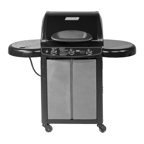
Gas Barbecue
Use, Care & Assembly Manual
With Grill Lighting Instructions
5100 LP Gas Series
5110 Natural Gas Series
ASSEMBLER/INSTALLER:
Leave these instructions with the consumer.
CONSUMER/USER:
Read all these instructions and keep them in a safe place for future reference.
For Outdoor Use Only
www.coleman.com
I I M M P P O O R R T T A A N N T T
Read this manual carefully before assembling,
using or servicing this grill. Keep this manual for
future reference. If you have questions about
assembly, operation, servicing or repair of this
stove, please call Coleman at 1-800-835-3278
C E R T I F I E D
®
®
or TDD: 316-832-8707. In Canada call
1-800-387-6161.
Advertisement
Table of Contents

Related Manuals for Coleman 5100 LP Gas Series


Summary of Contents for Coleman 5100 LP Gas Series
- Page 1 Keep this manual for future reference. If you have questions about assembly, operation, servicing or repair of this stove, please call Coleman at 1-800-835-3278 C E R T I F I E D ® ®...
-
Page 2: Table Of Contents
• NEVER place more than 15 pounds on a side table or a side burner. DO NOT lean on grill. (Fig. 5) • NEVER use charcoal briquettes or lighter fluid in a gas grill. (Fig. 6) • Grill is hot when in use; to avoid burns, DO NOT touch any hot grill surface. -
Page 3: General Installation
General Safety Information cont. General Installation • Installation must conform with local codes or, in the absence of local codes, with either the National Fuel Gas Code, ANSI Z223.1 (USA), CAN/CGA-B149.1, Natural Gas Installation Code or CAN/CGA-B149.2, Propane Installation Code (Canada). To check local codes, see your local L.P. -
Page 4: Electrical Attachments
L.P. gas is heavier than air and tends to collect in low areas. It is important that there are no leaking connections on your gas grill that could cause a fire or explosion (see “LEAK TESTING”, Pg. 26). -
Page 5: L.p. Gas Cylinder
Do not use another hose and regulator assembly other than the one supplied with the grill or a Coleman replacement pressure regulator assembly. The pressure regulator and hose assembly provided is factory set at an outlet pressure of 11 inches water column (1/2 psi). -
Page 6: Filling And Purging Type 1 L.p. Gas Cylinders
Transporting the Cylinder WARNING Handle a full cylinder with care. Gas is under high pressure. DANGER • NEVER store a spare L.P. gas supply cylinder under the grill body or inside grill enclosure or in the vicinity of any heat producing appliance. (Fig. 12) •... -
Page 7: Assembly/Set Up
Assembly/Set up Remove components from package. Left Side Burner Table Rear Trim Plate Warming Rack Grease Pan Grease 9-Volt Battery Left Panel Left Door Side Burner Knob Left Side Burner Electrode Rear Support Top Panel Cylinder Retaining Bolt Grease Support Electrode Module Base Door... - Page 8 NOTE: Use a large piece of cardboard or a ground cloth to protect the painted finish on the grill. Step Right Panel Hardware shown actual size (TN) M6 x 15mm Screw (10) Qty. Base Left Panel 1-A. Arrange the two panels and the base on the ground as shown. LOOSELY assemble the Right Panel and the Left Panel to the Grill Base using one screw (TN) in each top corner.
- Page 9 Carefully turn the assembly up-side-down to perform Step 2. This will give easy Step access to assemble the parts in Step 2. Hardware shown actual size M6 x 15mm Screw Base (up-side-down) 2-A. Carefully turn the grill Up-Side-Down. 2-A. Carefully turn the grill Up-Side-Down. TN (x4) 2-B.
- Page 10 NOTE: Use a ground cloth to protect the paint finish during this step. Step 2-A. Carefully turn the grill Up-Side-Down. Locking Casters 3-A. Check that all fasteners are tightened before turning the grill Right-Side-Up. Carefully turn the grill Right-Side-Up. Engage the Locking Casters to prevent movement during the rest of the assembly process.
- Page 11 Assemble the Top Panel. Assemble the Rear Support. Step Hardware shown actual size (TN) M6 x 15mm Screw (16) Qty. 5-A. Assemble the Top Panel to the Left and Right Side Panels with eight Screws (TN). 5-B. Assemble the Rear Support to the Left and Right Side Panels with eight Screws (TN).
- Page 12 Step Hardware shown actual size (CX) M6 x 20mm Screw (5) Qty. FIREBOX 7-A. Lay the Firebox on it’s backside with lid closed . This will allow easy access to the fastener locations. Assemble the Right Side Table to the Firebox with five Screws (CX) and one Locking Hex Nut (UO).
- Page 13 Assemble Left Side Burner Assembly to the Firebox. Step Hardware shown actual size (CX) M6 x 20mm Screw (5) Qty. Left Side Burner Table 8-A. Assemble the Left Side Burner Table to the Firebox with five Screws (CX) and one Locking Hex Nut (UO). Place the Locking Hex Nut in the center position as shown in 8-C.
- Page 14 Assemble Firebox to the Grill Cart. HINT: A second person is Step helpful when aligning the Firebox to the Grill Cart. FIREBOX GRILL CART 9-A. Carefully place the Firebox onto the Cart Assembly. Take care to not damage the fuel hoses. They must be routed through the large hole in the top panel.
- Page 15 Fasten the Firebox to the Grill Cart. Step 10-A TN (x3) 10-A. LOOSELY fasten the right side of the Firebox to the Grill Cart with three Screws (TN), two Flat Washers (DY) and two Locking Hex Nuts (UO). NOTE: You will tighten these screws LATER (after Step 10-B), after the left side of the Firebox is attached to the Grill Cart (this helps with alignment).
- Page 16 Fasten the Rear Trim Plate to the Grill Cart. Step Hardware shown actual size (VP) Self Tapping Screw (2) Qty. 11-A 11-A. Fasten the Rear Trim Plate to the Firebox with two Screws (VP). Tighten all fasteners. FIREBOX 11-B REAR TRIM PLATE VP (x2)
- Page 17 Fasten both Left and Right Doors to the Grill Cart. Attach the Tool Hook to the Step Right Door. 12-A TOOL HOOK LEFT DOOR TOOL HOOK 12-B. Squeeze the Tool Hook to slip into the mounting brackets. Hardware shown actual size M5 x 15mm Flat Head Screw 12-C.
- Page 18 Install three Heat Tents™. Install three Cooking Grates. Step Install the Warming Rack. 13-A Heat Tents™ Burners 13-B 13-B. Install three Heat Tents™ over the Burners. The Heat Tents™ are located using the alignment pins. Warming Rack 13-C Standard Cooking Grate Grates 13-C.
- Page 19 Install the Side Burner Valve. Step 14-A 14-A. Route the Side Burner Valve through the Large Hole in the Left Panel. 14-C WQ (x2) Side Burner Valve View From Back of Grill 14-C. Attach the Side Burner Valve with two Screws (WQ). Hardware shown actual size (WQ) M4 X 10mm Screw...
- Page 20 Assemble the Side Burner to the Left Side Table. Assemble the Electrode to Step the Side Burner. 15-A 15-A. Slip the Burner Tube through the Left Side Table. 15-B Burner Valve 15-B. Align Burner Tube with Burner Valve. NOTE: Make sure Burner Valve is inserted into Burner Tube.
- Page 21 Assemble the Electrode Wires and the Battery to the Electrode Module. Step Note: The fuel hoses are not shown in this step, for simplicity. 16-A 9-Volt Battery Side Burner Wire 16-B 9-Volt Battery EST THE GNITER A SPARK SHOULD APPEAR AT ELECTRODE TIP F THE SPARK DOES NOT APPEAR...
- Page 22 Install Side Burner Knob and Side Burner Grate onto the Left Side Burner. Step 17-A Side Burner Grate 17-A. Place the Side Burner Knob on the valve stem. Place the Side Burner Grate on the Left Side Burner. Align the pins downward into the alignment holes. Step 18-A Grease...
-
Page 23: Grease Pan
Install the Grease Pan. Install the Grease Cup. Step 19-A Rear Support 19-A. Slide the Grease Pan Assembly into the back of the grill. Tilt the pan slightly upward until the Grease Cup Support clears the Rear Support. 19-B Grease Cup 19-B. - Page 24 NOTE: Step 20 applies to you only if your grill is set up from the factory to use LP GAS. If your grill is set up from the factory to use NATURAL GAS, skip to Step 21. Step 20-A LP Cylinder Cylinder Support 20-A.
- Page 25 NOTE: Step 21 applies to you only if your grill is set up from the factory to use NATURAL GAS. If your grill is set up from the factory to use LP GAS, skip back to Step 20. Attach a NATURAL GAS line to the grill.
-
Page 26: Connecting Type 1 L.p. Gas Cylinders
Coleman. DO NOT attempt to repair the cylinder valve if it should become damaged; the cylinder MUST be replaced. -
Page 27: Start-Up Check List
Fixing A Fuel Leak (cont.) CAUTION Inspect the gas supply hoses before each use. If there are cuts, damage, excessive abrasion or wear, replace the hoses prior to operating the appliance. During assembly of grill and when attaching or replacing the L. P. gas cylinder, insure that all gas supply hoses are free of kinks and/or damage and are at least 3"... -
Page 28: Lighting Main Burners
Lighting Main Burners 1. Turn on any or all burner gas control knobs to high. (Fig. 19) 2. Press the igniter switch until the flame ignites. 3. If the flame doesn’t immediately light, turn off control knob and wait five minutes for gas to clear. 4. -
Page 29: Grilling Tips And Hints
L.P. cylinder, cylinder valve, regulator, gas supply hose, burner valve(s) and burner(s). 5. If any of the above mentioned components are damaged, Blue seek replacement from Coleman before operating the grill again. Locate your nearest service center by calling 1-800-835-3278. Note: •... -
Page 30: Cleaning The Venturi
Cleaning the Venturi WARNING Spider’s nests or wasp’s mud inside the venturi may cause fire at valve. If a fire occurs, immediately turn off gas supply at L.P. cylinder valve (see representative illustration in Fig. 22). If your grill is set up for use with Natural Gas, turn off gas supply at the system manual shut off valve. -
Page 31: Moving And Storage
Moving and Storage cont. A collision with the grill, as with any metal object, could cause injury. Use care when moving a portable gas grill. Moving the grill: • Move grill slowly. DO NOT run with or pull the grill behind you;... -
Page 32: For Your Additional Safety
O.P.D. feature. For Your Additional Safety YOUR NEW GAS GRILL IS EQUIPPED WITH A TYPE 1 CONNECTION DEVICE WHICH HAS 3 SAFETY FEATURES: (SEE TYPE 1 CONNECTION ILLUSTRATION) 1. -
Page 33: Registration Card
¨ warranty. PROTECT YOUR PRODUCT: We will keep the model number and date of purchase of your new Coleman you refer to this information in the event of an insurance claim such as fire or theft. PROMOTE BETTER PRODUCTS: We value your input. Your responses will help us develop products designed to best meet your needs. - Page 34 Stainless steel material (if applies) Porcelain or stainless steel cooking grates Thank you for filling out this questionnaire. Your answers are important to us. Please check here [ ] if you prefer not to learn more about Coleman ® Outdoor Cooking Products or www.coleman.com.
-
Page 35: Recipes
Recipes Lemongrass beef skewers with peanut dipping sauce Cooking time after marination: 4-5 minutes 2 pounds boneless sirloin For the Marinade: 3 cloves garlic, minced 2 stalks lemongrass, trimmed of tough outer layer, sliced (find in Asian markets) 2 Tb sugar 1 Tb soy sauce 3 Tb thai fish sauce (find in Asian markets) 1.5 inch thick slice fresh ginger, minced... -
Page 36: Warranty
(see label on cylinder for cylinder manufacturer’s warranty) or the paint finish of the product. Coleman, at its option, will repair or replace this product or any component of the product found to be defective during the war- ranty period.