
Related Manuals for Emerson Asco Sentronic LP 617 Series


Summary of Contents for Emerson Asco Sentronic LP 617 Series
- Page 1 Sentronic IO-Link CLASS A | 617 Series 617 Series IO-Link CLASS A with Display and Controls Installation Manual...
-
Page 2: Table Of Contents
Table of Contents Sentronic Description How To Order Operating Elements Manual Pressure Adjustment Operating Modes Electrical Connection Analog Target Value - Output Pressure Pneumatic Connection Information on the Factory Settings Technical Characteristics Fluid Characteristics Key Values Care and Maintenance Dimensions and Weights C A U T I O N This product contains electronic components sensitive to electrostatic discharge. -
Page 3: Sentronic Lp
S ER IES ASCO NUMATICS™ INSTALLATION MANUAL Description The Sentronic valve operates with pulsed pilot valves which change the pressure in a control chamber. A downstream flow amplifier (pressure booster) converts the control pressure into an output pressure. The output pressure is measured by a pressure sensor and fed to the integrated digital control circuit. -
Page 4: Operating Elements
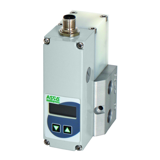
S ER IES ASCO NUMATICS™ INSTALLATION MANUAL Operating Elements Power supply, M12 plug Pressure output Protective ground - M4 connector Exhaust Pressure supply LC display Control keys Mounting hole Manual Pressure Adjustment (Manual Operation - Only for version with a display) If the supply voltage is cut off, after a reconnection of the supply voltage and by pressing the two arrow keys below the display at the same time, the pressure regulator will change to “Manual operation”... - Page 5 S ER IES ASCO NUMATICS™ INSTALLATION MANUAL Connector Pin Out / Cable Wiring Description 24 VDC voltage supply not connected Supply common not connected Body EMC screen View from soldering side M12 Class A & B Compatible Cables* and Accessories M12 Straight 5 Pin Female Single Ended Cable - Unshielded TC0505MIE000071P –...
-
Page 6: Analog Target Value - Output Pressure
S ER IES ASCO NUMATICS™ INSTALLATION MANUAL Analog Target Value - Output Pressure Setpoint Onset The maximum adjustment range for the zero point is from 0% to +100%. Maximum Output Maximum Input Pressure Pressure PMR (psi) MAP (psi) WARNING: Output pressures greater than the PMR (Pressure Maximum Range) will not be regulated by the valve, i.e. -
Page 7: Pneumatic Connection
S ER IES ASCO NUMATICS™ INSTALLATION MANUAL Pneumatic Connection The air flow direction is from connection 1 to 2. 1 Pressure supply at connection 1 2 Pressure output at connection 2 3 Air released at connection 3 Inch screw connections (pipe threads) are to be used. Each screw connection must be lined with a fitting plastic sealing ring. -
Page 8: Technical Characteristics
S ER IES ASCO NUMATICS™ INSTALLATION MANUAL Technical Characteristics Fluid Characteristics Fluids: A ir or neutral gas, filtered at 50 μm condensate-free, lubricated or unlubricated, class 5 according to ISO 8573- 1:2010 [7:4:4] Minimum Required pressure: At least 15 psi above the maximum outlet pressure Pressure range: 0 – 50 psi, 0 – 100 psi, 0 – 150 psi Fluid temperature: 0 ºC to 60 ºC (32 ºF to 140 ºF) Ambient temperature:... -
Page 9: Care And Maintenance
S ER IES ASCO NUMATICS™ INSTALLATION MANUAL Care and Maintenance Installation and Operating Instructions 1. Before putting the pressure regulator into operation, carry out a careful inspection of the electrical connections and the supply voltage (24 VDC ±10%). An overvoltage can damage the electronic systems. Recommended fuse protection T 0.5 A 2. - Page 10 S ER IES ASCO NUMATICS™ INSTALLATION MANUAL Dimensions: mm DN 4 Inline version Weight: 0.49kg (1.08lbs) (2x) (52) Programming interface M4 hole for earth screw (3x) Ø4.2 (2x) 35.39 17.15 DN 4 Subbase version Weight: 0.49kg (1.08lbs) (2x) 34.8 78.5 (72.7) M12 connector Programming...
- Page 11 S ER IES ASCO NUMATICS™ INSTALLATION MANUAL Dimensions: mm DN 4 Joinable subbase Weight: 0.3kg (0.66lbs) 25.8 (3x) 36.8 14.2 KM4/ DIN 74 T1 (2x) (4x) M4 x 8/10 (2x) Ø6 (3x) DIN Rail mount: 10.5 EN 50022 35x7.5 25.8 (2x) DN 8 Weight: 0.93kg (2.05lbs)
- Page 12 S ER IES ASCO NUMATICS™ INSTALLATION MANUAL Dimensions: mm DN 15 Weight: 1.33kg (2.93lbs) Programming interface M4 hole for earth screw Ø 4.2 (2x) 1/2 (3x) 17.15 30.5 30.5 57.5 Visit our website at ASCO.com or contact us at (800) 972-2726...
- Page 13 (82) 2-3483-1570 China (86) 21-3395-0000 Italy (39) 02-356931 Spain (34) 942-87-6100 Czech Republic (420) 235-090-061 Japan (81) 798-65-6361 United Kingdom (44) 1695-713600 Dubai - UAE (971) 4-811-8200 Mexico (52) 55-5809-5640 2/19 ASCO (USA) | Tel (1) 888-686-2842 | an.insidesales@emerson.com | www.ASCO.com...