Table of Contents
Advertisement
Quick Links
Advertisement
Table of Contents

Related Manuals for ABB 8242


Summary of Contents for ABB 8242
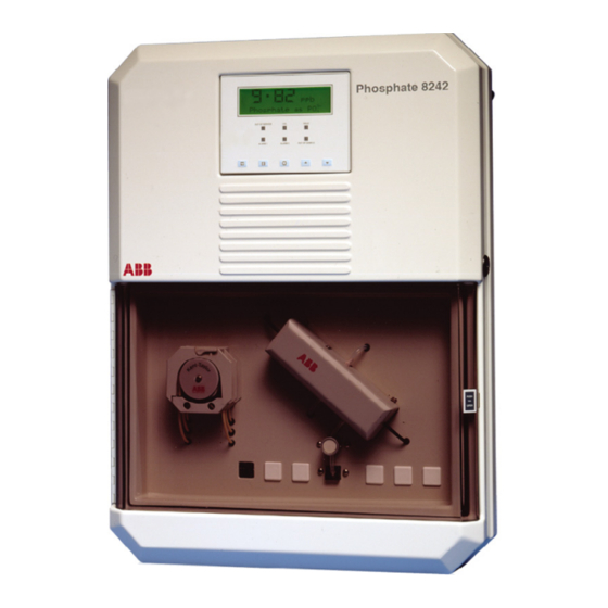
- Page 1 Model 8242 Instruction Manual Colorimetric Phosphate Monitor All Versions...
- Page 2 St Neots, U.K. – Cert. No. Q5907 environmental applications. Stonehouse, U.K. – Cert. No. FM 21106 As a part of ABB, a world leader in process automation technology, we offer customers application expertise, service and support worldwide. EN 29001 (ISO 9001) We are committed to teamwork, high quality manufacturing, advanced technology and unrivalled service and support.
-
Page 3: Table Of Contents
CONTENTS Section Page Section Page INTRODUCTION ..........2 MAINTENANCE ..........25 Brief Description ..........3 Chemical Solutions .......... 25 Training .............. 3 8.1.1 Reagent Solution ....... 25 Location and Function of 8.1.2 Standard Solutions ......25 the Main Components ........3 8.1.3 Rinse Solution for Internal Pipework ....... -
Page 4: Introduction
This feature is available in single stream monitors access to the rear of the panel for maintenance. only. The 8242 Phosphate Monitor carries out the measurement as follows: a) The sample is presented to a constant head unit and any excess is allowed to overflow. -
Page 5: The Main Components
1 INTRODUCTION To gain access to the electronics section follow steps 1 to 3. To gain access to the liquid handling section follow steps 4 and 5. Open the main door of the enclosure. OUT OF SERVICE HOLD Unlock the main door of the enclosure. ALARM 1 ALARM 2 OUT OF SAMPLE... -
Page 6: Installation
Power supplies should also be adjacent. Ambient temperature within the range 5 C to 40 C. recommended. ABB Ultrafiltration Units are the most suitable for the purpose, details of which are available on request. For power applications a 60 micron, in-line filter should be used –... -
Page 7: Sample Connections
2 INSTALLATION… 2.5 Sample Connections – Fig. 2.2 Notes. Connect inlet and outlet tubes as shown in Fig. 2.2A (single • Use tube of inert material, e.g., p.v.c. stream) and Fig. 2.2B (multi-stream). • The sample inlet tube must incorporate a shut-off valve at its up-stream end. -
Page 8: External Electrical Connections
…2 INSTALLATION 2.6 External Electrical Connections – Information. Because the current output is isolated, Figs. 2.3 to 2.5 the negative terminal MUST be connected to earth (ground) if connecting to the isolated input of another device. Warning. • Although certain instruments are fitted with internal fuse The setting of the range of the current output is covered on protection, a suitably rated external protection device, Programming Page 4 (see Section 6.4). - Page 9 2 INSTALLATION… MAINS MAINS Power Supply Input Power Supply Input INPUT INPUT Alarm 1 Stream 1 Concentration Alarms Alarm 2 Stream 2 ‘Out of Sample’ Indication Stream 3 Alarm Relay Configurable as concentration or ‘Out of Sample’ Alarm Relay Stream 4 Stream 5 Not Used Stream 6...
-
Page 10: Relay Contact Protection And 8.2.6 Interference Suppression
3 SETTING UP …2 INSTALLATION 2.7 Relay Contact Protection and Interference Note. Before proceeding any further, ensure that Suppression – Fig. 2.6 the HOLD switch is ON; all other switches are set to OFF If the relays are used to switch loads on or off the relay on the right hand side of the electronics unit –... -
Page 11: Liquid Handling Section
4 LIQUID HANDLING SECTION …3 SETTING UP g) Fit the pressure plate platen on the peristaltic pump (see 4.1 Principle of Operation – Fig. 4.1 Section 8.2.6) and switch the pump on with the switch on The chemical method used in the monitor utilizes the reaction the side of the monitor. - Page 12 …4 LIQUID HANDLING SECTION Out of Sample Constant Float Switch Head Unit (see Fig. 4.3) Blue Sample Filters Overflow Drain Sample Inlet Sample N o t e . S a m p l e Drain Emergency Sample Container filters are used in power applications only.
-
Page 13: General Operation
4 LIQUID HANDLING SECTION… 4.2 General Operation – Figs. 4.2 and 4.3 Information. The dynamic mixer consists of a The sample enters the constant head unit situated at the small stirrer situated in a chamber in the mixer block and is bottom of the instrument case –... -
Page 14: Multi-Stream Operation
…4 LIQUID HANDLING SECTION Start of Sequence Color Compensation Applied Finish of Sequence Nominally eight fill/drain cycles Further eight fill/drain cycles (approximately 10 minutes) for recovery on sample Energized De-energized Fig. 4.4 Color Compensation Timing Sequence for Single Stream Instruments 4.3 Multi-Stream Operation If the stream is unavailable throughout the sampling period the monitor selects the next stream in the sequence. -
Page 15: Manual Grab Sample Facility
4 LIQUID HANDLING SECTION 4.4 Manual Grab Sample Facility 4.5 Optical System – Figs. 4.6 and 4.7 A facility is provided to pass a grab sample through the monitor The optical system comprises a tungsten halogen exciter lamp manually which has been taken from another sample point. If mounted between two photocells. -
Page 16: Electronics Section
5 ELECTRONICS SECTION 5.1 Front Panel Controls - Figs. 5.1 and 5.2 5.3 L.E.D. Indicators The program controls comprises five tactile membrane Out of switches. In normal operation the switches are used to view Service Indicates that the monitor out of service alarm is the measured variable, the concentration alarm values, active, the source is indicated on Programming diagnostics... - Page 17 5 ELECTRONICS SECTION… Liquid Crystal Display LED Indicators. See OUT OF SERVICE HOLD Section 5.3 for functions. ALARM 1 ALARM 2 OUT OF SAMPLE Page Advance - Used, via the security code, for advancing through the main program pages, e.g. to advance from Program Page 4.0 to 5.0.
-
Page 18: Microprocessor Unit
…5 ELECTRONICS SECTION 5.4 Microprocessor Unit – Figs. 5.3 and 5.4 Drive Board Provides outputs to drive internal functions, i.e. stream section, The electronic section comprises six main circuit boards which calibration valves, pump motor, carry out the following functions: and heater control. - Page 19 5 ELECTRONICS SECTION...
-
Page 20: Single Stream Programming
6 SINGLE STREAM PROGRAMMING In normal operation (Operating Pages 0 and 1) the display gives indication of the units of measurement, diagnostics, calibration information and time. Selection is made by means of the switches. Operation of the switch enables a series of 'programming' pages to be displayed. - Page 21 6 SINGLE STREAM PROGRAMMING…...
- Page 22 …6 SINGLE STREAM PROGRAMMING Page 0. Normal operation display page. mg/l Phosphate as PO 6.1 Page 1 - Diagnostics Indicates the date when the next relevant routine maintenance DIAGNOSTIC INFORMATION PAGE 1.0 is required. When the date is exceeded, ‘overdue’ is displayed Next 5 weekly service = DD/MM and the ‘Out of Service’...
- Page 23 6 SINGLE STREAM PROGRAMMING… All programming Page 2.2 parameters normally set to NO, set ROUTINE MAINTENANCE. PAGE 2.2 to YES as required (setting is maintained). Energise AUTO ZERO valve = NO Energise SECONDARY CAL valve = NO Used to energize the appropriate solenoid valve for test Energise EMERGENCY SAMPLE valve = NO purposes and operating the monitor on synthetic solutions.
- Page 24 …6 SINGLE STREAM PROGRAMMING Shows the current software issue level. SET UP INSTRUMENT PAGE 3.1 Set the required control temperature within the range 20 to Software issue = 45C in 0.1C increments. This temperature should be set to Control temperature = xx.x‘C Display units = <units>...
- Page 25 6 SINGLE STREAM PROGRAMMING FACTORY SETTINGS PAGE 6.1 WARNING : These parameters are factory set and should not normally require adjustment. They can only be set up if the necessary equipment is available. DO NOT PROCEED WITHOUT CONSULTING THE OPERATION MANUAL. Used for diagnostic purposes only.
-
Page 26: Calibration
7 CALIBRATION 7.1 Method of Calibration reagent (normally five weeks). If the zero offset is outside factory pre-set limits, a calibration fail alarm is initiated and the 'Out of Calibration of the monitor is carried out by replacing the Service' l.e.d. is lit. sample solution sequentially with two solutions of known phosphate concentration –... -
Page 27: Maintenance
8 MAINTENANCE 8.1 Chemical Solutions c2) Dissolve 250 g (1 g) analytical reagent grade ammonium molybdate, (NH O, in approximately 2 liters of The reagent and standard solutions listed below are high purity water. necessary to maintain the monitor in operation. For either concentration Caution. -
Page 28: Scheduled Servicing
…8 MAINTENANCE Warning. Sodium hydroxide is extremely caustic Caution. All unused solutions must be discarded; and must be handled with great care. Wear gloves and the containers must be rinsed with high purity water before eye protection. refilling with the fresh solution. One liter of the rinse solution is prepared as follows: c) Replace pinch tube between the cuvette and the drain a) Dissolve 100 g of sodium hydroxide pellets, NaOH, in... -
Page 29: Rinsing Internal Pipework
8 MAINTENANCE… 8.2.4 Rinsing Internal Pipework 8.2.7 Replacement of Plumbing Tubing – Fig. 8.2 All the following items are included in the Consumable Spares Important Note. Kit. • It cannot be stressed strongly enough that the five- Caution. It is essential that the correct tube, weekly chemical rinse with the NaOH rinse solution is vitally important. - Page 30 …8 MAINTENANCE Note. • The bungs are designed to grip the pump tube when compressed by the platen. Two sizes of tube are used so it is essential that the correct size of bung is fitted. • It is immaterial which tube passes over which pump roller, but for neatnes the front tube should be de- Remove the pump platen by gassed sample, the centre tube reagent and the raw...
- Page 31 8 MAINTENANCE… 0212 175 Violet 0212 214 0212 003 Violet 0212 175 0212 020 0212 214 0212 007 Green 0212 222 Blue 0212 007 0212 175 Blue 0212 362 Blue Blue 0212 362 Green Yellow = Pipe connector Blue 0212 156 0212 362 Part No Tube Specification...
-
Page 32: Unscheduled Servicing
…8 MAINTENANCE 8.4 Unscheduled Servicing Caution. Check that there have been no unauthorized modifications, e.g., incorrect tubing fitted. 8.4.1 Monitor Diagnostic Information The monitor is fitted with extensive diagnostics which provide In the majority of cases any problems experienced are information on routine servicing and problems that have generally found to be associated with the chemistry and the developed. -
Page 33: Effects Of Loss Of Power To The Monitor
8 MAINTENANCE… If the monitor fails to produce results as expected, the most likely cause is the standards, either contaminated when handled or (and most likely) made up with poor quality water, possibly containing background phosphate. Incorrectly prepared reagent may give a poor calibration factor. -
Page 34: Low/High Calibration Factor Value
…8 MAINTENANCE 8.5.2 Low/High Calibration Factor Value 8.5.4 Simple Electronic Response Test a) Check and, if necessary, replace the standard solutions. a) Remove the optical system cover. b) Check and, if necessary, replace the reagent solution. b) Switch 'Default calibration parameters' to YES on Programming Page 2.1. -
Page 35: Aligning The Exciter Lamp
8 MAINTENANCE… b) To avoid spillages in the next step depress the pinch valve Reference Photocell plunger for two to three seconds to drain the cuvette. Lamp Housing Measuring Housing Cuvette c) Remove the optical system cover if not already done so. Measuring Lamp Remove the cuvette inlet tube from the cuvette connector. -
Page 36: Color Compensation Solenoid Valves
9 SPECIFICATION …8 MAINTENANCE 8.7 Color Compensation Solenoid Valves Installation Information There is no maintenance required for these valves (SV4 and Install the monitor where the following conditions can be SV5 – see Fig. 1.1). If they have been removed from the base maintained: for any reason, please refer to Fig. -
Page 37: Spares
8240 114 Float Switch Assy. – 'Out of Sample' ....1 range of the monitor. 8242 134 Float Switch Assy – 'Out of Reagent' ....1 Maximum voltage load: 15 V. 8240 090 Sample De-gasser ........... 1 Current Outputs 8242 150 Mixer Block Assembly ........ - Page 38 8242 192 EPROM – multi-stream (French) ..... 1 8242 193 EPROM – multi-stream (Spanish) ....1 8242 185 EPROM – single stream + serial (English) ..1 8242 186 EPROM – single stream + serial (German) ..1 8242 187 EPROM – single stream + serial (French) ..1 8242 188 EPROM –...
-
Page 39: Appendix A - Multi-Stream Programming
APPENDIX A – MULTI-STREAM PROGRAMMING In normal operation (Operating Pages 0 and 1) the display gives indication of the units of measurement, diagnostics, calibration information and time. Selection is made by means of the switches. Operation of the switch enables a series of 'programming' pages to be displayed. - Page 40 …APPENDIX A – MULTI-STREAM PROGRAMMING...
- Page 41 APPENDIX A – MULTI-STREAM PROGRAMMING… Stream Page 0.0 is a fixed display on the indicated stream. The mg/l switches are used to select the stream required. Phosphate as PO Stream mg/l The display on Page 0.1 continuously scrolls, at two second intervals, all the streams fitted.
- Page 42 …APPENDIX A – MULTI-STREAM PROGRAMMING A2 Page 2 - Maintenance & Calibration MAINTENANCE AND CALIBRATION. PAGE 2.0 Enter security code xxxx Enter the value of the previously entered security code. Set the following three parameters to YES when the tasks are carried out.
- Page 43 APPENDIX A – MULTI-STREAM PROGRAMMING… SECONDARY CALIBRATION SEQUENCE PAGE 2.5 Reading during calibration prior to compensation. Reading = xxx<unit> Remaining time to the end of the Secondary Calibration Time to compensation = xx min Abort SEC calibrations = NO sequence. When set to YES the sequence is aborted.
- Page 44 …APPENDIX A – MULTI-STREAM PROGRAMMING Set to one of the following ranges: 0 to 10, 0 to 20 or 4 to SET UP CURRENT OUTPUT PAGE 4.1 20mA. Output type = xx to xx mA If required, the instrument can automatically transmit a Test output = NO Up scale sample time = xx mins percentage of the full scale test signal: 0, 25, 50, 75, 100% of...
- Page 45 APPENDIX A – MULTI-STREAM PROGRAMMING… ELECTRICAL CALIBRATION. PAGE 6.2 Reading = xxx<units> Displays the output of the photocell pre-amplifiers. Used only Lamp alignment V read = x.xxx Volts Lamp alignment V ref x.xxx Volts for information and photocell balance adjustment. Alter factory settings security code xxxx...
-
Page 46: Appendix B - Wiring Schematic
APPENDIX B – WIRING SCHEMATIC Upper Lower Earth Point Fig. B1 Wiring Schematic... -
Page 47: Appendix C - Replacing Software Eprom
APPENDIX C – REPLACING SOFTWARE EPROM 6) Fit the replacement chip ensuring correct orientation in its Warning. Switch off the monitor and electrically socket. isolate it before carrying out the following steps. 7) Complete the procedure as follows: • Plug the PCB onto the mother board; Caution. - Page 48 NOTES...
- Page 49 NOTES…...
- Page 50 …NOTES...
- Page 51 PRODUCTS & CUSTOMER SUPPORT Products Customer Support Automation Systems ABB Automation provides a comprehensive after sales service • for the following industries: via a Worldwide Service Organization. Contact one of the – Chemical & Pharmaceutical following offices for details on your nearest Service and Repair –...
- Page 52 ABB Automation Inc. Oldends Lane, Stonehouse 125 E. County Line Road Gloucestershire, GL10 3TA Warminster, PA 18974 ABB has Sales & Customer Support expertise in over 100 countries worldwide Tel: +44 (0)1453-826-661 Tel: +1 215-674-6000 Fax: +44 (0)1453-827-856 Fax: +1 215-674-7183...