
Related Manuals for Endress+Hauser Mycom CLM 152


Summary of Contents for Endress+Hauser Mycom CLM 152
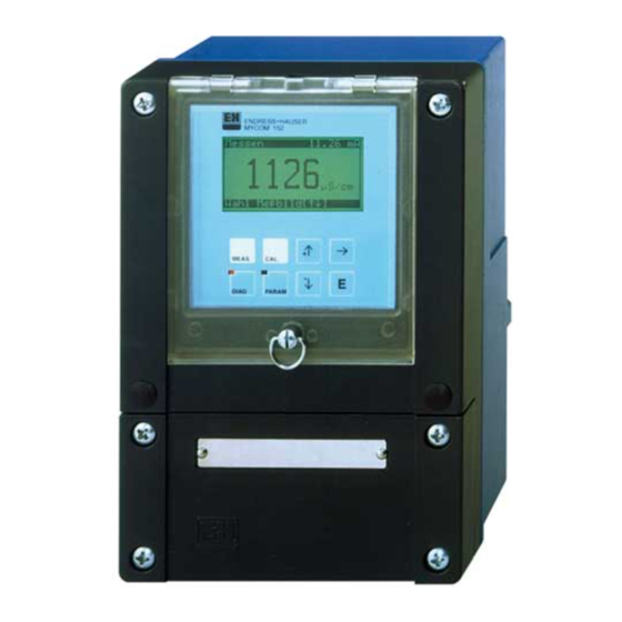
- Page 1 Mycom BA 144C/07/en/07.00 No. 51501096 Software Version 2.00 or higher CLM 152 Conductivity Measuring Transmitter Operating Instructions MEAS DIAG PARAM Endress Hauser The Power of Know How...
- Page 2 You want to familiarise yourself with the instrument. All you need to know can be found in these chapters. General information Safety Instrument description You want to install and start up the instrument. All the necessary steps are described in these chapters. First start-up Installation You want to operate or reconfigure the instrument.
-
Page 3: Table Of Contents
Electrical connection of the Mycom CLM 152 ........ -
Page 4: General Information
Note! This symbol draws attention to important items of information. Conformity certificate The Mycom CLM 152 conductivity measuring transformer was developed and manufactured in compliance with European standards and directives. Note: An EC Declaration of Conformity can be obtained from Endress+Hauser. -
Page 5: Safety
Mycom CLM 152 Safety Safety Intended application The Mycom CLM 152 measuring transmitter is and the addition of optional plug-in modules, a microprocessor-controlled measuring and it can be adapted to different process control instrument used to determine and applications. If the version of the Mycom evaluate specific conductivity. -
Page 6: Instrument Description
Mycom CLM 152 Instrument description Instrument description Applications The Mycom CLM 152 measuring transmitter is • Foodstuffs industry specially designed for carrying out measuring • Pharmaceuticals and control tasks in the following applications: • Chemical process engineering • Water treatment •... -
Page 7: Measuring System
• a suitable conductivity measuring cable following components: with or without junction box for extending the cable • an inductive or conductive conductivity • the Mycom CLM 152 measuring transmitter sensor with an integrated temperature • Ex-version transmitter: conductive: combinable with all sensor Pt 100... -
Page 8: Instrument Variants
Mycom CLM 152 Instrument description Instrument variants You can identify the instrument variant and the required power supply from the order code on the nameplate. CLM 152 conductivity and resistance measuring transmitter Field housing, ingress protection IP 65, for wall mounting Signal outputs 0 / 4 ... - Page 9 Instrument description Mycom CLM 152 lm152e03.chp (Equipment and certificate, see above) Power supply 230 V, 50 / 60 Hz 115 V, 50 / 60 Hz 200 V, 50 / 60 Hz 24 V, 50 / 60 Hz 100 V, 50 / 60 Hz...
-
Page 10: Accessories
• Kit for panel and post mounting the package: (only mounting version B) • 1 measuring point label with 2 nails • 2 cable glands Pg 13.5 Overview of connectable Endress+Hauser conductivity sensors Conductivity measurement: Two-electrode CLS 30 k = 10 cm... - Page 11 Instrument description Mycom CLM 152 lm152e03.chp 3.7.3 VBM junction box for inductive sensors The VBM junction box must be installed to extend the connecting cable of the CLS 52/CLS 50 sensor beyond the standard cable length by means of a special cable to the measuring transmitter.
-
Page 12: Installation
If you have any questions, please contact Check the scope of delivery against your your supplier or the Endress+Hauser sales purchase order and the shipping documents: agency (see rear page of this document). • Scope of delivery •... -
Page 13: Installation
Mycom CLM 152 MONTAGE.CDR Mounting accessories CYY 101 weather protection cover for operating the Mycom CLM 152 outdoors. The post mounting kit for the weather protection cover is also required for installing on vertical or horizontal pipes (Fig. 4.5). Material: stainless steel Order No. -
Page 14: Electrical Connection Of The Mycom Clm 152
Installation Mycom CLM 152 Electrical connection of the Mycom CLM 152 Warning: Warning: • All signal-carrying lines must be Only properly trained personnel is screened in compliance with allowed to work on the instrument when the system is live and VDE 0165 and routed separately other control lines. - Page 15 Mycom CLM 152 Installation lm152e04.chp 4.4.1 Connecting the Mycom CLM 152 in non-hazardous area F101 250 Vac / 2A ( cos 125 Vdc / 3A FCL1 L L N L+ L+ L – Relay contact 88 87 85 86 Power...
- Page 16 Installation Mycom CLM 152 Note: Note • • The contact position on mains All switching contacts are failure or when a fault occurs can interference-suppressed. be set for “contact 1" and ”alarm External loads must also be contact” through the system interference-suppressed.
- Page 17 Mycom CLM 152 Installation lm152e04.chp FCYK additional module: Comprising 3 relays for limit contactor or Chemoclean Contact 2 Contact 3 Contact 4 Contact 2 Contact 2 Contact 3 Contact 3 Contact 4 Contact 4 Connection of fcykcon.cdr Fig. 4.9 FCYK module, non-Ex...
- Page 18 For more information, see Chapter 10 Fig. 4.12 module profibus.cdr 4.4.2 Connecting the Mycom CLM 152-Z in Ex zone General instructions on Installation in hazardous areas Instruments with the letter Z in their model Conductive conductivity sensors from designation are produced and tested in...
- Page 19 Wiring compartment and wiring diagram Sicherung / fuse: 50076930 100V..230V 50076931 24Vac 50087807 24Vdc Analog FCL1 88 87 85 86 2x Optocoupler max. 30 Vdc / 100mA / 750mW Power- supply Wiring compartment of lm152arx.cdr Fig. 4.14 Mycom CLM 152-Z (Ex) Endress+Hauser...
- Page 20 Installation Mycom CLM 152 Conductivity input module (Ex) i Current output module (Ex) i Basic module FCL1 (Slot 1) FCYI (Slot 2) Temperature Conductivity Conductivity Temperature Fail Contact 1 Aux. voltage ϑ ϑ 11 12 13 14 15 16 17...
- Page 21 Mycom CLM 152 Installation lm152e04.chp Basic module Electrical data of contact circuit: max. output voltage ,max = 30 V max. output power ,max = 750 mW External wiring of output contacts on basic module: Only one intrinsically safe contact circuit (ia or ib) with ➀...
- Page 22 Installation Mycom CLM 152 FCYK-Ex additional module: Comprising 3 optocouplers acting as Contact 2 switching outputs for limit contactor or Contact 2 Chemoclean Contact 3 Contact 3 Contact 2 Contact 3 Contact 4 Contact 4 Contact 4 Outputs with npn transistors. The emitter terminals (E) must have negative potential in relation to the collectors (C).
- Page 23 Mycom CLM 152 Installation lm152e04.chp FCXI additional module: Comprising two contact inputs for Hold, Current input Contact inputs remote measuring range switch-over and analogue input with measuring transmitter power supply. Current input, positive Current input, negative Contact input 1 Contact input 1...
-
Page 24: Connecting Conductivity Sensors
Installation Mycom CLM 152 Connecting conductivity sensors Inductive sensors Conductivity sensors are connected via Caution: special multi-core, screened measuring cable. If you need to extend the measuring cables, Make absolutely sure you protect use the VBM junction box. plugs and terminals from moisture. - Page 25 Mycom CLM 152 Installation lm152e04.chp Conductive sensors Caution: Note: Make absolutely sure you protect • The instrument has a function to plugs and terminals from moisture. offset cable length and capacitance Moisture leads to inaccurate to compensate for cable resistance measuring results! (see Chapter 11.5.5 „Determine...
-
Page 26: First Start-Up
Mycom CLM 152 First start-up First start-up Measures before first power-up Before switching on the measuring transmitter for the first time, familiarise yourself with the operating instructions! Caution: Warning: Before switching on, check that all Before power-up, make sure that... - Page 27 First start-up Mycom CLM 152 lm152e05.chp Start-up / Checklist Request Selection options Factory settings User settings Chapter Language version A: Language version C: Deutsch, Deutsch, English, English, Language 7.1.5 English Français, Français Italiano Nederlands Japanese LC display 7.1.5 Set as desired “medium”...
- Page 28 Mycom CLM 152 First start-up Start-up / Checklist continued Request Selection options Factory setttings User settings Chapter 2xHold; Input contact 7.1.1 1xHold + 1xremote switch-over; 2xremote 2xHold (only with FCXI card) switch-over 2 relays Maintenance Maintenance, limit (for base version)
-
Page 29: Operation
Mycom CLM 152 Operation lm152e06.chp Operation Operating elements 4 keys for instrument configuration MEAS Status LED DIAG PARAM green: normal operation red: severe fault 4 Keys for starting LED with no function main groups Operating elements of LM152B-E.CDR Fig. 6.1... -
Page 30: Key Functions
• Return to next higher menu level Operating concept The function of the Mycom CLM 152 Select options or the configuration set-up measuring transmitter are divided into four within the sub-groups by using the menu main groups: selection (see above) or by editing a digit. - Page 31 Mycom CLM 152 Operation lm152e06.chp Note: If no input is made in a sub-group for longer than about 10 minutes, the instrument automatically returns to You can also change to another measuring mode (exceptions: main group when you are in a Calibration, Simulation and Start-up).
-
Page 32: Measured Value Display Formats
Operation Mycom CLM 152 Measured value display formats Press ↑ and ↓ to select between different Note: display formats for the screens. There are differences in the size of digits and the A contact state display only appears number of additional information items. - Page 33 Mycom CLM 152 Operation lm152e06.chp Resistance measurement (only for conductive sensor) Main display: Resistance measured value in MΩcm or kΩcm 1st meas. (large characters for reading from a distance) value Suppl. info: Measuring range (only for remote measuring range display...
-
Page 34: Locking Functions
Operation Mycom CLM 152 Locking functions The Mycom CLM 152 has two operating Note: levels which you can access by entering four-digit numebr codes: The instrument is supplied in unlocked state. • Maintenance • Specialist Disabled menus are not displayed. -
Page 35: The „Short Operation Menu
Mycom CLM 152 Operation lm152e06.chp The „Short Operation menu“ → Short Operation PARAM • Hold on / off The Short Operation menu gives you direct • Manual / Auto toggle access to the main functions without having to • Setpoints for limit contactor run the entire configuration menu. -
Page 36: Instrument Configuration
Instrument configuration Mycom CLM 152 Instrument configuration Note: The complete menu structure is illustrated on the back pages of this manual for an overview. PARAM → Set-up guide Chapter 5.2 • Guided run through main menus • Hold on / off, •... -
Page 37: System Configuration
Mycom CLM 152 Instrument configuration lm152e07.chp System configuration PARAM → Instrument data → System configuration → Measured variable 7.1.1 → Code 7.1.3 → Output contacts 7.1.4 → General settings 7.1.5 7.1.1 Measured variable Function Selection Factory setting... - Page 38 Current output 1: differential Current output 2: Cond. 1, Cond. 2, Temp. 1 or Temp. 2 7.1.2 Measuring range switch-over The Mycom CLM 152 has two options for Switch-over affects: switching over measuring ranges: • Current output • external remote measuring range •...
- Page 39 Mycom CLM 152 Instrument configuration lm152e07.chp Automatic internal measuring range switch-over (only with conductivity mode/single-circuit operation mode) Note: Here the Mycom switches automatically to the suitable measuring range. This requires the FCYK expansion module (electrical The function is activated connection see chapter 4.4.1).
- Page 40 Instrument configuration Mycom CLM 152 7.1.3 Code Function Selection Factory setting Enter required maintenance code 0000 ... 9999 0000 (0000 = no lock) Enter required specialist code 0000 ... 9999 0000 (0000 = no lock) 7.1.4 Output contacts Caution: •...
- Page 41 Mycom CLM 152 Instrument configuration lm152e07.chp Contact assignment in base version Select »Maintenance« Select »Limit« Select »USP« Failure contact Failure Failure Failure Tl. 85/86 Contact 1 Maintenance required Limit contact Tl. 87/88 Relay contact of non-Ex version on power failure:...
- Page 42 Instrument configuration Mycom CLM 152 7.1.5 General settings Function Selection Factory setting Language version A: Deutsch, English, Français, Italiano Select language English Language version C: Deutsch, English, Français, Nederlands, Japanese Input damping (size of time window over which Filter length, 0 (= off) ... 30 measurement is averaged;...
-
Page 43: Current Output
Mycom CLM 152 Instrument configuration lm152e07.chp Current output PARAM → Instrument data → General settings 7.2.1 → Current output 1 7.2.1 → Current output 2 7.2.1 7.2.1 Current output Current output signal: characteristics and allocation Function Selection... - Page 44 Instrument configuration Mycom CLM 152 Current output 2 Definition of parameter for second Cond. 1, Cond. 2, current output (only for instrument Temperature 1 Temperature 1, Temperature 2 with 2nd Cond. input) Measuring current range 0 ... 20 mA or 4 ... 20 mA 4 ...
- Page 45 Mycom CLM 152 Instrument configuration lm152e07.chp Sensor MR 1 MR 2 MR 3 MR 4 MR 5 Conductivity µ µ CLS 50 S/cm 2.00 – 20.00 mS/cm 20.0 – 200.0 mS/cm 200 – 1000 mS/cm 0 – 200.0 S/cm 200 – 2000 µ...
- Page 46 Instrument configuration Mycom CLM 152 Sensor Range 20 mA input Input range of knee value Conductivity 20.0 µS/cm – 200.0 mS/cm CLS 50 200 mS/cm – 1000 mS/cm 200 µS/cm – 200.0 mS/cm CLS 52 2.00 mS/cm – 1000 mS/cm 0.200 µS/cm –...
- Page 47 Mycom CLM 152 Instrument configuration lm152e07.chp Sensor Range 20 mA input Conductivity 200 µS/cm – 1000 mS/cm CLS 50 CLS 52 2.00 mS/cm – 1000 mS/cm 0.200 µS/cm – 200.0 µS/cm k = 0.01 2.00 µS/cm – 2000 µS/cm k = 0.1 20.0 µS/cm –...
- Page 48 Instrument configuration Mycom CLM 152 Example of a current output table for log 3 Current output [%] Conductivity [µS/cm] Current output [%] Conductivity [µS/cm] 4.47 0.14 6.31 8.91 0.28 12.6 17.8 0.56 25.1 0.79 35.5 1.12 50.1 1.58 70.8 2.24 3.16...
-
Page 49: Temperature Compensation
Mycom CLM 152 Instrument configuration lm152e07.chp Temperature compensation → Instrument data PARAM →Temperature → Temperature compensation 7.3.1 → Temperature measurement 7.3.2 The temperature coefficient indicates the change in conductivity per degree of temperature. It is dependent on the chemical composition of the solution and on its concentration and temperature). - Page 50 Instrument configuration Mycom CLM 152 7.3.1 Temperature compensation Function Selection Factory setting Measuring range selection with Measuring Measuring ranges 1 ... 4 activated remote switch-over range 1 No comp., linear, NaCl as per IEC 746, Type of temperature compensation Tc table, ultrapure water NaCl,...
- Page 51 Mycom CLM 152 Instrument configuration lm152e07.chp 7.3.2 Temperature measurement For the temperature measurement, a temperature compensation must be carried out either manually or automatically. Manual temperature compensation (MTC): Automatic temperature comp. (ATC): Without temperature sensor. To obtain a precise temperature...
-
Page 52: Calibration Presettings
Instrument configuration Mycom CLM 152 Calibration presettings → Instrument data PARAM → Calibration Function Selection Factory setting Hold for calibration yes, no Enter temperature coefficient Tc of 0.00 ... 10.00 %/K 2.10 %/K calibration solution Enter temperature of calibration –35.0 ... +250.0 °C 25.0 °C... - Page 53 Mycom CLM 152 Instrument configuration lm152e07.chp Function Selection Factory setting Automatic ON Switch on/off clean function, set Automatic OFF Automatic OFF parameters Settings If „Setting» selected Interval Type of cleaning program Interval cleaning, Week program cleaning If »Interval cleaning« selected Cleaning cycle 0.1 ...
-
Page 54: Substance Selection / Concentration Measurement
Instrument configuration Mycom CLM 152 Substance selection / Concentration measurement Note: → Instrument data PARAM This menu only appears when the → Substance concentration measurement is set as selection the measuring type (see Parameter menu, Chap. 7.1.1). Function Selection Factory setting... -
Page 55: Limit Configuration
Mycom CLM 152 Limit configuration lm152e08.chp Limit configuration Limit contacts Each contact is either permanently closed or Example of two permanently open. limit contacts Contact MIN function MAX- function The nature and scope of the possible settings are determined by the equipment available in... -
Page 56: Instruments With Two Contacts
Limit configuration Mycom CLM 152 Instruments with two contacts → Instrument data PARAM → Limit contactor Function Selection Factory setting Limit configuration Limit Select group Alarm configuration configuration Operating mode If „Limit configuration“ selected Switch on/off output on, off Limit see Table “Cell dependence“... -
Page 57: Instruments With Five Contacts
Mycom CLM 152 Limit configuration lm152e08.chp Instruments with five contacts → Instrument data PARAM → Limit contactor Function Selection Default Limit configuration Limit Select group Alarm configuration configuration Operating mode If „Limit configuration“ Limit contactor 1 Limit Select limit contactor... -
Page 58: Usp Function (Conductive)
→ Instrument data PARAM → USP contact According to USP guidelines (“United States Monitoring is automatic and can be selected Pharmacopeia”), the Mycom CLM 152 can via the Instrument data menu. The measure and monitor non-compensated user-selected setting for temperature conductivity. - Page 59 Mycom CLM 152 Limit configuration lm152e08.chp The USP function can be activated from the Instrument data/USP menu. After activation, you can make the following settings: Function Selection Factory setting On delay 0 ... 60 s Setting range sensor-dependent Hysteresis 0 µS/cm...
-
Page 60: Calibration
Calibration Mycom CLM 152 Calibration Entering a code Enter a code and confirm by pressing E to The system requests you to enter the code access the sub-levels of the menus. The when you entered a repairman or a specialist levels are then enabled (see Chapter 6.6). - Page 61 Mycom CLM 152 Calibration lm152e09.chp 9.2.2 Determining the cell constant Measure the conductivity of a calibration • Wait until the measured value stabilises solution (of precisely known conductivity) • Accept the measured value by pressing (see Chap. 3.7.2): »E« When you set the display to the conductivity •...
- Page 62 Calibration Mycom CLM 152 Table continued Function Selection Default If »End Cal.« selected Return to Measuring mode If »Repeat Cal.« selected Calibrate Sensor 1 Sensor 1 Return to Select sensor (above) If »Cal. channel 2" selected Calibrate sensor 2 Sensor 2 Return to Select sensor (above) 9.2.3...
- Page 63 Mycom CLM 152 Calibration lm152e09.chp Determining the adaptation factor Function Selection Default Sensor 1 Select sensor (not for single-circuit) Sensor 1 Sensor 2 Leave sensor in Message process Display conductivity of calibration solution current Tc, temperature Current Enter setpoint of calibration solution 0 µS/cm ...
-
Page 64: Conductive Calibration
Calibration Mycom CLM 152 Conductive calibration → Enter cell constant 9.3.1 → Determine cell constant 9.3.2 9.3.1 Numerical calibration by entering the cell constants The cell constant is measured precisely at the Cell constant Input range factory and is entered directly in cm . -
Page 65: Profibus Interface
FCYP module In the simplest case, the complete measuring The maximum number of measuring cell consists of the Mycom CLM 152 and the transmitters in one bus segment is FCYP module (see Chapter 4, Fig. 4.12), a determined by their current drain, the... -
Page 66: Bus Address
® PROFIBUS interface Mycom CLM 152 10.3 Bus address ® Every instrument is assigned a unique bus Setting the PROFIBUS address (menu address: selection): ➜ set address (1 to 126) at switches 1-7 • Param (Specialist) ➜ Set switch 8 to OFF: •... -
Page 67: Device Master File / Type File
® Mycom CLM 152 PROFIBUS interface lm152e10.chp 10.4 Device master file / Type file Device master files are required to use the The meanings of the individual device ® PROFIBUS . They must be created as parameters are contained in the Siemens TYP files. -
Page 68: System Integration Via Plc
Graphical user interface Fig. 10.4 of Commuwin II SC-IDE2.CDR 10.6 System integration via PLC The Mycom CLM 152 measuring transmitter PROFIBUS-PA parameters are provided using supplies measured values (OUT) cyclically the acyclical service. using the PROFIBUS-PA protocol. Other Command Type... - Page 69 ® Mycom CLM 152 PROFIBUS interface lm152e10.chp Data format OUT Byte Date Data format Measured value Measured value IEEE 754 floating point number Measured value (format always mS/cm; kΩ cm or %) Measured value = Instrument OK Instrument status = Fault (alarm present)
-
Page 70: Profibus-Pa Parameters
® PROFIBUS interface Mycom CLM 152 10.7 PROFIBUS-PA parameters Parameter Matrix Index Data type Read Write Data (Slot = 1) length Composite List Directory Octet String DEVICE_ID V99H0 Octet String Actual Error Unsigned 16 Device Bus Address Integer 8 Main measured value Float Temp. -
Page 71: Instrument Diagnostics
Mycom CLM 152 Instrument diagnostics lm152e11.chp Instrument diagnostics → Error classification 11.1 → Error list and error log 11.2 → Error table 11.3 → Information list / Logbook 11.4 DIAG → Air set information (inductive only) 11.3... -
Page 72: Error Table
Check terminals, lines and poss. connected devices E016 Current loop 2 open Sensor error (inductive only) E017 Send sensor to your Endress+Hauser agency for examinaton or request Service E018 Sensor error channel 2 (inductive only) Maintenance required E036 Calibrating range of sensor 1 exceeded Recalibrate sensor;... - Page 73 Mycom CLM 152 Instrument diagnostics lm152e11.chp Faults Display Corrective action E055 Display range of undershot E056 Display range of 2 undershot Check measurement, control and E057 Display range of exceeded terminals, poss. check measuring transmitter and measuring cable with E058 Display range of 2 exceeded simulator.
- Page 74 Instrument diagnostics Mycom CLM 152 Warnings Display Corrective action E080 Range for current output 1 too small Enlarge range in “Current outputs” E081 Range for current output 2 too small E142 Knee point outside current output range 1 Correct cnfiguration in “Current outputs”...
-
Page 75: Information List / Logbook
On the differential instrument, there is Air Set information for each sensor. 11.6 Calibration history Caution: The Mycom CLM 152 measuring transmitter provides access to automatically recorded logs under the „Diagnostics“ and „Calibration When you change the operating history“ menu options which are a convenient mode or reset the instrument with way of assessing sensor status. -
Page 76: Service
Instrument diagnostics Mycom CLM 152 11.7 Service → Service → Simulation 11.7.1 DIAG → Internal data 11.7.2 → Factory settings 11.7.3 → Instrument check 11.7.4 → Special functions 11.7.5 11.7.1 Simulation Function Selection Set present 0.00...22.00 mA... - Page 77 Mycom CLM 152 Instrument diagnostics lm152e11.chp 11.7.3 Factory settings Function Selection Abort set config (accept changed slot assignment), setting data only, Factory settings calibration data only, (instrument reset) all data, (Service data, logbook, reset counter, message log ⇒ only for authorised service personnel, only with service code)
- Page 78 Instrument diagnostics Mycom CLM 152 11.7.5 Special functions Function Description Optimisation, Select special functions Checksum correction, Reset If “Optimisation” selected Measure temperature coefficient Tc Determine temperature coefficient of a measuring medium. Immerse sensor and temperature sensor in medium sample. The sample temperature...
- Page 79 The Mycom CLM 152 measuring transmitter then checks the stability of the measured value. When stability is reached, the current value is saved.
-
Page 80: Maintenance And Service
Fuse holder in Fig. 12.1 non-Ex version 12.3 Repairs Repairs may only be carried out directly by the manuafacturer or by the Endress+Hauser Service Organisation. A list of Endress+Hauser service agencies can be found on the back page of this manual. Endress+Hauser... -
Page 81: Appendix
Mycom CLM 152 Appendix lm152e13.chp Appendix 13.1 Technical data 13.1.1 Technical data, inductive Sensor independent data Measuring range non-compensated Measuring range compensated Measurement deviation ±0,5 % of measured value ± 3 digits Reproducibility ±0,2 % of measured value ± 3 digits Cable length max. - Page 82 Appendix Mycom CLM 152 CLS 52 sensor data 0 µS/cm ... 2000 mS/cm General data Lower measuring range limit (non-compensated) < 3 seconds over total measuring range (single-circuit Reaction time (T instrument) Temperature measurement Temperature sensor Pt 100 Class A as per IEC 751 Temperature response time ...
- Page 83 Mycom CLM 152 Appendix lm152e13.chp 13.1.2 Technical data, conductive Conductivity / resistance / Measuring and display ranges for conductivity concentration measurement Measuring range (MR) 1) Cell constant k Display range (DR) 0.0 nS/cm ... 600.0 µS/cm 0.0 µS/cm ... 200.0 µS/cm 0.01 cm...
- Page 84 Appendix Mycom CLM 152 13.1.4 General technical data General data Manufacturer Endress+Hauser Instrument name Mycom CLM 152 Limit and alarm functions Function Limit contactor Function type MIN or MAX Setpoint settings (in absolute values) 0 ... 100 % of display range Hysteresis for switch contacts (in absolute figures) 1 ...
- Page 85 Mycom CLM 152 Appendix lm152e13.chp Temperature compensation Range for linear and freely programmable T values –35 ... 250 °C Range for NaOH 0 ... 85.0 °C 0 ... 75.0 °C 0 ... 75.0 °C 0 ... 80.0 °C General technical data (continued)
-
Page 86: Connection Examples Inductive
Appendix Mycom CLM 152 13.2 Connection examples inductive 13.2.1 Base-acid recycling with concentration measurement mylf-01e.cdr Failure Maint. requirement Function check Limit 1 Endress+Hauser... - Page 87 Mycom CLM 152 Appendix lm152e13.chp 13.2.2 Differential measurement for fruit-juice production mylf-02e.cdr Failure Maint. requirement Function check Endress+Hauser...
-
Page 88: Connection Examples Conductive
Appendix Mycom CLM 152 13.3 Connection examples conductive 13.3.1 Limit contactor, NAMUR contacts mylf-03e.cdr Failure Maint. requirement Function check Limit 1 Endress+Hauser... - Page 89 Mycom CLM 152 Appendix lm152e13.chp 13.3.2 Chemoclean, NAMUR contacts mylf-04e.cdr Failure Maint. requirement Function check Water Cleaner Endress+Hauser...
- Page 90 Appendix Mycom CLM 152 13.3.3 Differential measurement, limit contactor, NAMUR contacts mylf-05e.cdr Failure Maint. requirement Function check Limit1 Limit 2 Endress+Hauser...
-
Page 91: Index
Connecting conductivity sensors ..24 Connecting the Mycom CLM 152 in Ex zone 16 General information....2 Connecting the Mycom CLM 152 in General settings . - Page 92 Index Mycom CLM 152 IEEE 754 floating point number ..67 Off delay ......54 Inactive errors .
- Page 93 Mycom CLM 152 Index lm152e14.chp Technical data of PROFIBUS-PA..81 VBM junction box ....9, 24 Technical data, conductive .
- Page 94 Index Mycom CLM 152 Endress+Hauser...
-
Page 95: Menu Structure
Mycom CLM 152 Menu structure lm152e0z.chp Menu structure Mycom Meas. menu 1 Meas. menu 2 Meas. menu 3 Meas. menu 4 CLM-152 inductive MEAS Menu Structure Select measuring cell Enter Calibration type Calibration (only for difference) cell constant Enter cell constant... - Page 96 Menu structure Mycom CLM 152 Parameter Meas. type Measuring cell Meas. principle Unit Temperature sensor 1 Instrument data System Conductivity CLS 50, CLS 52, 1-circuit PT 100 configuration Concentration 2-ring: k = 0,01; Difference PT 1000 PARAM Resistance k = 0,1; k = 1; k = 10...
- Page 97 Mycom CLM 152 Menu structure lm152e0z.chp Temperature sensor 2 Input contacts PT 100 PT 1000 (only for (only with FCXI) Ω NTC 30 k d ifference) tag number Profibus address Contrast (only FCYP) Remote meas. range Meas. current Meas. current range...
- Page 98 Menu structure Mycom CLM 152 Endress+Hauser...
- Page 99 Mycom CLM 152 Menu structure lm152e0z.chp Mycom Meas. menu 1 Meas. menu 2 Meas. menu 3 Meas. menu 4 CLM-152 conductive MEAS Menu Structure Select meas. cell Enter Calibration type Calibration cell constant Enter cell constant (only for defference) Calibration type Select meas.
- Page 100 Menu structure Mycom CLM 152 Parameter Measuring type Measuring cell Measurinv principle Unit Temperature sensor 1 Instrument data System Conductivity CLS 50, CLS 52, 1-circuit PT 100 configuration Resistance 2-ring: k = 0,01; Difference PT 1000 PARAM k = 0,1; k = 1; k = 10...
- Page 101 Mycom CLM 152 Menu structure lm152e0z.chp Temperature sensor 2 Input contact PT 100 (only with FCXI) PT 1000 (only for Ω NTC 30 k difference ) tag number Profibus address Contrast (only FCYP) Remote meas. range Meas. current Meas. current range...
- Page 102 ❑ Endress+Hauser Ges.m.b.H. Brazil Poland Wien Philippines ❑ Samson Endress+Hauser Ltda. ❑ Endress+Hauser Polska Sp. z o.o. Tel. (01) 8 80 56-0, Fax (01) 8 80 56-35 Brenton Industries Inc. Sao Paulo Warszawy Makati Metro Manila Tel. (0 11) 50313455, Fax (011) 50313067 Belarus Tel.