Table of Contents
Advertisement
Quick Links
Advertisement
Table of Contents

Related Manuals for Locosys D-1X


Summary of Contents for Locosys D-1X
- Page 1 LOCOSYS Technology Inc. 20F.-13, No.79, Sec. 1, Xintai 5th Rd., Xizhi District, New Taipei City 221, Taiwan 886-2-8698-3698 886-2-8698-3699 www.locosystech.com/ D-1X GNSS/ 2.5G GSM/GPRS Vehicle Tracker User Manual © 2017 LOCOSYS Technology Inc.
- Page 2 LOCOSYS Technology Inc. 20F.-13, No.79, Sec. 1, Xintai 5th Rd., Xizhi District, New Taipei City 221, Taiwan 886-2-8698-3698 886-2-8698-3699 www.locosystech.com/ Document History Version Date Updates Dec 20, 2017 ․Creation © 2017 LOCOSYS Technology Inc.
-
Page 3: Table Of Contents
3.1. The D-1X can’t connect to server via GPRS ?................25 3.2. I can’t find the ON/OFF button, how can I turn on the D-1X ?..........25 3.3. I have a SIM card, but I don’t know about my APN ?...............25... -
Page 4: Installation Guideline
1. Installation guideline You can positioning and remoting your vehicle, and assets through D-1X by connecting it with a data cable and SIM card. You ’ ll need to make sure that your vehicle has ACC, Power, Engine control inputs, connect the cable, and configure D-1X to cellular mode. -
Page 5: Sim Card Installation
Make sure the SIM card is the right size (Mini-SIM, 25mm x 15mm) for your device. Then, pull the rubber cover and insert your SIM card with the gold contacts facing down into the slot and push the cover back into the D-1X. Figure 3 Page 5 of 25 ©... -
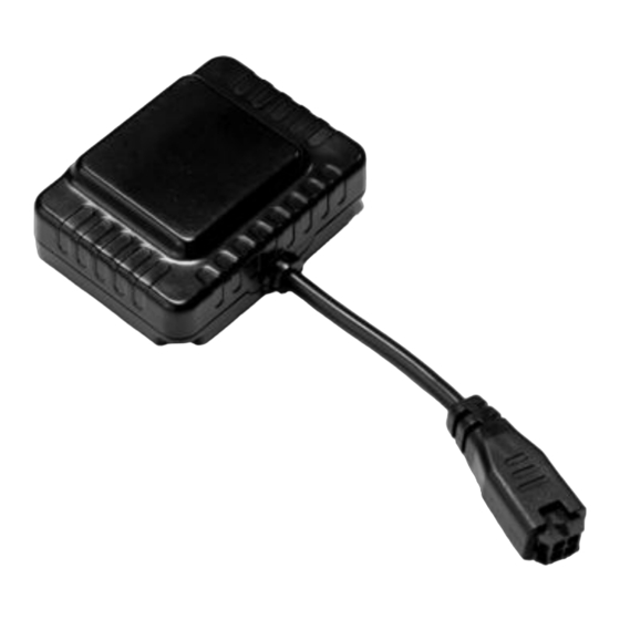
Page 6: Data Cable Connection
1.4. D-1X Connection The step to connect a D-1X tracker, is to find the plug on the other side of cable. Then, insert the plug into D-1X’s jack. Once D-1X has power, the LEDs will begin to blink. It is means your components are correctly connected. -
Page 7: Setting Cellular Services Provider Number
Visit LOCOSYS cloud platform http://console.wisegps.cn/, filling the user name and password. Note. Get the login account from your provider. Figure 7 If there are are any problem with uploading data from your D-1X to the cloud platform. Please refer to the troubleshooting section. Page 7 of 25... -
Page 8: Vehicle Online Admin System
Map zoom control: changes map zoom level. Drawing control: draw a circle or a polygon for geofence setting. 6) Maps Allow to change currently used Google map view or satellite view. Page 8 of 25 © 2017 LOCOSYS Technology Inc. - Page 9 Fence (Please refer to section 2.3.5) Idle: Open idle list and check idle data. (Only for D-11) Photo: Open image manager and check image data when tracker has installed camera. Page 9 of 25 © 2017 LOCOSYS Technology Inc.
-
Page 10: Management
Import device (Please refer section 2.2.2) Add vehicle (Please refer section 2.2.3) 4) Group object detail panel 5) Object detail operation Edit device infomation Figure 11 Change Parent Page 10 of 25 © 2017 LOCOSYS Technology Inc. - Page 11 Customer management is an approach to manage a lot of tracking devices. It’s allows user to create user sub accounts and manage their user roles. Note: user roles with different rights must be created first. Figure 13 Figure 14 Page 11 of 25 © 2017 LOCOSYS Technology Inc.
- Page 12 GPS status. It’s allows user to import a new device when you get a tracker with their terminal ID. Figure 15 You can click “Import” blue button to add a new physical device into system. Figure 16 Page 12 of 25 © 2017 LOCOSYS Technology Inc.
- Page 13 Figure 17 You can click “Add” blue control button to create new vehicle object into system. Figure 18 Figure 19 Page 13 of 25 © 2017 LOCOSYS Technology Inc.
-
Page 14: Monitor
ACC On/Off, important notifications, change map type, vehicle controls and etc. Figure 20 You also can click vehicle control button”Trace”, enter real time tracing mode. Figure 21 Page 14 of 25 © 2017 LOCOSYS Technology Inc. - Page 15 20F.-13, No.79, Sec. 1, Xintai 5th Rd., Xizhi District, New Taipei City 221, Taiwan 886-2-8698-3698 886-2-8698-3699 www.locosystech.com/ Vehicle Status: Run/Stop - Green Car Offline - Gray Car Alert - Red Car Figure 22 Page 15 of 25 © 2017 LOCOSYS Technology Inc.
- Page 16 It is also could replay any journey taken by any tracker in your system. Figure 23 Select desired vehicle, time interval and display type. Then click “Query” control button. You also can click green button to get detail information. Figure 24 Page 16 of 25 © 2017 LOCOSYS Technology Inc.
- Page 17 Vehicle Name Terminal ID Alert type Over speed alert Cut power alert Enter Geo alert Exit Geo alert Vibration alert (Only for D-11) Page 17 of 25 © 2017 LOCOSYS Technology Inc.
- Page 18 It will help to analyze big amount of data of entire vehicle group. Stat Report Figure 27 Alert report Figure 28 Page 18 of 25 © 2017 LOCOSYS Technology Inc.
- Page 19 The main reason to have geofences is to control whether the units stays within it or not, so that when the geofencing unit enters or exits the area a system online notification is generated. Polygon Geofence Figure 29 Circle Geofence Figure 30 Page 19 of 25 © 2017 LOCOSYS Technology Inc.
- Page 20 Step1. Select desired geofence and click list control button. Figure 31 Step2. Remove check from “Binded” and view all not “Binded” vehicle. Figure 32 Step3. Check desired “Binded” vehicle and click Bind button. Figure 33 Page 20 of 25 © 2017 LOCOSYS Technology Inc.
- Page 21 886-2-8698-3699 www.locosystech.com/ Step4. Select action type “In”, “Out” or “In&Out” and click save button. Figure 34 Step5. Check geofence “Bind” number. It should be increment after “Bind” operation. Figure 35 Page 21 of 25 © 2017 LOCOSYS Technology Inc.
- Page 22 Set Arm Interval: set updating period in a given time interval. Overspeed: set overspeed limit value for tracker. Restart Long setting Upgrade 4) Parameters Page 22 of 25 © 2017 LOCOSYS Technology Inc.
-
Page 23: System
Xizhi District, New Taipei City 221, Taiwan 886-2-8698-3698 886-2-8698-3699 www.locosystech.com/ Figure 37 2.4. System 2.4.1. Role Role setting sections allows add or change different account role settings. Figure 38 Page 23 of 25 © 2017 LOCOSYS Technology Inc. - Page 24 Xizhi District, New Taipei City 221, Taiwan 886-2-8698-3698 886-2-8698-3699 www.locosystech.com/ 2.4.2. User User setting sections allows adding or changing different account settings, roles and personal information. Figure 39 Page 24 of 25 © 2017 LOCOSYS Technology Inc.
-
Page 25: Troubleshooting
5. Check your LEDs (both green and red) are keep blinking slowly. Note. If you connect the D-1X to external power and remove its internal battery, it is fine. But make sure the external power supply is sufficient, at least 12V/1A.