Advertisement
Quick Links
GENERAL
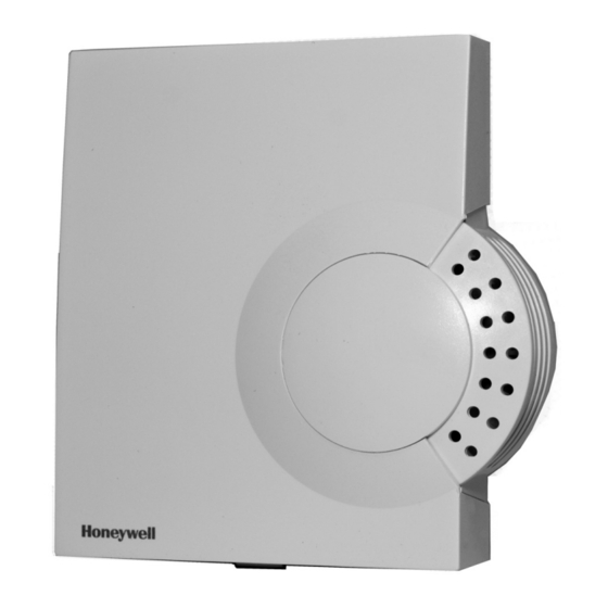
The C7110C1040 and C7110C1080 are combined CO
passive temperature wall modules designed for applications
in indoor ventilation and air conditioning systems. In con-
junction with the Honeywell controllers, they can be used to
control the flow of incoming air, thus improving air quality
while reducing energy consumption. During high-occupancy
periods, air can be supplied to rooms in order to maintain the
desired air quality, while during low-occupancy periods, the
unnecessary conditioning of air can be avoided or reduced.
FEATURES
Fully compatible with the Honeywell controllers.
CO
sensor employing state-of-the-art Non-Dispersion
2
Infrared (NDIR) technology.
Selectable CO
measurement range of 400...2000/3000
2
ppm.
Self-calibrating: automatic drift correction (ABC
algorithm) based on long-term evaluation.
Internal Service LED (visible after removing cover).
® U.S. Registered Trademark
Copyright © 2019 Honeywell Inc. All Rights Reserved
C7110C1040 and C7110C1080
MODELS
order no.
C7110C1040
C7110C1080
DIMENSIONS
/
2
WALL MODULES
PRODUCT DATA
description
0...10 VDC CO
sensor output
2
PT1000 temp. sensor (passive)
Service LED (accessible after lifting
cover)
0...10 VDC CO
sensor output
2
NTC20kΩ temp. sensor (passive)
Service LED and Occupancy Bypass
Button (accessible after lifting cover)
99
Fig. 1. Dimensions in mm
EN0B-0775GE51 R0619
30
Advertisement

Related Manuals for Honeywell C7110C1040


Summary of Contents for Honeywell C7110C1040
- Page 1 In con- junction with the Honeywell controllers, they can be used to control the flow of incoming air, thus improving air quality while reducing energy consumption. During high-occupancy...
-
Page 2: Technical Data
C7110C1040 AND C7110C1080 WALL MODULES – PRODUCT DATA TECHNICAL DATA 1. Remove the cover (see Fig. 2). 2. Mount the socket onto the wall approx. 1.5 meters above General the floor. Power supply (terminals 24 VAC ± 20%; 50/60 Hz or 3. - Page 3 VOLTAGE VOLTAGE After initiating the desired calibration process by removing Fig. 4. Wiring C7110C1040 / 1080 to controller and power and then repositioning the jumper, restore power and separate safety transformer then wait until the calibration process has been completed (see "Behavior of Service LED during Quick Calibration")
- Page 4 C7110C1040 AND C7110C1080 WALL MODULES – PRODUCT DATA Zero Calibration ("CAL0") When the configuration jumper is set to the factory default position of "2000" ppm or to "3000" ppm, the wall module will operate normally and perform ABC. Fig. 6. Jumper set to CAL0 When the configuration jumper is set to position "CAL0"...
-
Page 5: Service Led
C7110C1040 AND C7110C1080 WALL MODULES – PRODUCT DATA "DEBUG" Fig. 10. Do not set jumper set to DEBUG! DO NOT USE! Configuration Potentiometer The wall module features a configuration potentiometer (accessible only after removing the top cover) which can be... - Page 6 C7110C1040 AND C7110C1080 WALL MODULES – PRODUCT DATA The "Sensor Output" Mode The "Relay Output" Mode In the "Sensor Output" mode (analog), the Service LED (see In the "Relay Output" mode (digital), the Service LED (see Fig. 11) is always dark.
- Page 7 C7110C1040 AND C7110C1080 WALL MODULES – PRODUCT DATA LED BEHAVIORS AND MEANINGS Table 1. Service-LED behaviors and their meanings service LED modes remarks "Sensor Output" (S.O.) + 1 flash / sec for "Relay Output" (R.O.) Calibration warm-up 90 sec modes...
-
Page 8: Connection Terminals
CONNECTION Fig. 14. Mounting the T7460-LONJACK Manufactured for and on behalf of the Connected Building Division of Honeywell Products and Solutions SARL, Z.A. La Pièce, 16, 1180 Rolle, Switzerland by its Authorized Representative: Home and Building Technologies Honeywell GmbH Böblinger Strasse 17...