
Related Manuals for Barco R9841810


Summary of Contents for Barco R9841810
- Page 1 Universal Lamp Replacement Kit Installation manual For SLM *8/*10 and R9+/R12+ projectors R9841810 R5976544/02 04/01/2005...
- Page 2 Barco nv Events Noordlaan 5, B-8520 Kuurne Phone: +32 56.36.89.70 Fax: +32 56.36.88.24 E-mail: events@barco.com Visit us at the web: www.barco.com Printed in Belgium...
-
Page 3: Safety Warnings
1.2 Product care Installation Kit The universal lamp replacement Kit R9841810 is designed for use ONLY with the BARCO SLM G8/R8, G10/R10, R9+ and R12+ series projectors. Replacement parts When replacement parts are required, be sure the service technician has used original Barco replacement parts or authorized re- placement parts which have the same characteristics as the Barco original part. - Page 4 1. Safety Warnings R5976544 UNIVERSAL LAMP REPLACEMENT KIT 04/01/2005...
-
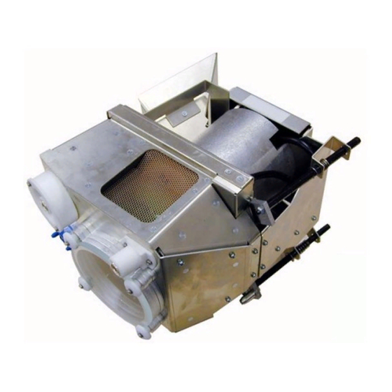
Page 5: Content Of The Kit
2. Introduction 2. INTRODUCTION 2.1 Content of the kit Content of the kit The lamp kit consists in a lamp housing, Xenon lamp included. That means that the lamp position is factory calibrated following the X- ,Y- and Z-axis. When observing a decrease in light output during the run time of the lamp, ONLY a realignment following the Z-axis can solve the light output decrease. - Page 6 2. Introduction R5976544 UNIVERSAL LAMP REPLACEMENT KIT 04/01/2005...
- Page 7 3. Removing the old lamp 3. REMOVING THE OLD LAMP 3.1 Access to the Lamp Unit. What has to be done To access the lamp casing, a side panel has to be removed. Necessary tools A flatblade screwdriver of 5 mm Removing the side panel 1.
-
Page 8: Removing The Lamp Unit
3. Removing the old lamp 3.2 Removing the Lamp Unit. What has to be done The lamp unit has to be slid out of the projector frame. Necessary tools Flatblade screwdriver of 5mm or Nutdriver of 8mm. Sliding out the lamp unit 1. - Page 9 4. Inserting the new lamp Unit 4. INSERTING THE NEW LAMP UNIT 4.1 Installation of the new Lamp Unit. What has to be done First remove the lock nut on each spacer screw and next slide the lamp unit into the projector frame. Necessary tools Flatblade screwdriver of 5mm or Nut driver 8mm Installing the lamp unit...
- Page 10 4. Inserting the new lamp Unit Image 4-2 Lamp unit mounting 3. Secure the position of the lamp unit with the 3 spacer screws. Image 4-3 Lamp unit fixation 4.2 Optical Alignment of the lamp What may be adjusted!! The adjustments to the Y-axis and X-axis (balancing the light intensity) are FACTORY PREADJUSTED. Consequently, both ad- justable screws are anchored by a lock screw and sealed with a warranty label (Destroying the label void the warranty).
- Page 11 4. Inserting the new lamp Unit Factory Preadjusted Image 4-4 Optical alignments scews Necessary tools • Allen Key 3mm • nut driver 10mm How to adjust Optical alignment of the lamp to the z-axis, follow the next procedure: 1. Put a lightmeter in the center of the screen. 2.
-
Page 12: Reinstalling The Side Panel
4. Inserting the new lamp Unit 4.3 Reinstalling the Side Panel What has to be done After the new lamp unit has been installed, the side panel has to be remounted. Necessary tools A flatblade screwdriver of 5 mm Reinstalling the side panel 1.