Table of Contents
Advertisement
Quick Links
Advertisement
Table of Contents

Related Manuals for Supermicro H12SSG-AN6


Summary of Contents for Supermicro H12SSG-AN6
- Page 1 H12SSG-AN6 USER’S MANUAL Revision 1.0a...
- Page 2 State of California, USA. The State of California, County of Santa Clara shall be the exclusive venue for the resolution of any such disputes. Supermicro's total liability for all claims will not exceed the price paid for the hardware product.
- Page 3 It provides information for the installation and use of the H12SSG-AN6 motherboard. About This Motherboard Built upon the functionality and capability of the EPYC 7002/7003* processor, the H12SSG-AN6 motherboard provides superior graphics capability and system performance while consuming little power. Please note that this motherboard is intended to be installed and serviced by professional technicians only.
- Page 4 H12SSG-AN6 User's Manual Contacting Supermicro Headquarters Address: Super Micro Computer, Inc. 980 Rock Ave. San Jose, CA 95131 U.S.A. Tel: +1 (408) 503-8000 Fax: +1 (408) 503-8008 Email: marketing@supermicro.com (General Information) support@supermicro.com (Technical Support) Website: www.supermicro.com Europe Address: Super Micro Computer B.V.
-
Page 5: Table Of Contents
Preface Table of Contents Chapter 1 Introduction 1.1 Quick Reference .........................10 Quick Reference Table ......................11 Motherboard Features .......................12 Chipset Block Diagram......................14 1.2 Processor and Chipset Overview ..................15 1.3 Special Features ........................15 Recovery from AC Power Loss ..................15 1.4 System Health Monitoring ....................16 Onboard Voltage Monitors ....................16 Fan Status Monitor with Firmware Control ...............16 Environmental Temperature Control .................16... - Page 6 H12SSG-AN6 User's Manual 2.7 Jumper Settings .........................37 How Jumpers Work ......................37 2.8 LED Indicators ........................39 Chapter 3 Troubleshooting 3.1 Troubleshooting Procedures ....................41 Before Power On ......................41 No Power ..........................41 No Video ...........................42 System Boot Failure ......................42 Memory Errors ........................42 The System Can't Retain the Setup Configuration ............42 When the System Becomes Unstable ................43...
- Page 7 Appendix B Standardized Warning Statements B.1 Battery Handling .........................86 B.2 Product Disposal .........................88 Appendix C UEFI BIOS Recovery C.1 Overview ..........................89 C.2 Recovering the UEFI BIOS Image ..................89 C.3 Recovering the BIOS Block with a USB Device ..............89...
-
Page 8: Chapter 1 Introduction
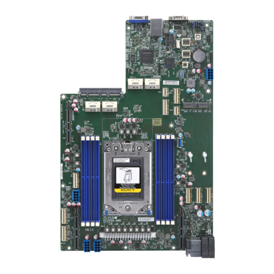
• Product safety info: https://www.supermicro.com/about/policies/safety_information.cfm • If you have any questions, please contact our support team at: support@supermicro.com This manual may be periodically updated without notice. Please check the Supermicro website for possible updates to the manual revision level. - Page 9 Chapter 1: Introduction Figure 1-1. H12SSG-AN6 Image...
-
Page 10: Quick Reference
2280 USB13 MH17 MH16 22110 22110 MH19 JPCIE7 JPWR3 JSXB3-1 JPCIE9 BAR CODE BAR CODE MAC CODE MAC CODE H12SSG-AN6 REV:1.00 DIMME1 DIMMF1 DIMMG1 DIMMH1 DIMMD1 DIMMC1 DIMMB1 DIMMA1 JPCIE8 JMP2 JMP1 JMP3 JPWR2 JPWR1 JMP3 Figure 1-2. H12SSG-AN6 Layout... -
Page 11: Quick Reference Table
Chapter 1: Introduction Quick Reference Table Jumper Description Default Setting JBT1 Clear CMOS Open (Normal) JWD1 Watch Dog control Pins 1-2 (Reset) Description Status M.2-B1 Active LED On: Activity on M.2-B1 device M.2-A1 Active LED On: Activity on M.2-A1 device LED1 UID LED Solid Blue: UID Activated... -
Page 12: Motherboard Features
H12SSG-AN6 User's Manual Motherboard Features Features • Single EPYC 7002/7003 Processor, in one SP3 socket Memory • Up to 2TB registered ECC DDR4 up to 3200MHz in eight DIMM slots DIMM Size • Up to 256GB size at 1.2V Chipset •... - Page 13 Chapter 1: Introduction Features • Onboard voltage monitoring for +1.8V, 3.3V, +5V, +12V, +3.3V Standby, +5V Standby, VBAT, HT, Memory • Onboard monitoring for CPU, system, and memory temperature • CPU switching phase voltage regulator • CPU Thermal Trip support Fan Control •...
-
Page 14: Chipset Block Diagram
H12SSG-AN6 User's Manual Chipset Block Diagram 01 Block Diagram------- H12SSG-AN6 AMD SP3 Rome Rev. 1.00 02 SMBus Diagram------- 03 Power Rail Diagram-- 04 Clock Tree Diagram-- 05 Reset Diagram------- 06 P0-MEM_CH_A_B------- 07 P0-MEM_CH_C_D------- 08 P0-MEM_CH_E_F------- 09 P0-MEM_CH_G_H------- JAIOM1 10 P0-DIMM-CH-A--------... -
Page 15: Processor And Chipset Overview
• System Management Bus (SMBus) Specification Version 3.1.1 1.3 Special Features This section describes the health monitoring features of the H12SSG-AN6. The motherboard has an onboard System Hardware Monitor chip that supports system health monitoring. Recovery from AC Power Loss The Basic I/O System (BIOS) provides a setting that determines how the system will respond when AC power is lost and then restored to the system. -
Page 16: System Health Monitoring
H12SSG-AN6 User's Manual 1.4 System Health Monitoring This section describes the health monitoring features of the H12SSG-AN6 motherboard. The motherboard has an onboard Baseboard Management Controller (BMC) chip that supports system health monitoring. Once a voltage becomes unstable, a warning is given or an error message is sent to the screen. -
Page 17: Acpi Features
Chapter 1: Introduction 1.5 ACPI Features ACPI stands for Advanced Configuration and Power Interface. The ACPI specification defines a flexible and abstract hardware interface that provides a standard way to integrate power management features throughout a computer system including its hardware, operating system and application software. -
Page 18: Chapter 2 Installation
H12SSG-AN6 User's Manual Chapter 2 Installation 2.1 Static-Sensitive Devices Electrostatic Discharge (ESD) can damage electronic com ponents. To prevent damage to your motherboard, it is important to handle it very carefully. The following measures are generally sufficient to protect your equipment from ESD. -
Page 19: Motherboard Installation
Chapter 2: Installation 2.2 Motherboard Installation All motherboards have standard mounting holes to fit different types of chassis. Make sure that the locations of all the mounting holes for both the motherboard and the chassis match. Although a chassis may have both plastic and metal mounting fasteners, metal ones are highly recommended because they ground the motherboard to the chassis. - Page 20 H12SSG-AN6 User's Manual Figure 2-1. Motherboard Mounting Holes...
-
Page 21: Installing The Motherboard
Chapter 2: Installation Installing the Motherboard 1. Install the I/O shield into the back of the chassis. 2. Locate the mounting holes on the motherboard. See the previous page for the locations. 3. Locate the matching mounting holes on the chassis. Align the mounting holes on the motherboard with the mounting holes on the chassis. -
Page 22: Processor And Heatsink Installation
CPU socket cap is in place and none of the socket pins are bent; otherwise, contact your retailer immediately. • Refer to the Supermicro website for updates on CPU support. Installing the Processor and Heatsink 1. Unscrew the screws holding down Force Frame in the sequence of 3-2-1. The screws are numbered on the force frame next to each screw hole. - Page 23 Chapter 2: Installation 2. The spring-loaded force frame will raise up after the last screw securing it (#1) is removed. Gently allow it to lift up to its stopping position. 3. Lift the rail frame up by gripping the lift tabs near the front end of the rail frame. While keeping a secure grip of the rail frame, lift it to a position so you can do the next step of removing the external cap.
- Page 24 H12SSG-AN6 User's Manual 4. Remove the external cap from the Rail Frame by pulling it upwards through the rail guides on the rail frame. External Cap PnP Cover Cap 5. The CPU package is shipped from the factory with the blue carrier frame pre-assembled.
- Page 25 Chapter 2: Installation Note: You can only install the CPU inside the socket in one direction with the handle at the top. Make sure that it is properly inserted into the CPU socket before closing the rail frame plate. If it doesn't close properly, do not force it as it may damage your CPU. Instead, open the rail frame plate again, and double-check that the CPU is aligned properly.
- Page 26 H12SSG-AN6 User's Manual 9. Gently lower the force frame down onto the rail frame and hold it in place until it is seated in the Socket housing. Note that the force frame is spring loaded and has to be held in place before it is secured. Important: Use a torque screwdriver, set it at 16.1 kgf-cm (14.0 lbf-in) with a Torx T20 screw head bit, to prevent damage to the CPU.
- Page 27 Chapter 2: Installation 11. After the force frame is secured and the CPU package is in place, now you must install the heatsink to the frame. Lower the heatsink down till it rests securely over the four screw holes on CPU package on the socket frame. 12.
-
Page 28: Memory Support And Installation
Memory Support The H12SSG-AN6 supports up to 4TB of ECC DDR4 3200 MHz speed, SDRAM memory in eight slots. Refer to the table below for additional memory information. Notes: Check the Supermicro website for possible updates to memory support. - Page 29 Chapter 2: Installation Populating RDIMM/RDIMM 3DS/LRDIMM/LRDIMM 3DS DDR4 Memory Modules Maximum DIMM Capacity (GB) Maximum Type DIMM Population Frequency (MHz) 1 Channel 8 Channels 1R (1 Rank) 32GB 256GB 3200 RDIMM 2R or 2DR (2 Ranks) 64GB 512GB 3200 LRDIMM dual die 4DR (4 Ranks) 128GB 3200...
-
Page 30: Dimm Module Population
JCPLD1 H12SSG-AN6 User's Manual JPWR4 JPCIE6 JPCIE5 DIMM Module Population There is no specific order or sequence required when installing memory modules. However do keep the following in mind: AIOM1 • Mixed DIMM speeds can be installed. However, all DIMMs will run at the speed of the... -
Page 31: Dimm Installation
Chapter 2: Installation DIMM Installation 1. Insert the desired number of DIMMs into the memory slots, there is no specific sequence or order required Receptive 2. Push the release tabs outwards on both Point ends of the DIMM slot to unlock it. 3. -
Page 32: Rear I/O Ports
H12SSG-AN6 User's Manual 2.5 Rear I/O Ports See Figure 2-1 below for the locations and descriptions of the various I/O ports on the rear of the motherboard. Figure 2-2. I/O Port Locations and Definitions Rear I/O Ports Description Description COM Port USB Ports (USB3.1) - Page 33 See 2.6 for the front panel UID LED header location on JF1. Note: UID can also be triggered via IPMI on the serverboard. For more information on IPMI, please refer to the IPMI User's Guide posted on our website at http://www.supermicro.com...
-
Page 34: Connectors
H12SSG-AN6 User's Manual 2.6 Connectors M.2 Slots (JM2_A1, JM2_B1) The M.2 slots are for Solid State Devices (SSDs) that conform to the PCIe M.2 specifications (formerly known as NGFF). These M.2 slots supports M-Key PCIe 4.0 storage cards with form factors of 2242, 2260, 2280, and 22110. - Page 35 USB3_TP AIOM Slot The Supermicro Advanced I/O Module (AIOM) PCIe 4.0 x16 slot (AIOM1) can be utilized to offer additional LAN ports, VPU, storage devices, etc. on the motherboard. Please visit the Supermicro website for all available module options. Also, please note that it is mandatory to unplug power cords prior to removing or installing an AIOM module card.
- Page 36 H12SSG-AN6 User's Manual GPU 12V 8-pin Power Connectors (JPWR1 - JPWR4) JPWR1, JPWR2, JPWR3, and JPWR4 are all 8-pin 12V DC power inputs for GPUs that have been installed in the system's PCIe slots. Refer to the table below for pin definitions.
-
Page 37: Jumper Settings
Chapter 2: Installation 2.7 Jumper Settings How Jumpers Work To modify the operation of the motherboard, jumpers can be used to choose between optional settings. Jumpers create shorts between two pins to change the function of the connector. Pin #1 is identified with a thicker border line on the printed circuit board. See the diagram below for an example of jumping pins 1 and 2. - Page 38 H12SSG-AN6 User's Manual Watch Dog (JWD1) JWD1 controls the Watch Dog function. Watch Dog is a monitor that can reboot the system when a software application hangs. Jumping pins 1-2 will cause Watch Dog to reset the system if an application hangs. Jumping pins 2-3 will generate a non-maskable interrupt signal for the application that hangs.
-
Page 39: Led Indicators
Chapter 2: Installation 2.8 LED Indicators IPMI LAN Port LEDs The IPMI LAN port has two LED indicators. The Activity LED is green and indicates connection and activity. The Link LED may be green, orange/amber, or off to indicate the speed of the connection. - Page 40 H12SSG-AN6 User's Manual UID LED Indicator (LED1) The rear LED1 is located next to the UID switch. The front UID LED is located on the front panel. When you press the UID switch, both rear LED1 and front UID LED indicators will turn on.
-
Page 41: Chapter 3 Troubleshooting
Chapter 3: Troubleshooting Chapter 3 Troubleshooting 3.1 Troubleshooting Procedures Use the following procedures to troubleshoot your system. If you have followed all of the procedures below and still need assistance, refer to the ‘Technical Support Procedures’ and/ or ‘Returning Merchandise for Service’ section(s) in this chapter. Always disconnect the AC power cord before adding, changing or installing any non hot-swap hardware components. -
Page 42: No Video
H12SSG-AN6 User's Manual No Video 1. If the power is on but you have no video, remove all the add-on cards and cables. 2. Set JPG1 to [1-2] and check if you follow the guidelines to install the memory module. -
Page 43: When The System Becomes Unstable
2. Memory support: Make sure that the memory modules are supported by testing the modules using memtest86 or a similar utility. Note: Refer to the product page on our website at http:\\www.supermicro.com for memory and CPU support and updates. 3. HDD support: Make sure that all hard disk drives (HDDs) work properly. Replace the bad HDDs with good ones. -
Page 44: Technical Support Procedures
H12SSG-AN6 User's Manual 4. Identifying bad components by isolating them: If necessary, remove a component in question from the chassis, and test it in isolation to make sure that it works properly. Replace a bad component with a good one. -
Page 45: Frequently Asked Questions
3.3 Frequently Asked Questions Question: What type of memory does my motherboard support? Answer: The H12SSG-AN6 motherboard supports up to 2TB registered ECC DDR4 up to 3200MHz memory in eight slots. See Section 2.4 for details on installing memory. Question: How do I update my BIOS? Answer: It is recommended that you do not upgrade your BIOS if you are not experiencing any problems with your system. -
Page 46: Returning Merchandise For Service
H12SSG-AN6 User's Manual 3.4 Returning Merchandise for Service A receipt or copy of your invoice marked with the date of purchase is required before any warranty service will be rendered. You can obtain service by calling your vendor for a Returned Merchandise Authorization (RMA) number. -
Page 47: Proper Battery Disposal
Chapter 3: Troubleshooting Proper Battery Disposal Please handle used batteries carefully. Do not damage the battery in any way; a damaged battery may release hazardous materials into the environment. Do not discard a used battery in the garbage or a public landfill. Please comply with the regulations set up by your local hazardous waste management agency to dispose of your used battery properly. -
Page 48: Chapter 4 Bios
BIOS 4.1 Introduction This chapter describes the AMIBIOS™ Setup utility for the H12SSG-AN6 motherboard. The BIOS is stored on a chip and can be easily upgraded using a flash program. Note: Due to periodic changes to the BIOS, some settings may have been added or deleted and might not yet be recorded in this manual. -
Page 49: Main Setup
Note: The time is in the 24-hour format. For example, 5:30 P.M. appears as 17:30:00. The date's default value is 01/01/2015 after RTC reset. Supermicro H12SSG-AN6 BIOS Version This item displays the version of the BIOS ROM used in the system. - Page 50 H12SSG-AN6 User's Manual CPLD Version This item displays the CPLD version of the BIOS ROM used in the system. Memory Information Total Memory This item displays the total size of memory available in the system.
-
Page 51: Advanced
Chapter 4: BIOS 4.3 Advanced Use the arrow keys to select Boot Setup and press <Enter> to access the submenu items. Warning: Take caution when changing the Advanced settings. An incorrect value, a very high DRAM frequency, or an incorrect DRAM timing setting may make the system unstable. - Page 52 H12SSG-AN6 User's Manual Bootup NumLock State Use this feature to set the Power on state for the <Numlock> key. The options are On and Off. Wait For "F1" If Error Use this feature to force the system to wait until the 'F1' key is pressed if an error occurs.
- Page 53 Chapter 4: BIOS Trusted Computing Configuration Security Device Support Enables or disables BIOS support for secuirty device. OS will not show Security Device. TCG EFI protocol and INT1A interface will not be available. The options are Disabled and Enabled. Disable Block Sid Override to allow SID authentication in TCG storage device.
- Page 54 H12SSG-AN6 User's Manual Super IO Configuration The following Super IO information will display: • Super IO Chip AST2600 Serial Port 1 Configuration Serial Port Select Enabled to enable the selected onboard serial port. The options are Disabled and Enabled. Device Settings This item displays the status of a serial part specified by the user.
- Page 55 Chapter 4: BIOS Serial Port Console Redirection COM1 Console Redirection Select Enabled to enable console redirection support for a serial port specified by the user. The options are Enabled and Disabled. *If the item above set to Enabled, the following items will become available for user's configuration: Console Redirection Settings Terminal Type...
- Page 56 H12SSG-AN6 User's Manual Flow Control Use this feature to set the flow control for Console Redirection to prevent data loss caused by buffer overflow. Send a "Stop" signal to stop sending data when the receiving buffer is full. Send a "Start" signal to start sending data when the receiving buffer is empty. The options are None and Hardware RTS/CTS.
- Page 57 Chapter 4: BIOS and function key support. Select ANSI to use the Extended ASCII Character Set. Select VT-UTF8 to use UTF8 encoding to map Unicode characters into one or more bytes. The options are VT100, VT100+, VT-UTF8, and ANSI. Bits per second Use this feature to set the transmission speed for a serial port used in Console Redirection.
- Page 58 H12SSG-AN6 User's Manual Resolution 100x31 Select Enabled for extended-terminal resolution support. The options are Disabled and Enabled. Putty KeyPad This feature selects the settings for Function Keys and KeyPad used for Putty, which is a terminal emulator designed for the Windows OS. The options are VT100, LINUX, XTERMR6, SC0, ESCN, and VT400.
- Page 59 Chapter 4: BIOS Flow Control Use this item to set the flow control for Console Redirection to prevent data loss caused by buffer overflow. Send a "Stop" signal to stop sending data when the receiving buffer is full. Send a "Start" signal to start sending data when the receiving buffer is empty. The options are None, Hardware RTS/CTS, and Software Xon/Xoff.
- Page 60 H12SSG-AN6 User's Manual SEV ASID Count This field specifies the maximum valid ASID, which affects the maximum system physical address space. The options are 253 ASIDs, 509 ASIDs, and Auto. SEV-ES ASID Space Limit Control Auto or Manual to control SEV-ES ASID Space Limit. The options are Auto and Manual.
- Page 61 Chapter 4: BIOS ACS Enable AER must be enabled for ACS to work. Options are Enabled, Disabled, and Auto. Package Power Limit Control Set to Auto to use the fused PPT or Manual to allow the user to set a customized PPT. APBDIS Use this setting to .
- Page 62 H12SSG-AN6 User's Manual DDR Power Down Enable Use this setting to control DDR Power Down Enable. Options include Disabled, Enabled, and Auto. CPU1 Memory Information Provides information on CPU1 DIMMs. AMI Graphic Output Protocol Policy User select monitor output by graphic output protocol.
- Page 63 Chapter 4: BIOS No Snoop Use this setting to Enable or Disable PCI Express Device No Snoop option. VGA Priority Use this setting to select between onboard or offboard VGA support The options are Onboard and Offboard. NVMe Firmware Source Use this setting to select between the AMI Native firmware support or the device vendor- defined firmware support.
- Page 64 H12SSG-AN6 User's Manual Network Stack Configuration Network Stack This setting allows you to Enable or Disable the UEFI Network Stack. IPv4 PXE Support This setting allows you to Enable or Disable IPv4 PXE boot support. If disabled, IPv4 PXE boot support will not be available.
- Page 65 Chapter 4: BIOS SATA Configuration SATA Information SATA Enable Use this setting to disable or enable OnChip SATA controller. Options are Disabled, Enabled, and Auto. SATA Hotplug Use this setting to disable or enable OnChip SATA Hotplug function. Options are Disabled and Enabled.
- Page 66 H12SSG-AN6 User's Manual Client Private Key Entroll factory defaults or load the KMS TLS certificates from the file. Options include Update, Delete, and Export. HTTB Boot Configuration HTTP Boot Configuration HTTP Boot Policy Sets the HTTP boot policy to Appply to all LANs, Apply to each LAN, and Boot Priority #1 instantly.
- Page 67 Chapter 4: BIOS iSCSI Configuration iSCSI Initiator Name This feature allows the user to enter the unique name of the iSCSI Initiator in IQN format. Once the name of the iSCSI Initiator is entered into the system, configure the proper settings for the following items.
- Page 68 H12SSG-AN6 User's Manual Enroll Certification Using File Use this feature to enroll certification from a file. Certification GUID Use this feature to input the certification GUID. Commit Changes and Exit Use this feature to save all changes and exit TLS settings.
-
Page 69: Ipmi
Chapter 4: BIOS 4.4 IPMI This tab allows you to configure the following IPMI settings for the system. Use this feature to configure Intelligent Platform Management Interface (IPMI) settings. BMC Firmware Revision This item indicates the IPMI firmware revision used in your system. IPMI Status This item indicates the status of the IPMI firmware installed in your system. - Page 70 H12SSG-AN6 User's Manual System Event Log Enabling/Disabling Options SEL Components Select Enabled for all system event logging at bootup. The options are Disabled and Enabled. Erasing Settings Erase SEL Select Yes, On next reset to erase all system event logs upon next system reboot. Select Yes, On every reset to erase all system event logs upon each system reboot.
- Page 71 Chapter 4: BIOS Station IP Address This item displays the Station IP address for this computer. This should be in decimal and in dotted quad form. Gateway IP Address This item displays the Gateway IP address for this computer. This should be in decimal and in dotted quad form (i.e., 172.31.0.1).
-
Page 72: Event Logs
H12SSG-AN6 User's Manual 4.5 Event Logs This tab allows the user to configure the following event logs settings for the system. Change SMBIOS Event Log Settings This feature allows the user to configure SMBIOS Event settings. Enabling/Disabling Options SMBIOS Event Log Select Enabled to enable SMBIOS (System Management BIOS) Event Logging during system boot. - Page 73 Chapter 4: BIOS When Log is Full Select Erase Immediately to immediately erase all errors in the SMBIOS event log when the event log is full. Select Do Nothing for the system to do nothing when the SMBIOS event log is full. The options are Do Nothing and Erase Immediately. SMBIOS Event Log Standard Settings Log System Boot Event Select Enabled to log system boot events.
-
Page 74: Security
H12SSG-AN6 User's Manual 4.6 Security This tab allows you to configure the following security settings for the system. Administrator Password Press Enter to create a new, or change an existing Administrator password. Note that if the Administrator Password is erased, the User Password will be cleared as well. - Page 75 Chapter 4: BIOS SMCI Security Erase Configuration This submenu allows the user to configure the following Key Management settings. Security Function This setting determines the security of the password. Options are Disable, Set Password, Security Erase - Password, Security Erase - PSID, and Security Erase - Without Passord. Password This setting allows you to set the password.
- Page 76 H12SSG-AN6 User's Manual Reset To Setup Mode Export Secure Boot variables Enroll EFI Image This allows the image to run in Secure Boot Mode, and enroll SHA256 hash of the binary into an Authorized Signature Database (db). Device Guard Ready Remoe 'UEFI CA' from DB...
- Page 77 Chapter 4: BIOS OsRecovery Signature This item uploads and installs an OSRecovery Signature. You may select options for Set New for a factory default key, or select Append to get it from a file. The file formats accepted are: 1) Public Key Certificate a.
-
Page 78: Boot
H12SSG-AN6 User's Manual 4.7 Boot Use this tab to configure Boot Settings: Boot Mode Select Use this item to select the type of device that the system is going to boot from. The options are Legacy, UEFI, and Dual. The default setting is DUAL. - Page 79 Chapter 4: BIOS Delete Boot Option Use this feature to remove a pre-defined boot device from which the system will boot during startup. The settings are [any pre-defined boot device]. UEFI Hard Disk Drive BBS Priorities This feature allows the user to specify which UEFI devices are boot devices. •...
-
Page 80: Save & Exit
H12SSG-AN6 User's Manual 4.8 Save & Exit Select the Save & Exit tab to enter the Save & Exit BIOS Setup screen. Discard Changes and Exit Select this option to quit the BIOS Setup without making any permanent changes to the system configuration, and reboot the computer. - Page 81 Chapter 4: BIOS Default Options Restore Optimized Defaults To set this feature, select Restore Defaults from the Save & Exit menu and press <Enter>. These are factory settings designed for maximum system stability, but not for maximum performance. Save as User Defaults To set this feature, select Save as User Defaults from the Exit menu and press <Enter>.
-
Page 82: Appendix A Software
USB flash or media drive, or the IPMI KVM console. 2. Go to the Supermicro web page for your motherboard and click on "Download the Latest Drivers and Utilities", select the proper driver, and copy it to a USB flash or media drive. - Page 83 Appendix A: Software 4. During Windows Setup, continue to the dialog where you select the drives on which to install Windows. If the disk you want to use is not listed, click on “Load driver” link at the bottom left corner. Figure A-2.
-
Page 84: Driver Installation
The Supermicro website contains drivers and utilities for your system at https://www. supermicro.com/wdl/driver. Some of these must be installed, such as the chipset driver. After accessing the website, go into the CDR_Images (in the parent directory of the above link) and locate the ISO file for your motherboard. Download this file to a USB flash oe media drive. -
Page 85: Superdoctor ® 5
A.3 SuperDoctor ® The Supermicro SuperDoctor 5 is a program that functions in a command-line or web-based interface for Windows and Linux operating systems. The program monitors such system health information as CPU temperature, system voltages, system power consumption, fan speed, and provides alerts via email or Simple Network Management Protocol (SNMP). -
Page 86: Appendix B Standardized Warning Statements
The following statements are industry standard warnings, provided to warn the user of situations which have the potential for bodily injury. Should you have questions or experience difficulty, contact Supermicro's Technical Support department for assistance. Only certified technicians should attempt to install or configure components. - Page 87 Appendix B: Warning Statements Attention Danger d'explosion si la pile n'est pas remplacée correctement. Ne la remplacer que par une pile de type semblable ou équivalent, recommandée par le fabricant. Jeter les piles usagées conformément aux instructions du fabricant. ¡Advertencia! Existe peligro de explosión si la batería se reemplaza de manera incorrecta.
-
Page 88: Product Disposal
H12SSG-AN6 User's Manual B.2 Product Disposal Warning! Ultimate disposal of this product should be handled according to all national laws and regulations. 製品の廃棄 この製品を廃棄処分する場合、 国の関係する全ての法律 ・ 条例に従い処理する必要があります。 警告 本电品的电弃处理电根据所有国家的法律和电章电行。 警告 本產品的廢棄處理應根據所有國家的法律和規章進行。 Warnung Die Entsorgung dieses Produkts sollte gemäß allen Bestimmungen und Gesetzen des Landes erfolgen. -
Page 89: Appendix C Uefi Bios Recovery
Warning: Do not upgrade the BIOS unless your system has a BIOS-related issue. Flashing the wrong BIOS can cause irreparable damage to the system. In no event shall Supermicro be liable for direct, indirect, special, incidental, or consequential damages arising from a BIOS update. - Page 90 USB flash drive with FAT16 or FAT32 format and rename the file to SUPER.ROM. Note: If you cannot locate the "SUPER.ROM" file in your driver disk, visit our website at www.supermicro.com to download the correct BIOS image into a USB flash device and rename it "SUPER.ROM".
- Page 91 SUPERMICO BIOS Update: https://www.youtube.com/watch?v=S8z6iOEHGwY * If the BIOS flash recovery fails, contact our RMA Department to have the BIOS chip reprogrammed. This will require shipping the board to Supermicro for repair. Submit your RMA request at https://www.supermicro.com/support/rma Please make sure to follow all instructions when returning the motherboard.