Table of Contents
Advertisement
Quick Links
Advertisement
Table of Contents

Related Manuals for Planet IPOE-175

Summary of Contents for Planet IPOE-175
- Page 1 Industrial IP67 1-Port 60W 802.3bt PoE++ Injector IPOE-175 User’s Manual...
-
Page 2: Table Of Contents
3.1 Installing Cable Gland with Power Cable and RJ45 UTP Cable .... 6 3.2 Connecting Waterproof Cable Kit to the Outdoor PoE Injector .... 6 3.3 Wall-mount Installation ..............9 3.4 Connecting IPOE-175 to PD ............10 3.5 Connecting IPOE-175 to PD ............10 4. Product Specifications ................12... -
Page 3: Package Contents
1. Package Contents Thank you for purchasing PLANET Industrial IP67 1-port 10/100/1000/2500T 802.3bt PoE++ Injector, IPOE-175. In the following sections, the term “Outdoor PoE Injector” means the IPOE-175. Open the box of the Industrial Ethernet Switch and carefully unpack it. The... -
Page 4: Hardware Introduction
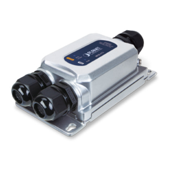
This section describes the functionalities of the outdoor PoE Injector’s components. 2.1 Product Outlook PoE- in-Use IPOE-175 Unit: mm Figure 2-1: IPOE-175 product outlook 2.2 Power Input Port Figure 2-2 shows the power input port side of the IPOE-175 Figure 2-2: Power Input Port... -
Page 5: Data Input Port And 802.3Bt Poe++ Output Port
2.3 Data Input Port and 802.3bt PoE++ Output Port Figure 2-3 shows the data input port and PoE++ output port side of the IPOE- 175. PoE++ Output Port Data Input Port Figure 2-3: Two RJ45 Ports 2.4 LED Indicators Color Function Green Indicates it has power. -
Page 6: Installation
3. Installation This section describes how to install the Outdoor PoE Injector and make connections to it. Please read the following topics and perform the procedure in the order being presented. 3.1 Installing Cable Gland with Power Cable and RJ45 UTP Cable The cable gland consists of the following: 3.2 Connecting Waterproof Cable Kit to the Outdoor PoE... - Page 7 Step 3: Insert the sealing insert into the cable gland body. Step 4: Attach the clamping nut to the cable gland to complete the cable assembly. Make sure the clamping nut is tightly attached to the cable gland body and the sealing insert is squeezed tightly.
- Page 8 40.78mm 5.00mm 11.31mm 14.00 13.72 20.18 4. Never use any waterproof cable gland that is not purchased from PLANET or doesn’t have the same dimensions of the IPOE-175; it will damage the device permanently.
-
Page 9: Wall-Mount Installation
3.3 Wall-mount Installation To install the Outdoor PoE Injector on the wall, please follow the instructions described below. Step 1: Find the wall that you want to mount the Outdoor PoE Injector on. Step 2: Refer to the picture below to screw the four screws on the wall 140.36mm Step3: Use a screwdriver to screw them into the wall. -
Page 10: Connecting Ipoe-175 To Pd
3.4 Connecting IPOE-175 to PD Users MUST complete grounding wired with the device; otherwise, a sudden lightning could cause fatal damage to the device. Earth Ground EMD (Lightning) DAMAGE IS NOT COVERED UNDER WARRANTY. 3.5 Connecting IPOE-175 to PD Step 1: Connect the additional Cat5e/6/6A cable from the PoE++ Out of the IPOE-175 to a remote PD. - Page 11 Step 3: Once the IPOE-175 detects the existence of an IEEE 802.3at/bt device or Ethernet device, the LAN LED indicator will be lit steadily, showing it is providing power. According to IEEE 802.3at/bt standard, the IPOE-175 will not inject power to the cable if not connected to a standard IEEE...
-
Page 12: Product Specifications
4. Product Specifications Product IPOE-175 Hardware Specifications Input Port 1 x 10/100/1000/2500BASE-T “Data” in RJ45 port 1 x 10/100/1000/2500BASE-T Ethernet with IEEE Output Port 802.3bt PoE++ “Data + DC” out RJ45 port Interface Input Power 1 x 2-pin terminal block Terminal - Pin 1/2 for Power (Pin 1: V+ / Pin 2: V-) - Page 13 Power over Ethernet IEEE 802.3bt PoE++ type 3 PSE PoE Standard Backward compatible with IEEE 802.3at PoE+ PoE Power 802.3btEnd-span/Mid-span Supply Type 55V DC PoE Power Max. 60 watts to 802.3bt PoE++ PD Output Max. 30 watts to 802.3at PoE+ PD 802.3bt: 1/2 (-), 3/6 (+), 4/5 (+), 7/8 (-) Power Pin End-span: 1/2 (-), 3/6 (+)
-
Page 14: Customer Support
Customer Support Thank you for purchasing PLANET products. You can browse our online FAQ resource and user’s manual on PLANET web site first to check if it could solve your issue. If you need more support information, please contact PLANET support team.