Intel R1000GL Series Quick Installation User's Manual
Hide thumbs
Also See for R1000GL Series:
- Technical product specification (76 pages) ,
- Service manual (67 pages)
Table of Contents
Advertisement
Quick Links
Intel® Server System R1000GZ/GL
Product Family
Quick Installation User's Guide
Thank you for buying an Intel® Server System. The following information will help you
assemble your Intel ® Server System and install components.
If you are not familiar with ESD [Electrostatic Discharge] procedures used during
system integration, see the complete ESD procedures described in your Service Guide.
This guide and other supporting documents are located on the web at:
http://www.intel.com/support.
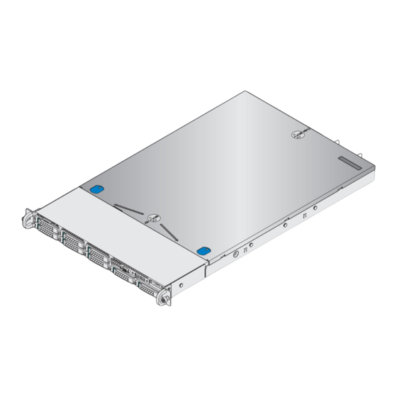
2.5" hard drive bay system as shown
*
G31060-004
Advertisement
Table of Contents

Related Manuals for Intel R1000GL Series


Summary of Contents for Intel R1000GL Series
- Page 1 Product Family Quick Installation User's Guide Thank you for buying an Intel® Server System. The following information will help you assemble your Intel ® Server System and install components. If you are not familiar with ESD [Electrostatic Discharge] procedures used during system integration, see the complete ESD procedures described in your Service Guide.
- Page 2 (This page is intentionally left blank.)
-
Page 3: Table Of Contents
Install Add-in Card Riser Assembly ................8 Install Rack Handles ......................8 Install Intel® I/O Expansion Module (optional) ............. 8 Install Intel® RAID C600 Upgrade Key (optional) ..........8 Install Intel® RAID Smart Battery (optional) ............8 Install Second Power Supply Module (optional) ..........9 Install Bezel (optional) ...................... - Page 4 Intel is a registered trademark of Intel Corporation or its subsidiaries in the United States and other countries. *Other names and brands may be claimed as the property of others. Copyright © 2012, Intel Corporation. All rights reserved.
-
Page 5: System Overview
Front Control Panel * 2.5" Hard Drive Bay system as shown Useful Information: • Riser Slot 2 is not functional without having two processors installed. • The SCU1 (4-7) port requires an Intel RAID C600 Upgrade Key installed to be functional. ®... -
Page 6: General Installation Process
General Installation Process The installation instructions in this section are for common components of Intel® Server System R1000GZ/GL Product Family. Minimum Hardware Requirements Preparing the System To avoid integration difficulties and possible board damage, your system must meet the following minimum requirements: Observe normal ESD (Electrostatic Discharge) •... -
Page 7: Install The Processor(S)
General Installation Process Install the Processor(s) A. Open the Socket Lever B. Open the Load Plate Push down the lever and slide away from the socket to Press the locking lever slightly to raise the release it. load plate. Repeat step A to release the lever on the other side. Open the load plate all the way. -
Page 8: Install Processor Heatsink(S)
Note: For additional memory configurations, see the Service Guide on the Intel Server Deployment & Management DVD that accompanied your Intel ® ® Server System, or go to: http://www.intel.com/support. Memory sizing and configuration is supported only for qualified DIMMs approved by Intel. For a list of supported memory, go to: http://serverconfigurator.intel.com. -
Page 9: Install Hard Drives
General Installation Process Install Memory Modules ... Continued To Install DIMMs: CAUTION: Avoid touching contacts Open both DIMM socket levers. when handling or installing DIMMs. Note location of alignment notch. Insert DIMM making sure the connector edge of the DIMM aligns correctly with the slot. Push down firmly on the DIMM until it snaps into place and both levers close. - Page 10 General Installation Process Install Hard Drives ... Continued 3.5" Hard Drive Carrier (For system with 3.5" hard drive bay only) Remove the drive carrier by pressing the green button and opening Remove the four screws securing the HDD interface bracket and remove the lever.
-
Page 11: Install Optical Drive
General Installation Process Install Optical Drive Install the plastic guide onto the back Insert the optical drive into chassis opening IMPORTANT NOTE: If you do not and push all the way until it stops. install a device at this location, of the drive and attach with two screws install the optical device bay filler as shown. -
Page 12: Install Add-In Card Riser Assembly
NOTE: Rack handles are required to install the Hooks (2) bezel. For detailed instructions, see the Position the riser card edge connector over product Service Guide available on the Intel ® the server board riser socket and align the Server Deployment and Management DVD. -
Page 13: Install Second Power Supply Module (Optional)
Add-in Card Slots must finish your system installation, make I/O connections, and plug in the power cord(s). 1. Verify the system top cover is installed. 2. Install the server into the rack using the instructions Intel ® RMM4 Intel ®... -
Page 14: Software
NOTE: The FRUSDR utility must be run for full platform management functionality. B. Configure your RAID Controller: If using a RAID card, use the instructions provided with the RAID controller. If using on-board RAID, you must activate RAID in the BIOS setup. See the Intel Server ®... -
Page 15: Reference
Chassis Intrusion System Fan 5 Fan 1 Fan 2 System Front Panel Fan 4 * - For server systems integrated with Intel® Server Board S2600GZ only. See your Intel Server System R1000GZ/GL Service Guide for expanded component and connection information. ®... - Page 16 Reference System Fan Connection FAN 1 FAN 2 FAN 3 FAN 4 FAN 5 FAN 6 Please find a complete list of accessories and spares at http://www.intel.com/support.
- Page 17 Reference System Cabling Diagram For system with 8 x 2.5” hard drive bay: Note: To activate the port SCU1 (4-7) on the server board, a proper Intel RAID C600 Upgrade Key must be ® installed. For instructions, see Intel RAID C600 Upgrade Key Installation Guide.
- Page 18 Reference System Cabling Diagram For system with 4 x 3.5” hard drive bay: Note: To activate the port SCU1 (4-7) on the server board, a proper Intel RAID C600 Upgrade Key must be ® installed. For instructions, see Intel RAID C600 Upgrade Key Installation Guide.
- Page 19 (This page is intentionally left blank.)
- Page 20 G31060-004...