Delta MS300 Series User Manual
Standard compact drive
Hide thumbs
Also See for MS300 Series:
- User manual (517 pages) ,
- Operation manual (56 pages) ,
- Manual (16 pages)
Table of Contents
Advertisement
Industrial Automation Headquarters
Taiwan:
Delta Electronics, Inc.
Taoyuan Technology Center
No.18, Xinglong Rd., Taoyuan District,
Taoyuan City 33068, Taiwan
TEL: +886-3-362-6301 / FAX: +886-3-371-6301
Asia
Delta Electronics ( Shanghai ) Co., Ltd.
China:
No.182 Minyu Rd., Pudong Shanghai, P.R.C.
Post code : 201209
TEL: +86-21-6872-3988 / FAX: +86-21-6872-3996
Customer Service: 400-820-9595
Japan:
Delta Electronics ( Japan ) , Inc.
Industrial Automation Sales Department
2-1-14 Shibadaimon, Minato-ku
Tokyo, Japan 105-0012
TEL: +81-3-5733-1155 / FAX: +81-3-5733-1255
Delta Electronics ( Korea ) , Inc.
Korea:
1511, 219, Gasan Digital 1-Ro., Geumcheon-gu,
Seoul, 08501 South Korea
TEL: +82-2-515-5305 / FAX: +82-2-515-5302
Delta Energy Systems ( Singapore ) Pte Ltd.
Singapore:
4 Kaki Bukit Avenue 1, #05-04, Singapore 417939
TEL: +65-6747-5155 / FAX: +65-6744-9228
Delta Electronics ( India ) Pvt. Ltd.
India:
Plot No.43, Sector 35, HSIIDC Gurgaon,
PIN 122001, Haryana, India
TEL: +91-124-4874900 / FAX: +91-124-4874945
Delta Electronics ( Thailand ) PCL.
Thailand:
909 Soi 9, Moo 4, Bangpoo Industrial Estate ( E.P.Z ) ,
Pattana 1 Rd., T.Phraksa, A.Muang,
Samutprakarn 10280, Thailand
TEL: +66-2709-2800 / FAX: +66-2709-2827
Australia:
Delta Electronics ( Australia ) Pty Ltd.
Unit 2, Building A, 18-24 Ricketts Road,
Mount Waverley, Victoria 3149 Australia
Mail: IA.au@deltaww.com
TEL: +61-1300-335-823 / +61-3-9543-3720
Americas
Delta Electronics ( Americas ) Ltd.
USA:
5101 Davis Drive, Research Triangle Park, NC 27709, U.S.A.
TEL: +1-919-767-3813 / FAX: +1-919-767-3969
Brazil:
Delta Electronics Brazil Ltd.
Estrada Velha Rio-São Paulo, 5300 Eugênio de
Melo - São José dos Campos CEP: 12247-004 - SP - Brazil
TEL: +55-12-3932-2300 / FAX: +55-12-3932-237
Mexico:
Delta Electronics International Mexico S.A. de C.V.
Gustavo Baz No. 309 Edificio E PB 103
Colonia La Loma, CP 54060
Tlalnepantla, Estado de México
TEL: +52-55-3603-9200
*We reserve the right to change the information in this manual without prior notice.
EMEA
Delta Electronics ( Netherlands ) B.V.
EMEA Headquarters:
Sales: Sales.IA.EMEA@deltaww.com
Marketing: Marketing.IA.EMEA@deltaww.com
Technical Support: iatechnicalsupport@deltaww.com
Customer Support: Customer-Support@deltaww.com
Service: Service.IA.emea@deltaww.com
TEL: +31 ( 0 ) 40 800 3900
Delta Electronics ( Netherlands ) B.V.
BENELUX:
Automotive Campus 260, 5708 JZ Helmond, The Netherlands
Mail: Sales.IA.Benelux@deltaww.com
TEL: +31 ( 0 ) 40 800 3900
Delta Electronics ( Netherlands ) B.V.
DACH:
Coesterweg 45, D-59494 Soest, Germany
Mail: Sales.IA.DACH@deltaww.com
TEL: +49 ( 0 ) 2921 987 0
Delta Electronics ( France ) S.A.
France:
ZI du bois Challand 2, 15 rue des Pyrénées,
Lisses, 91090 Evry Cedex, France
Mail: Sales.IA.FR@deltaww.com
TEL: +33 ( 0 ) 1 69 77 82 60
Delta Electronics Solutions ( Spain ) S.L.U
Iberia:
Ctra. De Villaverde a Vallecas, 265 1º Dcha Ed.
Hormigueras – P.I. de Vallecas 28031 Madrid
TEL: +34 ( 0 ) 91 223 74 20
Carrer Llacuna 166, 08018 Barcelona, Spain
Mail: Sales.IA.Iberia@deltaww.com
Delta Electronics ( Italy ) S.r.l.
Italy:
Via Meda 2–22060 Novedrate ( CO )
Piazza Grazioli 18 00186 Roma Italy
Mail: Sales.IA.Italy@deltaww.com
TEL: +39 039 8900365
Russia:
Delta Energy System LLC
Vereyskaya Plaza II, office 112 Vereyskaya str.
17 121357 Moscow Russia
Mail: Sales.IA.RU@deltaww.com
TEL: +7 495 644 3240
Delta Greentech Elektronik San. Ltd. Sti. ( Turkey )
Turkey:
Şerifali Mah. Hendem Cad. Kule Sok. No:16-A
34775 Ümraniye – İstanbul
Mail: Sales.IA.Turkey@deltaww.com
TEL: + 90 216 499 9910
Eltek Dubai ( Eltek MEA DMCC )
MEA:
OFFICE 2504, 25th Floor, Saba Tower 1,
Jumeirah Lakes Towers, Dubai, UAE
Mail: Sales.IA.MEA@deltaww.com
TEL: +971 ( 0 ) 4 2690148
DELTA_IA-MDS_MS300_UM_EN_20221125
Digitized Automation for a Changing World
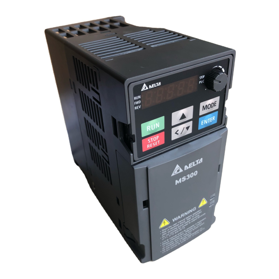
Delta Standard Compact Drive
MS300 Series User Manual
www.deltaww.com
Advertisement
Table of Contents

Related Manuals for Delta MS300 Series


Summary of Contents for Delta MS300 Series
- Page 1 Mail: Sales.IA.RU@deltaww.com TEL: +7 495 644 3240 Delta Electronics ( Americas ) Ltd. USA: Delta Greentech Elektronik San. Ltd. Sti. ( Turkey ) 5101 Davis Drive, Research Triangle Park, NC 27709, U.S.A. Turkey: TEL: +1-919-767-3813 / FAX: +1-919-767-3969 Şerifali Mah. Hendem Cad. Kule Sok. No:16-A 34775 Ümraniye –...
- Page 2 All information contained in this user manual is the exclusive property of Delta Electronics Inc. (hereinafter referred to as "Delta ") and is protected by copyright law and all other laws. Delta retains the exclusive rights of this user manual in accordance with the copyright law and all other laws. No parts in this manual may be reproduced, transmitted, transcribed, translated or used in any other ways without the prior consent of Delta.
- Page 3 READ PRIOR TO INSTALLATION FOR SAFETY. Disconnect AC input power before connecting any wiring to the AC motor drive. Even if the power has been turned off, a charge may still remain in the DC-link capacitors with hazardous voltages before the POWER LED is OFF. Do NOT touch the internal circuits and components.
- Page 4 If the motor drive generates leakage current over AC 3.5 mA or over DC 10 mA on a grounding conductor, compliance with local grounding regulations or IEC61800-5-1 standard is the minimum requirement for grounding. NOTE: The content of this manual may be revised without prior notice. Consult our distributors or download the latest version at http://www.deltaww.com/iadownload_acmotordrive...
-
Page 5: Table Of Contents
Table of Contents Introduction ............................. 1 1-1 Nameplate Information ............................2 1-2 Model Name ............................... 3 1-3 Serial Number ..............................4 1-4 Apply After Service by Mobile Device ......................... 5 1-5 RFI Jumper ................................. 6 Dimensions ............................9 2-1 Frame A ................................10 2-2 Frame B ................................ - Page 6 8-6 CMM-COP02 – Communication Extension Card, CANopen ................. 169 8-7 CMM-EC02 – Communication Extension Card, EtherCAT ................171 8-8 EMM-BPS02 -- +24V Power Extension Card ....................174 8-9 Delta Standard Fieldbus Cables ........................176 Specifications ..........................177 9-1 115V Models ..............................178 9-2 230V Models ..............................
- Page 7 Digital Input / Output Parameters ........................295 Analog Input / Output Parameters ........................321 Multi-Step Speed Parameters .........................343 Motor Parameters ............................345 Protection Parameters (1) ..........................355 Special Parameters ............................381 High-function PID Parameters .........................397 Communication Parameters ..........................415 Speed Feedback Control Parameters ......................423 Advanced Parameters .............................431 Industry Application Parameters ........................441 Protection Parameters (2) ..........................451 12-2 Adjustment &...
- Page 8 A-1 Code Description ............................782 A-2 Data Format ..............................782 A-3 Communication Protocol ..........................783 A-4 Address List ..............................788 A-5 Exception Response ............................ 794 Revision History ..........................795 Issued Edition: 00 Firmware Version: V2.01 (Refer to Pr.00-06 on the product for the firmware version.) Issued Date: 2022/11...
-
Page 10: Introduction
Chapter 1 IntroductionMS300 Introduction 1-1 Nameplate Information 1-2 Model Name 1-3 Serial Number 1-4 Apply After Service by Mobile Device 1-5 RFI Jumper... - Page 11 Chapter 1 IntroductionMS300 After receiving the AC motor drive, check for the following: Inspect the unit after unpacking to ensure that it was not damaged during shipment. Make sure that the part number printed on the package matches the part number indicated on the nameplate. Make sure that the mains voltage is within the range indicated on the nameplate.
- Page 12 Chapter 1 IntroductionMS300 1-2 Model Name For IP20 models only. Not applicable for models of 575V input voltage. Not applicable for models of 115V and 575V input voltage. For 230V input voltage (one-phase) and 460V input voltage (three-phase) models only.
- Page 13 Chapter 1 IntroductionMS300 1-3 Serial Number...
- Page 14 2. Use a smartphone to run a QR Code reader APP. 3. Point your camera at the QR Code. Hold your camera steady until the QR code comes into focus. 4. Access the Delta After Service website. 5. Fill your information into the column marked with an orange star.
-
Page 15: Rfi Jumper
Chapter 1 IntroductionMS300 1-5 RFI Jumper The drive contains Varistors / MOVs that are connected from phase to phase and from phase to ground to prevent the drive from unexpected stop or damage caused by mains surges or voltage spikes. Because the Varistors / MOVs from phase to ground are connected to ground with the RFI jumper, removing the RFI jumper disables the protection. - Page 16 Chapter 1 IntroductionMS300 Isolating main power from ground: When the power distribution system for the drive is a floating ground system (IT Systems) or an asymmetric ground system (Corner Grounded TN Systems), you must remove the RFI jumper. Removing the RFI jumper disconnects the internal capacitors from ground to avoid damaging the internal circuits and to reduce the ground leakage current.
- Page 17 Chapter 1 IntroductionMS300 suppression. If in doubt, install an extra electrostatic shielded cable on the power supply side between the main circuit and the control terminals to increase shielding. Asymmetric Ground System (Corner Grounded TN Systems) Caution: Do not remove the RFI jumper while power to the input terminal of the drive is ON. In the following four situations, you must remove the RFI jumper.
-
Page 18: Dimensions
Chapter 2 DimensionsMS300 Dimensions 2-1 Frame A 2-2 Frame B 2-3 Frame C 2-4 Frame D 2-5 Frame E 2-6 Frame F 2-7 Digital Keypad... -
Page 19: Frame A
Chapter 2 DimensionsMS300 2-1 Frame A A1: VFD1A6MS11ANSAA; VFD1A6MS11ENSAA; VFD1A6MS21ANSAA; VFD1A6MS21ENSAA; VFD1A6MS23ANSAA; VFD1A6MS23ENSAA A2: VFD2A8MS23ANSAA; VFD2A8MS23ENSAA A3: VFD2A5MS11ANSAA; VFD2A5MS11ENSAA; VFD2A8MS21ANSAA; VFD2A8MS21ENSAA A4: VFD1A5MS43ANSAA; VFD1A5MS43ENSAA A5: VFD4A8MS23ANSAA; VFD4A8MS23ENSAA; VFD2A7MS43ANSAA; VFD2A7MS43ENSAA; VFD1A7MS53ANSAA Figure 2-1 Unit: mm (inch) Frame 68.0 (2.68) 128.0 (5.04) 96.0 (3.78) 56.0 (2.20) 118.0 (4.65) -
Page 20: Frame B
Chapter 2 DimensionsMS300 2-2 Frame B B1: VFD7A5MS23ANSAA; VFD7A5MS23ENSAA; VFD4A2MS43ANSAA; VFD4A2MS43ENSAA; VFD3A0MS53ANSAA B2: VFD4A8MS21ANSAA; VFD4A8MS21ENSAA B3: VFD1A6MS21AFSAA; VFD2A8MS21AFSAA; VFD4A8MS21AFSAA; VFD1A5MS43AFSAA; VFD2A7MS43AFSAA; VFD4A2MS43AFSAA Figure 2-2 Unit: mm (inch) Frame 72.0 (2.83) 142.0 (5.59) 143.0 (5.63) 60.0 (2.36) 130.0 (5.63) 6.4 (0.25) 5.2 (0.20) 72.0 (2.83) 142.0 (5.59) -
Page 21: Frame C
Chapter 2 DimensionsMS300 2-3 Frame C C1: VFD4A8MS11ANSAA; VFD4A8MS11ENSAA; VFD7A5MS21ANSAA; VFD7A5MS21ENSAA; VFD11AMS21ANSAA; VFD11AMS21ENSAA; VFD11AMS23ANSAA; VFD11AMS23ENSAA; VFD17AMS23ANSAA; VFD17AMS23ENSAA; VFD5A5MS43ANSAA; VFD5A5MS43ENSAA; VFD7A3MS43ANSAA; VFD7A3MS43ENSAA; VFD9A0MS43ANSAA; VFD9A0MS43ENSAA; VFD4A2MS53ANSAA; VFD6A6MS53ANSAA C2: VFD7A5MS21AFSAA; VFD11AMS21AFSAA; VFD5A5MS43AFSAA; VFD7A3MS43AFSAA; VFD9A0MS43AFSAA Figure 2-3 Unit: mm (inch) Frame 87.0 (3.43) 157.0 (6.18) 152.0 (5.98) 73.0 (2.87) 144.5 (5.69) -
Page 22: Frame D
Chapter 2 DimensionsMS300 2-4 Frame D D1: VFD25AMS23ANSAA; VFD25AMS23ENSAA; VFD13AMS43ANSAA; VFD13AMS43ENSAA; VFD17AMS43ANSAA; VFD17AMS43ENSAA; VFD9A9MS53ANSAA; VFD12AMS53ANSAA D2: VFD13AMS43AFSAA; VFD17AMS43AFSAA Figure 2-4 Unit: mm (inch) Frame 109.0 (4.29) 207.0 (8.15) 154.0 (6.06) 94.0 (3.70) 193.8 (7.63) 6.0 (0.24) 5.5 (0.22) 109.0 (4.29) 207.0 (8.15) 187.0 (7.36) 94.0 (3.70) -
Page 23: Frame E
Chapter 2 DimensionsMS300 2-5 Frame E E1: VFD33AMS23ANSAA; VFD33AMS23ENSAA; VFD49AMS23ANSAA; VFD49AMS23ENSAA; VFD25AMS43ANSAA; VFD25AMS43ENSAA; VFD32AMS43ANSAA; VFD32AMS43ENSAA E2: VFD25AMS43AFSAA; VFD32AMS43AFSAA Figure 2-5 Unit: mm (inch) Frame 130.0 (5.12) 250.0 (9.84) 185.0 (7.83) 115.0 (4.53) 236.8 (9.32) 6.0 (0.24) 5.5 (0.22) 130.0 (5.12) 250.0 (9.84) 219.0 (8.62) 115.0 (4.53) -
Page 24: Frame F
Chapter 2 DimensionsMS300 2-6 Frame F F1: VFD65AMS23ANSAA; VFD65AMS23ENSAA; VFD38AMS43ANSAA; VFD38AMS43ENSAA; VFD45AMS43ANSAA; VFD45AMS43ENSAA F2: VFD38AMS43AFSAA; VFD45AMS43AFSAA Figure 2-6 Unit: mm (inch) Frame 175.0 (6.89) 300.0 (11.81) 192.0 (7.56) 154.0 (6.06) 279.5 (11.00) 6.5 (0.26) 8.4 (0.33) 175.0 (6.89) 300.0 (11.81) 244.0 (9.61) 154.0 (6.06) 279.5 (11.00) -
Page 25: Digital Keypad
Chapter 2 DimensionsMS300 2-7 Digital Keypad KPMS-LE01 MS-LE01 Figure 2-7 Unit: mm (inch) MH-LC01 68.0 (2.67) 63.8 (2.51) 45.2 (1.78) 8.0 (0.31) 46.8 (1.84) 42.0 (1.65) 26.0 (1.02) 7.5 (0.31) 30.0 (1.18) 22.7 (0.89) 2.0 (0.08) 2.2 (0.09) 1.3 (0.05) M3*0.5(2X) Table 2-7... -
Page 26: Installation
Chapter 3 InstallationMS300 Installation 3-1 Mounting Clearance 3-2 Airflow and Power Dissipation... - Page 27 Chapter 3 InstallationMS300 3-1 Mounting Clearance Prevent fiber particles, scraps of paper, shredded wood, sawdust, metal particles, etc. from adhering to the heat sink. Install the AC motor drive in a metal cabinet. When installing one drive below another one, use a metal separator between the AC motor drives to prevent mutual heating and to prevent the risk of fire accident.
- Page 28 Chapter 3 InstallationMS300 3-2 Airflow and Power Dissipation Airflow Rate for Cooling Power Dissipation for AC Motor Drive Frame Flow Rate Flow Rate Loss External Internal Total Model No. (Unit: cfm) (Unit: m / hr) (Heat sink, unit: W) (Unit: W) (Unit: W) VFD1A6MS11ANSAA 10.0...
- Page 29 Chapter 3 InstallationMS300 Airflow Rate for Cooling Power Dissipation for AC Motor Drive Frame Flow Rate Flow Rate Loss External Internal Total Model No. (Unit: cfm) (Unit: m / hr) (Heat sink, unit: W) (Unit: W) (Unit: W) VFD5A5MS43ANSAA VFD5A5MS43ENSAA 60.6 22.8 83.4...
-
Page 30: Wiring
Chapter 4 WiringMS300 Wiring 4-1 System Wiring Diagram 4-2 Wiring... - Page 31 Chapter 4 WiringMS300 After removing the front cover, verify that the power and control terminals are clearly noted. Read the following precautions before wiring. Turn off the AC motor drive power before doing any wiring. A charge with hazardous voltages may remain in the DC bus capacitors even after the power has been turned off for a short time.
- Page 32 Chapter 4 WiringMS300 4-1 System Wiring Diagram Supply power according to the rated power Power input specifications indicated in the manual (refer to terminal Chapter 9 Specification). There may be a large inrush current during power on. Refer to Section 7-2 NFB to select a NFB or fuse suitable NFB or Section 7-3 Fuse Specification Chart.
-
Page 33: Wiring
Chapter 4 WiringMS300 4-2 Wiring... -
Page 34: Main Circuit Terminals
Chapter 5 Main Circuit TerminalsMS300 Main Circuit Terminals 5-1 Main Circuit Diagram 5-2 Main Circuit Terminal Specifications... - Page 35 If necessary, use an inductive filter only at the motor output terminals U/T1, V/T2, W/T3 of the AC motor drive. DO NOT use phase-compensation capacitors or L-C (Inductance-Capacitance) or R-C (Resistance-Capacitance), unless approved by Delta. DO NOT connect phase-compensation capacitors or surge absorbers at the output terminals of AC motor drives.
- Page 36 Chapter 5 Main Circuit TerminalsMS300 Output terminals of the main circuit Use well-insulated motors to prevent any electric leakage from motors. When the AC drive output terminals U/T1, V/T2, and W/T3 are connected to the motor terminals U/T1, V/T2, and W/T3 respectively, the FWD LED indicator on the digital keypad is ON.
- Page 37 Chapter 5 Main Circuit TerminalsMS300 Connect the external brake resistor to +2/B1, B2 terminals of the AC motor drives. DO NOT connect two ends of the brake resistor directly to DC+/+1 and DC-, +2/B1 to DC- to prevent damage to the drive and to the brake resistor. ...
- Page 38 Chapter 5 Main Circuit TerminalsMS300 Remove the front cover Remove the front cover before wiring the main circuit terminals and control circuit terminals. Remove the cover according to the figures below. The example uses the Frame A model. For different frame size models, use the same removing ...
-
Page 39: Main Circuit Diagram
Chapter 5 Main Circuit TerminalsMS300 5-1 Main Circuit Diagram Figure 5-5 Terminals Descriptions R/L1, S/L2 Mains input terminals (one-phase) R/L1, S/L2, T/L3 Mains input terminals (three-phase) AC motor drive output terminals for connecting three-phase IM and PM U/T1, V/T2, W/T3 motors Connections for DC reactor to improve the power factor. -
Page 40: Main Circuit Terminal Specifications
Chapter 5 Main Circuit TerminalsMS300 5-2 Main Circuit Terminal Specifications Use the specified ring lug for main circuit terminal wiring. See Figure 5-6 and Figure 5-7 for ring lug specifications. For other types of wiring, use the wires that comply with the local regulations. ... - Page 41 Chapter 5 Main Circuit TerminalsMS300 Frame A Figure 5-8 If you install at Ta 50°C above environment, use copper wires that have a voltage rating of 600 V and are temperature resistant to 90°C or above. If you install at Ta 50°C environment, use copper wires that have a voltage rating of 600 V and are temperature resistant to 75°C or 90°C.
- Page 42 Chapter 5 Main Circuit TerminalsMS300 Frame B Figure 5-9 If you install at Ta 50°C above environment, use copper wires that have a voltage rating of 600 V and are temperature resistant to 90°C or above. If you install at Ta 50°C environment, use copper wires that have a voltage rating of 600 V and are temperature resistant to 75°C or 90°C.
- Page 43 Chapter 5 Main Circuit TerminalsMS300 Frame C Figure 5-10 If you install at Ta 50°C above environment, use copper wires that have a voltage rating of 600 V and are temperature resistant to 90°C or above. If you install at Ta 50°C environment, use copper wires that have a voltage rating of 600 V and are temperature resistant to 75°C or 90°C.
- Page 44 Chapter 5 Main Circuit TerminalsMS300 Frame D Figure 5-11 If you install at Ta 50°C above environment, use copper wires that have a voltage rating of 600 V and are temperature resistant to 90°C or above. If you install at Ta 50°C environment, use copper wires that have a voltage rating of 600 V and are temperature resistant to 75°C or 90°C.
- Page 45 Chapter 5 Main Circuit TerminalsMS300 Frame E Figure 5-12 If you install at Ta 50°C above environment, use copper wires that have a voltage rating of 600 V and are temperature resistant to 90°C or above. If you install at Ta 50°C environment, use copper wires that have a voltage rating of 600 V and are ...
- Page 46 Chapter 5 Main Circuit TerminalsMS300 Frame F Figure 5-13 If you install at Ta 50°C above environment, use copper wires that have a voltage rating of 600 V and are temperature resistant to 90°C or above. If you install at Ta 50°C environment, use copper wires that have a voltage rating of 600 V and are temperature resistant to 75°C or 90°C.
- Page 47 Chapter 5 Main Circuit TerminalsMS300 [This page is intentionally left blank]...
-
Page 48: Control Terminals
Chapter 6 Control TerminalsMS300 Control Terminals 6-1 Control Terminal Specifications... - Page 49 Chapter 6 Control TerminalsMS300 Analog input terminals (AVI, ACI, ACM) Analog input signals are easily affected by external noise. Use shielded wiring and keep it as short as possible (less than 20 m) with proper grounding. If the noise is inductive, connecting the shield to the ACM terminal can reduce interference.
- Page 50 Chapter 6 Control TerminalsMS300 When the photo coupler uses the internal power supply, the switch connection for Sink and Source modes shows as Figure 6-2 and Figure 6-3: MI-DCM: Sink mode; MI-+24 V : Source mode. Transistor output terminals (MO1, MO2, MCM) ...
- Page 51 Chapter 6 Control TerminalsMS300 6-1 Control Terminal Specifications Control Terminal Distribution Diagram Control Terminal Location Diagram Figure 6-6 Figure 6-7 Wiring precautions: The factory default is +24 V / S1 / S2 short-circuited by jumper, as shown in Area 1 in Figure 6-6. Refer to Figure 4-2 in Chapter 4 WIRING for details.
- Page 52 Chapter 6 Control TerminalsMS300 Figure 6-8 Recommended models or dimensions for crimping terminals Unit: mm Wire Gauge Model Name A (MAX) B (MAX) D (MAX) W (MAX) Manufacturer 0.2 mm PHOENIX CONTACT AI 0,25- 8 YE 12.5 (24 AWG) 0.34 mm PHOENIX CONTACT AI 0,34- 8 TQ 12.5...
- Page 53 Chapter 6 Control TerminalsMS300 Description Terminals Terminal Function DFM uses pulse voltage as an output monitoring signal; Duty-cycle: 50% Min. load impedance R : 1 kΩ / 100 pF Digital frequency signal output Max. current endurance: 30 mA Max. voltage: 30 V ±...
- Page 54 Chapter 6 Control TerminalsMS300 Description Terminals Terminal Function Impedance: 20 kΩ Range: 0–10 V / -10–10 V = 0–Maximum Operation Frequency (Pr.01-00) Analog voltage frequency Mode switching by setting Pr.03-28 command AVI resolution = 11 bits (0–10 V) / 12 bits (-10–10 V) +10V +10V AVI (-10V~+10V)
- Page 55 Chapter 6 Control TerminalsMS300 Description Terminals Terminal Function Default: S1 / S2 short-circuited to +24 V Rated voltage: 24 V ± 10%; maximum voltage: 30 V ± 10% S1, S2 Rated current: 6.67 mA ± 10% STO activation mode Input voltage level: 0 V <...
-
Page 56: Optional Accessories
Chapter 7 Optional AccessoriesMS300 Optional Accessories 7-1 Brake Resistors and Brake Units Used in AC Motor Drives 7-2 Magnetic Contactor / Air Circuit Breaker and Non-fuse Circuit Breaker 7-3 Fuse Specification Chart 7-4 AC / DC Reactor 7-5 Zero Phase Reactors 7-6 EMC Filter 7-7 EMC Shield Plate 7-8 Capacitive Filter... - Page 57 Chapter 7 Optional AccessoriesMS300 The optional accessories listed in this chapter are available upon request. Installing additional accessories to your drive substantially improves the drive’s performance. Select accessories according to your need or contact your local distributor for suggestions. 7-1 Brake Resistors and Brake Units Used in AC Motor Drives 115V one-phase Applicable Max.
- Page 58 Chapter 7 Optional AccessoriesMS300 460V three-phase Applicable Max. Braking Torque 125% Braking Torque / 10% ED Motor Brake Resistor for Braking Model Resistor Value Braking Min. Max. Total Peak each Brake Unit Spec. for Each Current Resistor Braking Power Torque HP kW AC Motor Drive Q’ty...
- Page 59 Chapter 7 Optional AccessoriesMS300 NOTE: Select the resistance value, power and brake usage (ED %) according to Delta rules. Definition for Brake Usage ED% Figure 7-1 For safety, install a thermal overload relay (O.L) between the brake unit and the brake resistor in conjunction with the magnetic contactor (MC) before the drive for additional protection.
- Page 60 Chapter 7 Optional AccessoriesMS300 VFDB2015 / 2022 / 4030 / 4045 / 5055 Braking Modules Instruction Sheet http://www.deltaww.com/filecenter/Products/download/06/060101/Option/DELTA_IA- MDS_VFDB_I_EN_20070719.pdf VFDB4110 / 4160 / 4185 Braking Modules Instruction Sheet http://www.deltaww.com/filecenter/Products/download/06/060101/Option/DELTA_IA-MDS_VFDB4110- 4160-4185_I_EN_20101011.pdf VFDB6055 / 6110 / 6160 / 6200 Braking Modules Instruction Sheet http://www.deltaww.com/filecenter/Products/download/06/060101/Option/DELTA_IA-MDS_VFDB6055- 6110-6160-6200_I_TSE_20121030.pdf The selection tables are for normal usage.
- Page 61 Chapter 7 Optional AccessoriesMS300 7-2 Magnetic Contactor / Air Circuit Breaker and Non-fuse Circuit Breaker Magnetic Contactor (MC) and Air Circuit Breaker (ACB) It is recommended the surrounding temperature for MC should be ≥ 60°C and that for ACB should be ≥ 50°C.
- Page 62 Chapter 7 Optional AccessoriesMS300 460V Models Heavy Duty Heavy Duty MC/ACB Selection Frame Model Input Current (A) Output Current (A) VFD1A5MS43ANSAA VFD2A7MS43ANSAA VFD4A2MS43ANSAA VFD1A5MS43AFSAA VFD2A7MS43AFSAA VFD4A2MS43AFSAA VFD5A5MS43ANSAA VFD7A3MS43ANSAA VFD9A0MS43ANSAA VFD5A5MS43AFSAA VFD7A3MS43AFSAA VFD9A0MS43AFSAA VFD13AMS43ANSAA 14.3 VFD13AMS43AFSAA 14.3 VFD17AMS43ANSAA 18.7 VFD17AMS43AFSAA 18.7 VFD25AMS43ANSAA 27.5 VFD32AMS43ANSAA...
- Page 63 Chapter 7 Optional AccessoriesMS300 Non-fuse Circuit Breaker Comply with the UL standard: Per UL 508, paragraph 45.8.4, part a. The rated current of the non-fuse circuit breaker should be 1.6–2.6 times the drive’s rated input current. The recommended current values are shown in the table below. Compare the time characteristics of the non-fuse circuit breaker with those of the drive’s overheated protection to ensure that there is no tripping.
- Page 64 Chapter 7 Optional AccessoriesMS300 Voltage / One-phase (Three- Breaker Rated Input Model phase) Recommended Current (A) VFD1A5MS43ANSAA VFD1A5MS43ENSAA VFD1A5MS43AFSAA VFD2A7MS43ANSAA VFD2A7MS43ENSAA VFD2A7MS43AFSAA VFD4A2MS43ANSAA VFD4A2MS43ENSAA VFD4A2MS43AFSAA VFD5A5MS43ANSAA VFD5A5MS43ENSAA VFD5A5MS43AFSAA VFD7A3MS43ANSAA VFD7A3MS43ENSAA VFD7A3MS43AFSAA VFD9A0MS43ANSAA VFD9A0MS43ENSAA VFD9A0MS43AFSAA 460V / Three-phase VFD13AMS43ANSAA VFD13AMS43ENSAA VFD13AMS43AFSAA VFD17AMS43ANSAA VFD17AMS43ENSAA VFD17AMS43AFSAA...
- Page 65 Chapter 7 Optional AccessoriesMS300 7-3 Fuse Specification Chart Fuse specifications lower than the table below are allowed. For installation in the United States, branch circuit protection must be provided in accordance with the National Electrical Code (NEC) and any applicable local codes. Use UL classified fuses to fulfill this requirement.
- Page 66 Chapter 7 Optional AccessoriesMS300 Branch Circuit Fuses Specification (600 V Voltage / One-phase Model (Three-phase) Input Current (A) VFD1A5MS43ANSAA VFD1A5MS43ENSAA Class T JJS-10 VFD1A5MS43AFSAA VFD2A7MS43ANSAA VFD2A7MS43ENSAA Class T JJS-15 VFD2A7MS43AFSAA VFD4A2MS43ANSAA VFD4A2MS43ENSAA 18.4 Class T JJS-20 VFD4A2MS43AFSAA VFD5A5MS43ANSAA Class T JJS-25 VFD5A5MS43ENSAA VFD5A5MS43AFSAA VFD7A3MS43ANSAA...
- Page 67 Chapter 7 Optional AccessoriesMS300 7-4 AC / DC Reactor AC Input Reactor Installing an AC reactor on the input side of an AC motor drive can increase line impedance, improve the power factor, reduce input current, increase system capacity, and reduce interference generated from the motor drive.
- Page 68 115V, 50–60 Hz / One-phase - Normal Duty Rated Saturation Input / DC Output AC Input / DC Reactor AC Output Reactor Model Current Current Reactor Reactor Delta Part # Weight (kg) Delta Part # Weight (kg) (Arms) (Arms) (mH) (mH) VFD1A6MS11ANSAA 3.66 DR008D0366 2.54 DR005L0254 VFD1A6MS11ENSAA VFD2A5MS11ANSAA 4.05...
- Page 69 230V, 50–60 Hz / One-phase - Normal Duty Rated Saturation Input / DC Output AC Input / DC Reactor AC Output Reactor Model Current Current Reactor Reactor Delta Part # Weight (kg) Delta Part # Weight (kg) (Arms) (Arms) (mH) (mH) VFD1A6MS21ANSAA VFD1A6MS21ENSAA 5.857 DR005D0585 2.54 DR005L0254...
- Page 70 Input / AC Input Reactor AC Output Reactor Rated Saturation Output DC Reactor Model Current Current Weight Weight Reactor Reactor Delta Part # Delta Part # Delta Part # (Arms) (Arms) (mH) (kg) (kg) (mH) VFD25AMS23ANSAA 40.5 0.32 DR033AP320 DR033LP320 1.172 DR025D0117...
- Page 71 Chapter 7 Optional AccessoriesMS300 Input / AC Input Reactor AC Output Reactor Rated Saturation Output DC Reactor Current Current Reactor Model Reactor Delta Part # Weight Weight (Arms) (Arms) (mH) Delta Part # Delta Part # (mH) (kg) (kg) VFD4A2MS43AFSAA VFD4A2MS43ANSAA 4.05...
- Page 72 Input / AC Input Reactor AC Output Reactor Rated Saturation Output DC Reactor Model Current Current Reactor Weight Weight Reactor Delta Part # Delta Part # Delta Part # (Arms) (Arms) (mH) (kg) (kg) (mH) VFD9A0MS43AFSAA VFD9A0MS43ANSAA DR009A0270 DR009L0270 6.236 DR009D0623...
- Page 73 Chapter 7 Optional AccessoriesMS300 The table below shows the THDi specification when using Delta's drives to work with AC/DC reactors. Drive Spec. Models without Built-in DC Reactors Models with Built-in DC Reactors Reactor No AC/DC 3% Input AC 5% Input AC...
- Page 74 Chapter 7 Optional AccessoriesMS300 Reactor Dimension and Specifications AC Input Reactor: Figure 7-7 Unit: mm AC Input Reactors D1*D2 PE D Delta Part # DR005A0254 DR008A0159 DR011A0115 6*12 80.5 DR017AP746 6*12 80.5 Table 7-23...
- Page 75 Chapter 7 Optional AccessoriesMS300 Figure 7-8 Unit: mm AC Input Reactors D1*D2 PE D Delta Part # DR025AP215 6*12 80.5 DR033AP163 6*12 80.5 DR049AP163 6*12 Table 7-24...
- Page 76 Chapter 7 Optional AccessoriesMS300 Figure 7-9 Unit: mm AC Input Reactor Dimensions Delta Part # DR065AP162 As shown in the figures above Table 7-25...
- Page 77 Chapter 7 Optional AccessoriesMS300 Figure 7-10 Unit: mm AC Input Reactor Dimensions Delta Part # DR075AP170 As shown in the figures above Table 7-26...
- Page 78 Chapter 7 Optional AccessoriesMS300 Figure 7-11 Unit: mm AC Input Reactors D1*D2 PE D Delta Part # DR003A0810 DR004A0607 DR006A0405 6*12 80.5 DR009A0270 6*12 DR010A0231 6*12 DR012A0202 6*12 DR018A0117 6*12 Table 7-27...
- Page 79 Chapter 7 Optional AccessoriesMS300 Figure 7-12 Unit: mm AC Input Reactors D1*D2 PE D Delta Part # DR024AP881 6*12 DR032AP660 6*12 DR038AP639 6*12 DR045AP541 6*12 Table 7-28...
- Page 80 Chapter 7 Optional AccessoriesMS300 Figure 7-13 Unit: mm AC Input Reactor Dimensions Delta Part # DR060AP405 As shown in the figures above Table 7-29...
- Page 81 Chapter 7 Optional AccessoriesMS300 AC Output Reactor: Figure 7-14 Unit: mm AC Output D1*D2 PE D Reactors Delta Part # DR005L0254 DR008L0159 6*12 80.5 DR011L0115 6*12 80.5 DR017LP746 6*12 80.5 DR025LP507 6*12 DR033LP320 6*12 Table 7-30...
- Page 82 Chapter 7 Optional AccessoriesMS300 Figure 7-15 Unit: mm AC Output Reactors D1*D2 PE D Delta Part # DR049LP215 6*12 1.2-1.4 DR065LP162 6*12 2.5-3.0 Table 7-31...
- Page 83 Chapter 7 Optional AccessoriesMS300 Figure 7-16 Unit: mm AC Output Reactor D1*D2 Delta Part # DR049LP215 7*13 20*3 Table 7-32...
- Page 84 Chapter 7 Optional AccessoriesMS300 Figure 7-17 Unit: mm AC Output Reactors D1*D2 PE D Delta Part # DR003L0810 DR004L0607 6*12 80.5 DR006L0405 6*12 80.5 DR009L0270 6*12 DR010L0231 6*12 DR012L0202 6*12 DR018L0117 6*12 DR024LP881 6*12 DR032LP660 6*12 Table 7-33...
- Page 85 Chapter 7 Optional AccessoriesMS300 Figure 7-18 Unit: mm AC Output Reactors D1*D2 PE D Delta Part # DR038LP639 6*12 DR045LP541 7*13 Table 7-34...
- Page 86 Chapter 7 Optional AccessoriesMS300 Figure 7-19 Unit: mm AC Output Reactors D1*D2 Delta Part # DR060LP405 7*13 20*3 DR073LP334 11*18 20*3 DR091LP267 11*18 20*3 DR110LP221 10*18 20*3 Table 7-35...
- Page 87 Chapter 7 Optional AccessoriesMS300 DC Reactor: Figure 7-20 Rated Saturation DC Reactors Current Reactors Current Delta Part # (mm) (mm) (mm) (mm) (mm) (mm) (Arms) (Arms) (mH) DR005D0585 8.64 5.857 64±2 56±2 9.5*5.5 DR008D0366 12.78 3.660 64±2 56±2 9.5*5.5 DR011D0266 2.662...
- Page 88 Chapter 7 Optional AccessoriesMS300 The Motor Cable Length Consequence of leakage current on the motor If the cable length is too long, the stray capacitance between cables increases and may cause leakage current. In this case, It activates the over-current protection, increases leakage current, or may affect the current display.
- Page 89 Chapter 7 Optional AccessoriesMS300 Without an AC Output Reactor With an AC Output Reactor Normal Duty 230V One-phase Shielded Non-shielded Rated Current Shielded Cable Non-shielded Drive Model Cable Cable (Arms) (meter) Cable (meter) (meter) (meter) VFD4A8MS21ANSAA VFD4A8MS21ENSAA VFD4A8MS21AFSAA VFD7A5MS21ANSAA VFD7A5MS21ENSAA VFD7A5MS21AFSAA VFD11AMS21ANSAA VFD11AMS21ENSAA...
- Page 90 Chapter 7 Optional AccessoriesMS300 Without an AC Output Reactor With an AC Output Reactor Normal Duty 460V Three-phase Shielded Non-shielded Rated Current Shielded Cable Non-shielded Drive Model Cable Cable (Arms) (meter) Cable (meter) (meter) (meter) VFD5A5MS43ANSAA VFD5A5MS43ENSAA VFD5A5MS43AFSAA VFD7A3MS43ANSAA VFD7A3MS43ENSAA VFD7A3MS43AFSAA VFD9A0MS43ANSAA VFD9A0MS43ENSAA...
- Page 91 You can also suppress interference by installing a zero phase reactor at the main input or the motor output of the drive, depending on the location of the interference. Delta provides two types of zero phase reactors to solve interference problems.
- Page 92 Chapter 7 Optional AccessoriesMS300 7-5-1 Installation During installation, pass the cable through at least one zero phase reactor. Use a suitable cable type (pressure endurance, current endurance, insulation class, and wire gauge) so that the cable passes easily through the zero phase reactor. Do not pass the grounding cable through the zero phase reactor;...
- Page 93 Chapter 7 Optional AccessoriesMS300 Recommended maximum wiring gauge when installing a zero phase reactor Max. Wire Max. Wire Gauge AWG (1Cx3) Max. Wire Gauge AWG (4Cx1) Zero Phase Reactor Gauge or LUG Model No. width 75°C 90°C 75°C 90°C RF008X00A 13 mm 3 AWG 1 AWG...
-
Page 94: Emc Filter
Motor Drive Zero Phase Reactors Frame Current Filter Model # Model # 30 m 100 m 100 m Position to install a zero phase reactor ○ DELTA VFD1A6MS11ANSAA EMF11AM21A RF008X00A T60006L2040W453 ✓ ✓ ✓ ✓ VFD1A6MS21ANSAA EMF11AM21A RF008X00A T60006L2040W453 ✓... - Page 95 Chapter 7 Optional AccessoriesMS300 Zero phase reactor installation position diagram: Figure 7-26 *1 Install at the cable between the power supply and the EMC filter *2 Install at the cable between the EMC filter and the drive *3 Install at the cable between the drive and the motor...
- Page 96 Chapter 7 Optional AccessoriesMS300 Filter Dimension EMF11AM21A; EMF10AM23A; EMF6A0M43A Screw Torque M5 * 2 16–20 kg-cm / (13.9–17.3 lb-in.) / (1.56–1.96 Nm) M4 * 2 14–16 kg-cm / (12.2–13.8 lb-in.) / (1.38–1.56 Nm) Table 7-47 Unit: mm (inch) Figure 7-27...
- Page 97 Chapter 7 Optional AccessoriesMS300 EMF27AM21B; EMF24AM23B EMF33AM23B; EMF12AM43B EMF23AM43B; EMF6A0M63B; EMF16AM63B Screw Torque M5 * 4 16–20 kg-cm / (13.9–17.3 lb-in.) / (1.56–1.96 Nm) Table 7-48 109.0 [4.29] 28.0 [1.10] 29.1 [1.14] 76.0 [2.99] 5.5 [0.22] 5.5 [0.22] 5.5 [0.22] 5.5 [0.22] 28.0 [1.10] 29.1 [1.14]...
- Page 98 Chapter 7 Optional AccessoriesMS300 TDK B84143D0050R127 (50A) Unit: mm Figure 7-29 TDK B84143D0075R127 (75A), TDK B84143D0090R127 (90A) Unit: mm Figure 7-30...
- Page 99 Chapter 7 Optional AccessoriesMS300 The table below is the maximum shielded cable length for drive models with built-in EMC filters. You can choose the corresponding shielded cable length according to the required noise emission and electromagnetic interference class. Drive Models with Compliance with EMC Compliance with EMC Rated Current...
-
Page 100: Emc Shield Plate
Chapter 7 Optional AccessoriesMS300 7-7 EMC Shield Plate EMC Shield Plate (for use with shielded cable) Reference Figure Frame Model of EMC Shield Plate MKM-EPA MKM-EPA MKM-EPC MKM-EPB Figure 7-31 MKM-EPB MKM-EPD MKM-EPA MKM-EPC MKM-EPB Figure 7-32 MKM-EPC MKM-EPE MKM-EPB MKM-EPD MKM-EPA MKM-EPC... - Page 101 Chapter 7 Optional AccessoriesMS300 Installation (This example uses Frame A model) As shown in the right figure, fix the shield plate on the AC motor drive. Torque value: Frame Screw Torque M3.5 6–8 kg-cm / (5.2–6.9 lb-in.) / (0.59–0.78 Nm) 6–8 kg-cm / (5.2–6.9 lb-in.) / (0.59–0.78 Nm) 6–8 kg-cm / (5.2–6.9 lb-in.) / (0.59–0.78 Nm) 4–6 kg-cm / (3.5–5.2 lb-in.) / (0.39–0.59 Nm)
- Page 102 MKM-EPD MKM-EPC MKM-EPE MKM-EPB MKM-EPF Chapter 7 Optional AccessoriesMS300 MKM-EPA MKM-EPB ASSEMBLY Recommended wiring method MKM-EPD MKM-EPC MKM-EPE MKM-EPF Frame Model of EMC Shield Plate Reference Figure MKM-EPA Figure 7-40 MKM-EPB Figure 7-41 MKM-EPC G (ALL FRAME) Figure 7-42 MKM-EPE MKM-EPD MKM-EPC -EPA...
-
Page 103: Capacitive Filter
Chapter 7 Optional AccessoriesMS300 7-8 Capacitive Filter The capacitive filter (CXY101-43A) is a simple filter that supports basic filtering and noise interference reduction and applicable for models below 460V. Installation diagram: Figure 7-46 Wiring diagram for the capacitive filter and the drive: Figure 7-47 Specifications: Model... - Page 104 Chapter 7 Optional AccessoriesMS300 Dimensions: CXY101-43A Unit: mm (inch) 77 .5 [3 .05 ] 77 .5 [3 .05 ] 86 .5 [3 .41 ] 4.0 [ 0.1 6] 31 .6 [1 .24 ] Figure 7-48...
-
Page 105: Nema 1 / Ul Type 1 Kit
Chapter 7 Optional AccessoriesMS300 7-9 NEMA 1 / UL Type 1 Kit Conduit boxes installation Frame A (A1, A2) Frame A (A3–A5) Conduit box model: MKM-CBA0 Conduit box model: MKM-CBA Unit: mm (inch) Unit: mm (inch) Figure 7-49 Figure 7-50... - Page 106 Chapter 7 Optional AccessoriesMS300 Frame B Conduit box model: MKM-CBB Unit: mm (inch) Figure 7-51...
- Page 107 Chapter 7 Optional AccessoriesMS300 Frame C Conduit box model: MKM-CBC Unit: mm (inch) Figure 7-52...
- Page 108 Chapter 7 Optional AccessoriesMS300 Frame D Conduit box model: MKM-CBD Unit: mm (inch) Figure 7-53...
- Page 109 Chapter 7 Optional AccessoriesMS300 Frame E Conduit box model: MKM-CBE Unit: mm (inch) Figure 7-54...
- Page 110 Chapter 7 Optional AccessoriesMS300 Frame F Conduit box model: MKM-CBF Unit: mm (inch) Figure 7-55...
- Page 111 Chapter 7 Optional AccessoriesMS300 Installation Recommended screw size and torque value: M3: 4–6 kg-cm / (3.5–5.2 lb-in.) / (0.39–0.59 Nm) M3.5: 4–6 kg-cm / (3.5–5.2 lb-in.) / (0.39–0.59 Nm) M4: 6–8 kg-cm / (5.2–6.9 lb-in.) / (0.59–0.78 Nm) Frame A 1) Aim the clips at the slots to assemble the 2) Tighten the screws to connect with the motor.
- Page 112 Chapter 7 Optional AccessoriesMS300 Frame B–F 1) Aim the clips at the slots to assemble the 2) Tighten the screws to connect with the motor. conduit box. Figure 7-61 Figure 7-62 3) Install the front cover of the motor. 4) Install the front cover of the conduit box and tighten the screw.
-
Page 113: Fan Kit
Chapter 7 Optional AccessoriesMS300 7-10 Fan Kit Frame Fan Model Fan Kit MKM-FKMA MKM-FKMB MKM-FKMC MKM-FKMD MKM-FKME MKM-FKMF Figure 7-66 Fan Removal As shown in the figure below, press the tabs Disconnect the power cable while removing on both sides of the fan to remove it. the fan. -
Page 114: Keypad Panel Mounting
Chapter 7 Optional AccessoriesMS300 7-11 Keypad Panel Mounting KPMS-LE01 Keypad Panel Mounting: In order to avoid the motor damage, please be sure to refer to the screw size and torque values to tighten the screws. Install the extension cable to motor: Unit: mm (inch) Figure 7-69 The extension cable models and cable length specifications are listed in the table below. - Page 115 Chapter 7 Optional AccessoriesMS300 Method 2: Mounting through a plate Plate Thickness = 1.2 (0.05) or 2.0 (0.08) Unit: mm (inch) Figure 7-71...
-
Page 116: Din-Rail Mounting
Chapter 7 Optional AccessoriesMS300 MKM-DRB MKM-DRC 7-12 DIN-Rail Mounting MKM-DRB (Applicable for Frame A and Frame B) 72.0[2.83] 8.0[0.31] Screw Torque 8–10 kg-cm M4*2PCS (6.9–8.7 lb-in.) (0.78–0.98 Nm) Table 7-55 4.6[0.18] (M4 NUT) unit: mm[inch] Figure 7-72 MKM-DRC M4*2PCS MKM-DRC (Applicable for Frame C) 1.38~1.56 Nm Screw Torque... - Page 117 Chapter 7 Optional AccessoriesMS300 Installation Model Screw Torque MKM-DRB M4*P0.7*2PCS 8–10 kg-cm / (6.9–8.7 lb-in.) / (0.78–0.98 Nm) MKM-DRC M5*P0.8*4PCS 10–12 kg-cm / (8.7–10.4 lb-in.) / (0.98–1.18 Nm) Table 7-57 Figure 7-74...
-
Page 118: Mounting Adapter Plate
Chapter 7 Optional AccessoriesMS300 7-13 Mounting Adapter Plate The mounting adapter plate is to change the wiring method for the ME300 / MS300 / MH300 series to provide you a flexible installation. It changes the wiring method from the “bottom-mains input/ bottom- motor output"... - Page 119 Chapter 7 Optional AccessoriesMS300 MKM-MAPC: Applicable for Frame C Unit: mm (inch) Figure 7-76...
- Page 120 Chapter 7 Optional AccessoriesMS300 Installation Frame A and B Screw Torque 14–16 kg-cm / (12.4–13.9 lb-in.) / (1.37–1.57 Nm) 16–20 kg-cm / (13.9–17.4 lb-in.) / (1.57–1.96 Nm) Table 7-59 Figure 7-77...
- Page 121 Chapter 7 Optional AccessoriesMS300 Frame C Screw Torque 14–16 kg-cm / (12.4–13.9 lb-in.) / (1.37–1.57 Nm) 16–20 kg-cm / (13.9–17.4 lb-in.) / (1.57–1.96 Nm) Table 7-60 Figure 7-78...
-
Page 122: Digital Keypad Kpc-Cc01
Buy a MKC-KPPK model for wall mounting or embedded mounting. Its protection level is IP66. The maximum RJ45 extension lead is 5 m (16 ft) This keypad can only be used on Delta’s motor drive C2000 series, CH2000, CP2000, MS300, MH300 and ME300. Keypad Function Descriptions... - Page 123 F4 is a speed setting key for adding/deleting user-defined parameters. 2. Other functions must be defined using TPEditor. Download TPEditor software at Delta website. Select TPEditor version 1.60 or later. Refer to the installation instruction for TPEditor in Section 7-14-3. HAND Key 1.
- Page 124 Chapter 7 Optional AccessoriesMS300 Descriptions 4. Press AUTO key at RUN, and it stops the AC motor drive first (displays AHSP warning), and switches to AUTO frequency source and AUTO operation source. 5. Successful mode switching for the KPC-CC01 displays AUTO mode on the screen NOTE: The defaults for the frequency command and operation command source of HAND / AUTO mode are both from the keypad.
- Page 125 Chapter 7 Optional AccessoriesMS300 Descriptions ERR LED: Condition/ State status No Error At least one packet of CANopen is in failure Single Flash Node guarding failure or heartbeat message failure CANopen–ERR Double Flash Synchronization failure Triple Flash Bus off...
- Page 126 Start-up screen can only display pictures, not animation. When powered ON, it displays the start-up screen then the main screen. The main screen displays Delta’s default setting F/H/A/U. You can set the display order with Pr.00-03 (Start-up display). When you select the U screen, use the left/right keys to switch between the items, and set the display order for the U screen with Pr.00-04 (User display).
- Page 127 Chapter 7 Optional AccessoriesMS300 Parameter Setup Example: Setup source for the master frequency command. In the Group 00 Motor Drive Parameter, use the Up/Down keys to select parameter 20: Auto Frequency Command. Press ENTER to go to this parameter’s setting menu. Press to select.
- Page 128 Chapter 7 Optional AccessoriesMS300 30. Slip compensation filter time (Pr.07-25) 31. Torque compensation gain (Pr.07-26) 32. Slip Compensation Gain (Pr.07-27) SVC Mode Items 1. Parameter protection password input (Pr.00-07) 2. Parameter protection password setting (Pr.00-08) 3. Control mode (Pr.00-10) 4. Speed control mode (Pr.00-11) 01: Password Decoder 5.
- Page 129 Chapter 7 Optional AccessoriesMS300 correct the parameter, select this parameter and press F4 for DEL in the bottom right corner. 2. The parameter (Pr) displays in My mode if it is properly saved. To correct or to delete this parameter, press F4 for DEL.
- Page 130 Chapter 7 Optional AccessoriesMS300 Application Selection List This function enables you to select application and its parameter sets. Example: In the menu content, select 3: Application Selection List Press ENTER to go into the Application Selection List Select Application Press ENTER to enter the application selection screen, and the selected application industry is “Fan”.
- Page 131 Chapter 7 Optional AccessoriesMS300 Press ENTER to enter the changed list screen. Use the Up / Down keys to select the parameters to check or to change. Press ENTER to enter the parameter. Copy Parameter Four groups of parameters are available to copy. The steps are shown in the example below.
- Page 132 Chapter 7 Optional AccessoriesMS300 After you confirm the file name, press ENTER. Begin copying parameters until it is done. After copying is done, the keypad automatically returns to this screen. Press the Right key to see the date of the parameters copied.
- Page 133 Chapter 7 Optional AccessoriesMS300 Language Setup The language setting option is displayed in the language of your choice. Language setting options: 1. English 5. Русский 9. Polski 2. 繁體中文 6. Español 10. Deutsch 3. 简体中文 7. Português 11. Italiano Press the Up / Down keys to 4.
- Page 134 10. PLC Function When activating and stopping the PLC function (choosing 2: PLC Run or 3: PLC Stop), the PLC status displays on main screen (Delta default setting). Choose option 2: PLC Run to enable the PLC function.
- Page 135 Chapter 7 Optional AccessoriesMS300 1. Select 1: keypadVFD. 2. Press ENTER to go to the “keypadVFD” screen. Begin copying the PLC program until it is done. After copying is done, the keypad automatically returns to this screen. NOTE: If you select “Option 1: keypadVFD”, check if the PLC program is built-in to the KPC-CC01 keypad.
- Page 136 Chapter 7 Optional AccessoriesMS300 Press the Right key to see the date of the program copied. Press the Right key to see the time of the program copied. 12. Display setup 1. Contrast Press the Up / Down keys to adjust the setting value.
- Page 137 USB/RS-485 Communication Interface-IFD6530 Refer to Chapter 07 Optional Accessories for more details. TPEditor Download TPEditor software at Delta website. Select TPEditor version 1.60 or later. Refer to the installation instruction for TPEditor in Section 7-14-3. 14. Main page 1. Default page F 60.00Hz >>>...
- Page 138 Chapter 7 Optional AccessoriesMS300 TPEditor Download TPEditor software at Delta website. Select TPEditor version 1.60 or later. Refer to the installation instruction for TPEditor in Section 7-14-3. 15. PC Link 1. TPEditor: This function enables you to connect the keypad to a computer then download and edit user-defined screens.
- Page 139 Chapter 7 Optional AccessoriesMS300 Connecting the KPC-CCO1 to a computer Select 2: VFDSoft, and then press ENTER. Press the Up / Down keys to select a parameter group to upload to the VFDSoft. Press ENTER to go to Waiting to connect to PC screen.
- Page 140 Chapter 7 Optional AccessoriesMS300 Choose the correct communication port and click OK. Start to upload parameters to VFDSoft. Uploading parameter is completed. Before using the user-defined start-up screen and user-defined main screen, you must preset the start-up screen and the main screen as user -defined. If you do not download the user-defined screen to the KPC-CC01, the start-up screen and the main screen are blank.
- Page 141 Chapter 7 Optional AccessoriesMS300 16. Start Wizard 16.1 New drive start-up setting process When a new drive is powered on, it directly enters the Start Wizard. There are three modes in the start-up setting process: Start Wizard, Exit Wizard and Test Mode. (1) Start Wizard: ...
- Page 142 Chapter 7 Optional AccessoriesMS300 Other displays When a fault occurs, the screen display shows the fault or warning: Press the STOP / RESET key to reset the fault code. If there is no response, contact your local distributor or return the unit to the factory. To view the fault DC bus voltage, output current and output voltage, press MENU and then choose 6: Fault Record.
- Page 143 1. Run TPEditor version 1.60 or above by double-clicking the program icon. 2. On the File menu, click New. In the New Project dialog box, for Set Device Type, select DELTA VFD-C Inverter. For TP Type, select VFD-C KeyPad. For File Name, enter TPE0 and then click OK.
- Page 144 Chapter 7 Optional AccessoriesMS300 5. Add static text. Open a blank page (step 3), then on the toolbar click . Double-click the blank page to display the Static Text Setting dialog box, and then enter the static text. 6. Add a static bitmap. Open a blank page (step 3), then on the toolbar, click .
- Page 145 Chapter 7 Optional AccessoriesMS300 8. When you finish editing the start-up screen, on the Communication menu, click Input User Defined Keypad Starting Screen. 9. Download the new setting: On the Tool menu, click Communication. Set up the communication port and speed for the IFD6530.
- Page 146 Chapter 7 Optional AccessoriesMS300 Edit the Main Page and Download to the Keypad In the Editor, add a page to edit. On the Edit menu, click Add a New Page. You can also right-click on the TP page in the upper right corner of the Design window and click Add to add one more pages to edit. This keypad currently supports up to 256 pages.
- Page 147 Chapter 7 Optional AccessoriesMS300 Scale Setting. On the toolbar, click to add a scale. You can also edit the Scale Setting in the Property Window on the right-hand side of your computer screen. Scale Position: specifies where to place the scale. Scale Side: specifies whether the scale is numbered from smaller numbers to larger numbers or from larger to smaller.
- Page 148 Chapter 7 Optional AccessoriesMS300 Button: on the toolbar, click . Currently this function only allows the keypad to switch pages; other functions are not yet available (including text input and insert image). In the blank page, double-click to open the Button Setting dialog box. Button Type: specifies the button’s functions.
- Page 149 Chapter 7 Optional AccessoriesMS300 Clock Display Setting: on the toolbar, click . You can display the time, day, or date on the keypad. Open a new page and click once in that window to add a clock display. Choose to display Time, Day, or Date on the keypad. To adjust time, go to #8 on the keypad’s menu. You can also specify the Frame Setting, Font Setting, and Alignment.
- Page 150 Chapter 7 Optional AccessoriesMS300 10. Numeric Input Setting: on the toolbar, click This object enables you to provide parameters or communication ports (0x22xx) and to input numbers. Open a new file and double click on that window to display the Numeric Input Setting dialog box. Refer Device: specifies the Write and the Read values.
- Page 151 Chapter 7 Optional AccessoriesMS300...
- Page 152 Chapter 7 Optional AccessoriesMS300 7-14-4 Digital Keypad KPC-CC01 Fault Codes and Descriptions Fault Codes LCD Display Fault Name Description Corrective Actions Error in the keypad’s flash memory. 1. Press RESET to clear the errors. 2. Check for any problem on Flash IC. Flash memory 3.
- Page 153 Chapter 7 Optional AccessoriesMS300 Warning Codes LCD Display Warning Name Description Corrective Actions Motor drive does not accept the communication command sent from the keypad. Communication 1. Verify that the keypad is properly Modbus function code error 1 connected to the motor drive by a error (CE1) communication cable such as RJ45.
- Page 154 Chapter 7 Optional AccessoriesMS300 LCD Display Warning Name Description Corrective Actions Motor drive cannot process the communication command sent from the keypad. 1. Verify that the keypad is properly connected to the motor drive by a Communication Modbus slave drive communication cable such as RJ45.
- Page 155 Chapter 7 Optional AccessoriesMS300 File Copy Setting Fault Description: These faults occur when KPC-CC01 cannot perform the command after clicking the ENTER key in the copy function. LCD Display Fault Name Description Corrective Actions The parameter/file is read-only and cannot be written to.
- Page 156 Chapter 7 Optional AccessoriesMS300 LCD Display Fault Name Description Corrective Actions Data to be copied are not the correct type, so the setting cannot be changed. 1. Check if the products’ serial numbers to be copied are in the File type mismatch File type mismatch same category.
- Page 157 Chapter 7 Optional AccessoriesMS300 7-14-5 Unsupported Functions when Using TPEditor with the KPC-CC01 1. Local Page Setting and Global Setting functions are not supported. 2. In the Communication menu, Read from TP function is not supported. 3. In the RTC Display Setting, you cannot change the Refer Device.
-
Page 158: Option Cards
– Communication Extension Card, (Single-port) EtherNet/IP, Modbus TCP 8-5 CMM-EIP03 -- (Dual-port) EtherNet/IP, Modbus TCP 8-6 CMM-COP02 – Communication Extension Card, CANopen 8-7 CMM-EC02 – Communication Extension Card, EtherCAT 8-8 EMM-BPS02 -- +24V Power Extension Card 8-9 Delta Standard Fieldbus Cables... - Page 159 Chapter 8 Option CardsMS300 The option cards in this chapter are optional accessories. Select the applicable option cards for your motor drive, or contact your local distributor for suggestions. The option cards can significantly improve the efficiency of the motor drive. To prevent damage to the motor drive during installation, remove the digital keypad and the cover before wiring.
- Page 160 Chapter 8 Option CardsMS300 Communication Card Cables To correctly use the communication cards, you must purchase the communication card along with the connection cables. Check your communication card models first. Then, select your applicable connection cables according to the mounting positions by different frames. Two cable length are available for your choice.
- Page 161 Chapter 8 Option CardsMS300 Power Card Cables An option card mounting box and cables with two different length are included when you purchase the power card EMM-BPS02 (DC 24 V backup power supply card), so you do not need to purchase it with the connection cables.
- Page 162 Chapter 8 Option CardsMS300 Option Card Mounting Position 1 Installation method: Back-mount the option card by connecting flat cables to the control board. Turn off the power of the motor drive, and then remove the front cover, as shown in Figure 8-9. Assemble the connection cable: Connect the connector at one end of the connection cable to the control board connector.
- Page 163 Chapter 8 Option CardsMS300 Option Card Mounting Position 2 (Frame A–D) Installation method: Front-mount the option card by connecting flat cables to the control board. Turn off the power of the motor drive and then remove the front cover, as shown in Figure 8-14. Assemble the option card: Detach the upper cover of the mounting box for the option card by slipping and make the terminal block and connector of the option card face upward.
- Page 164 Chapter 8 Option CardsMS300 Grounded installation You must ground the option cards as listed below when wiring. The ground terminal is included in the option card package, as shown in Figure 8-20. CMM-PD02 CMM-DN02 End A CMM-EIP02 CMM-EIP03 CMM-COP02 End B CMM-EC02 EMM-BPS02...
- Page 165 Chapter 8 Option CardsMS300 8-2 CMM-PD02 – Communication card, Profibus DP 8-2-1 Product Profile Screw fixing hole Positioning hole AC motor drive connection port Communication port Indicator NET1 POWER indicator Figure 8-25 Ground terminal block Wire gauge: 0.25–0.5 mm / (24–20 AWG) Stripping length: 7–8 mm Screw torque: 2 kg-cm / (1.7 Ib-in.) / (0.2 Nm) Figure 8-24...
- Page 166 Chapter 8 Option CardsMS300 Environment ESD (IEC 61800-5-1, IEC 6100-4-2) EFT (IEC 61800-5-1, IEC 6100-4-4) Noise Immunity Surge Test (IEC 61800-5-1, IEC 6100-4-5) Conducted Susceptibility Test (IEC 61800-5-1, IEC 6100-4-6) Operation: -10–50ºC (temperature), 90% (humidity) Operation / Storage Storage: -25–70ºC (temperature), 95% (humidity) Shock / Vibration International standards: Resistance...
-
Page 167: Cmm-Dn02 - Communication Card, Devicenet
Screw torque: 2 kg-cm/(1.7 Ib-in.)/(0.2 Nm) Figure 8-27 8-3-2 Features Based on the high-speed communication interface of Delta’s HSSP protocol, the AC motor drive can be controlled in real-time. Supports Group 2 only connection and polling I/O data exchange. For I/O mapping, supports a maximum of 32 words input and 32 words output. - Page 168 Chapter 8 Option CardsMS300 Electrical Specification Power Supply Voltage 15 V (supplied by the AC motor drive) Insulation Voltage 500 V Communication Cable 0.85 W Power Consumption Power Consumption Weight 23 g Table 8-14 Environment ESD (IEC 61800-5-1, IEC 6100-4-2) EFT (IEC 61800-5-1, IEC 6100-4-4) Noise Immunity Surge Test (IEC 61800-5-1, IEC 6100-4-5)
- Page 169 Chapter 8 Option CardsMS300 LED Status Indication Corrective Action 1. Make sure all MAC IDs on the network are unique. 1. Broken communication 2. Check if the network installation is normal. 2. MAC ID test failure 3. Check if the baud rate of the CMM-DN02 is the Red light ON same as that of the other nodes.
- Page 170 Transmission Method IEEE 802.3, IEEE 802.3u Transmission Cable Category 5e shielding 100 M Transmission Speed 10/100 Mbps Auto-Detect ICMP, IP, TCP, UDP, DHCP, HTTP, SMTP, Modbus TCP, EtherNet/IP, Delta Network Protocol Configuration Table 8-19 Electrical Specification Power Supply Voltage 15 V...
- Page 171 Operation The operation command is controlled by the 00-21 command source communication card. Communication The decoding method for Delta AC motor 09-30 decoding method drive. 0: Static IP 09-75 IP configuration 1: Dynamic IP (DHCP) 09-76 IP address 1 IP address 192.168.1.5...
- Page 172 Chapter 8 Option CardsMS300 Parameters Function Current Setting Value Description 09-78 IP address 3 IP address 192.168.1.5 09-79 IP address 4 IP address 192.168.1.5 09-80 Netmask 1 Netmask 255.255.255.0 09-81 Netmask 2 Netmask 255.255.255.0 09-82 Netmask 3 Netmask 255.255.255.0 09-83 Netmask 4 Netmask 255.255.255.0 09-84...
- Page 173 Chapter 8 Option CardsMS300 Troubleshooting Abnormality Cause Corrective Action The CMM-EIP02 is not Ensure that the CMM-EIP02 is correctly connected to connected to the network. the network. Cannot find communication card The PC and the CMM-EIP02 Search by IP or set up relevant settings using the AC are in different networks and motor drive keypad.
- Page 174 IEEE 802.3, IEEE 802.3u Transmission Cable Category 5e shielding 100 M Transmission Speed 10 / 100 Mbps Auto-Detect ICMP, IP, TCP, UDP, DHCP, HTTP, SMTP, Modbus TCP, EtherNet / IP, Delta Network Protocol Configuration Table 8-27 Electrical Specification Power Supply Voltage...
- Page 175 Operation command The operation command is controlled by 00-21 source the communication card. Decoding method for The decoding method for Delta AC motor 09-30 communication drive 09-75 IP setting Static IP(0) / Dynamic distribution IP(1) 09-76 IP address 1 IP address 192.168.1.5...
- Page 176 Chapter 8 Option CardsMS300 Parameter Function Current Set Value Definition of Parameter Values 09-81 Netmask 2 Netmask 255.255.255.0 09-82 Netmask 3 Netmask 255.255.255.0 09-83 Netmask 4 Netmask 255.255.255.0 09-84 Default gateway 1 Default gateway 192.168.1.1 09-85 Default gateway 2 Default gateway 192.168.1.1 09-86 Default gateway 3 Default gateway 192.168.1.1...
- Page 177 Chapter 8 Option CardsMS300 Troubleshooting Abnormality Cause Corrective Action The CMM-EIP03 does not Make sure the CMM-EIP03 correctly connects to the connect to the network network. Cannot find The PC and the CMM-EIP03 communication card Search by IP or set up relevant settings using the AC are in different networks and motor drive keypad.
- Page 178 Chapter 8 Option CardsMS300 8-6 CMM-COP02 – Communication Extension Card, CANopen 8-6-1 Product Profile Screw fixing hole Positioning hole AC motor drive connection port Communication port Indicator NET1, NET2 Indicator light: POWER Ground terminal Figure 8-39 block Wire gauge: 0.25–0.5 mm (24–20 AWG) Stripping length: 7–8 mm Figure 8-38...
- Page 179 787.4 Table 8-37 8-6-5 CANopen Dimension Model: TAP-CN03 Unit: mm (inch) Figure 8-42 NOTE: For details on how to operate the CANopen communication card, refer to the CANopen operation manual or download the related manuals from Delta’s website at http://www.delta.com.tw/industrialautomation/.
- Page 180 Chapter 8 Option CardsMS300 8-7 CMM-EC02 – Communication Extension Card, EtherCAT 8-7-1 Product Profile Screw fixing hole Positioning hole AC motor drive connection port Communication port Indicator Ground terminal block Figure 8-44 Wire gauge: 0.25–0.5 mm (24–20 AWG) Stripping length: 7–8 mm Figure 8-43 Screw torque: 2 kg-cm / (1.7 Ib-in.) / (0.2 Nm) 8-7-2 Features...
- Page 181 Chapter 8 Option CardsMS300 Shock / Vibration International standards: Resistance IEC 61800-5-1, IEC 60068-2-6 / IEC 61800-5-1, IEC 60068-2-27 Table 8-40 8-7-4 RJ45 PIN Definition RJ45 Signal Definition Data transmit positive Data transmit negative Data receive positive Data receive negative Figure 8-45 Table 8-41 8-7-5 Communication Parameter Settings when MS300 Connects to EtherCAT...
- Page 182 Chapter 8 Option CardsMS300 Status Indication Network connection is in normal status LINK-IN Green Flashes Network is in operation Doesn’t connect to network Network connection is in normal status LINK-OUT Green Flashes Network is in operation Doesn’t connect to network Table 8-43 8-7-7 Network Connection Pay attention to the connection method for EtherCAT because its packet delivery is directional.
-
Page 183: Emm-Bps02 -- +24V Power Extension Card
Chapter 8 Option CardsMS300 8-8 EMM-BPS02 -- +24V Power Extension Card 8-8-1 Product Profile Screw fixing hole Positioning hole AC motor drive connection port (Refer to subsection 8-1-2 for installation) AC motor drive connection port (Refer to subsection 8-1-4 for installation) Figure 8-47 +24 V terminal Figure 8-48... - Page 184 Chapter 8 Option CardsMS300 8-8-4 The Cable Connection of +24V Power Card +24V terminal block Figure 8-49 Figure 8-50 Figure 8-51 Operating procedures (refer to the mark ○ ○ ○ in the Figure 8-50) ○ Choose the power supply or the host to connect the positive and negative electrodes to +24V power card.
-
Page 185: Delta Standard Fieldbus Cables
Chapter 8 Option CardsMS300 8-9 Delta Standard Fieldbus Cables Delta Cables Part Number Description Length UC-CMC003-01A CANopen cable, RJ45 connector 0.3 m UC-CMC005-01A CANopen cable, RJ45 connector 0.5 m UC-CMC010-01A CANopen cable, RJ45 connector UC-CMC015-01A CANopen cable, RJ45 connector 1.5 m... -
Page 186: Specifications
Chapter 9 SpecificationsMS300 Specifications 9-1 115V Models 9-2 230V Models 9-3 460V Models 9-4 575V Models 9-5 General Specifications 9-6 Environment for Operation, Storage and Transportation 9-7 Derating for Ambient Temperature, Altitude and Carrier Frequency... - Page 187 Chapter 9 SpecificationsMS300 9-1 115V Models 115V models one-phase (without built-in filter) Frame 1A6MS11_ _ _ 2A5MS11_ _ _ 4A8MS11_ _ _ Model VFD_ _ _ _ _ _ _ _ AA 0.75 Applicable Motor Output (kW) Applicable Motor Output (HP) Rated Output Capacity (kVA) Rated Output Current (A) 2–15 (Default: 4)
- Page 188 Chapter 9 SpecificationsMS300 9-2 230V Models 230V models one-phase Frame 1A6MS21_ _ _ 2A8MS21_ _ _ 4A8MS21_ _ _ Model VFD_ _ _ _ _ _ _ _AA 1A6MS21AFS 2A8MS21AFS Applicable Motor Output (kW) 0.75 Applicable Motor Output (HP) Rated Output Capacity (kVA) Rated Output Current (A) Carrier Frequency (kHz) 2–15 (Default: 4)
- Page 189 Chapter 9 SpecificationsMS300 230V models one-phase Frame 7A5MS21_ _ _ 11AMS21_ _ _ Model VFD_ _ _ _ _ _ _ _AA 4A8MS21AFS Applicable Motor Output (kW) 0.75 Applicable Motor Output (HP) Rated Output Capacity (kVA) Rated Output Current (A) Carrier Frequency (kHz) 2–15 (Default: 4) Rated Output Capacity (kVA)
- Page 190 Chapter 9 SpecificationsMS300 230V models three-phase Frame 1A6MS23_ _ _ 2A8MS23_ _ _ 4A8MS23_ _ _ 7A5MS23_ _ _ 11AMS23_ _ _ Model VFD_ _ _ _ _ _ _ _AA Applicable Motor Output (kW) 0.75 Applicable Motor Output (HP) Rated Output Capacity (kVA) Rated Output Current (A) Carrier Frequency (kHz)
- Page 191 Chapter 9 SpecificationsMS300 230V models three-phase Frame 17AMS23_ _ _ 25AMS23_ _ _ 33AMS23_ _ _ 49AMS23_ _ _ 65AMS23_ _ _ Model VFD_ _ _ _ _ _ _ _AA Applicable Motor Output (kW) 3.7/4 Applicable Motor Output (HP) Rated Output Capacity (kVA) 12.6 18.7...
- Page 192 Chapter 9 SpecificationsMS300 9-3 460V Models 460V models three-phase Frame 1A5MS43_ _ _ 2A7MS43_ _ _ 4A2MS43_ _ S Model VFD_ _ _ _ _ _ _ _AA 1A5MS43AFS 2A7MS43AFS Applicable Motor Output (kW) 0.75 0.75 Applicable Motor Output (HP) Rated Output Capacity (kVA) Rated Output Current (A) Carrier Frequency (kHz)
- Page 193 Chapter 9 SpecificationsMS300 460V models three-phase Frame 5A5MS43_ _ S 7A3MS43_ _ S 9A0MS43_ _ S 13AMS43_ _ S 17AMS43_ _ S Model VFD_ _ _ _ _ _ _ _AA Applicable Motor Output (kW) 3.7/4 Applicable Motor Output (HP) Rated Output Capacity (kVA) Rated Output Current (A) Carrier Frequency (kHz)
- Page 194 Chapter 9 SpecificationsMS300 460V models three-phase Frame 25AMS43_ _ S 32AMS43_ _ S 38AMS43_ _ S 45AMS43_ _ S Model VFD_ _ _ _ _ _ _ _AA Applicable Motor Output (kW) 18.5 Applicable Motor Output (HP) Rated Output Capacity (kVA) 19.1 24.4 34.3...
- Page 195 Chapter 9 SpecificationsMS300 9-4 575V Models 575V models three-phase Frame Model VFD_ _ _ _ _ _ _ _AA 1A7MS53ANS 3A0MS53ANS 4A2MS53ANS 6A6MS53ANS 9A9MS53ANS 12AMS53ANS Applicable Motor Output (kW) 0.75 Applicable Motor Output (HP) Rated Output Capacity (kVA) 12.2 Rated Output Current (A) 12.2 Carrier Frequency (kHz) 2~15 (Default: 4)
- Page 196 Table 9-10 NOTE: Control accuracy may vary depending on the environment, application conditions or different motors. For more information, contact Delta or your local distributors. For information on Certifications and Declaration of Conformity (DoC), visit Delta | Download Center (deltaww.com)
- Page 197 Chapter 9 SpecificationsMS300 9-6 Environment for Operation, Storage and Transportation DO NOT expose the AC motor drive to a poor environment, such as one with dust, direct sunlight, corrosive/ inflammable gasses, humidity, liquids, or excessive vibration. The salt in the air must be less than 0.01 mg/cm every year.
- Page 198 0.5 C for every 100 m increase in altitude. The maximum altitude for corner grounded is 2000 m. If installing at an altitude higher than 2000 m is required, contact Delta for more information. Table 9-12 Ambient Temperature Derating Curve...
- Page 199 Chapter 9 SpecificationsMS300 For IP20 / UL Open Type Current derating at ambient temperature Ambient temperature 0–1000 100% Operating altitude above sea level 1001–1500 100% 1501–2000 100% Table 9-13 For IP40 / NEMA1 / UL Type 1 Current derating at ambient temperature Ambient temperature 0–1000 100%...
- Page 200 Chapter 9 SpecificationsMS300 9-7-2 Derating Curve for Each Installation Method Single drive installation Figure 9-4 Side-by-side horizontal installation Figure 9-5 Zero-stack installation Figure 9-6...
- Page 201 Chapter 9 SpecificationsMS300 9-7-3 Derating Curve for Carrier Frequency Normal load (Pr.00-16 = 0) Space Vector Modulation Mode (Pr.11-41 = 2) Figure 9-7 The rated output current (%) of SVPWM in normal load for different carrier frequencies: Carrier Freq. (kHz) Ambient Temp.
- Page 202 Chapter 9 SpecificationsMS300 Heavy load (Pr.00-16=1) Space Vector Modulation Mode (Pr.11-41 = 2) Figure 9-9 The rated output current (%) of SVPWM in heavy load for different carrier frequencies: Carrier Freq. (kHz) Ambient Temp. (Ta), 100% Load 50°C 40°C 35°C 84.5 64.5...
- Page 203 Chapter 9 SpecificationsMS300 [This page intentionally left blank]...
-
Page 204: Digital Keypad
Chapter 10 Digital KeypadMS300 Digital Keypad 10-1 KPMS-LE01 Keyboard Panel 10-2 Keypad Operation Process 10-3 Reference Table for the Seven-segment Digital Keypad LED Display... - Page 205 Chapter 10 Digital KeypadMS300 10-1 KPMS-LE01 Keyboard Panel Descriptions of Keypad Functions Displayed items Descriptions Displays the present frequency setting for the drive. Displays the actual output frequency to the motor. Displays the user-defined output of a physical quantity. This example uses Pr.00-04=30 (user-defined output). Displays the load current.
- Page 206 Chapter 10 Digital KeypadMS300 10-2 Keypad Operation Process A. Main Page Selection...
- Page 207 Chapter 10 Digital KeypadMS300 NOTE: MS300 digital keypad does not support parameter copy functions. You must use the MH300 digital keypad KPMH-LC01 to perform the parameter copy functions. For details on how to use the digital keypad KPMH-LC01, see Chapter 10 in the MH300 user manual.
- Page 208 Chapter 10 Digital KeypadMS300 B. F Page (Frequency command setting page) General Mode 1 (The maximum operation frequency Pr.01-00 is in two decimal places. The example uses Pr.01-00 = 60.00 Hz.) General Mode 2 (The maximum operation frequency Pr.01-00 is in three decimal places. The example uses Pr.01-00 = 599.0 Hz.)
- Page 209 Chapter 10 Digital KeypadMS300 C. Application Macro Selection Page Go to Parameter Group 13 to set the application macro functions. The application macro function is enabled when Pr.13-00 ≠ 0. Once enabled, the Application Marco Selection page displays “APP”. If Pr.13-00 = 0, the APP page does not display.
- Page 210 Chapter 10 Digital KeypadMS300 Follow the process below to set the user-defined application selection (Pr.13-00 = 1). After finishing setting, press MODE to display the APP Set Pr.13-01–Pr.13-50 user- Set Pr.13-00=1 to enable page, and then press defined parameters in the user-defined application ENTER to display the USEr sequence.
- Page 211 Chapter 10 Digital KeypadMS300 To remove a set user-defined parameter, remove from the last defined parameter (set to 0.00) first, or the display shows “Err”. For example, if there are five user-defined parameters (Pr.13- 01, 13-02…13-05), to remove Pr.13-02, you must remove Pr.13-05 first, then 13-04, then 13- 03, and then 13-02.
- Page 212 Chapter 10 Digital KeypadMS300 Example: The default setting for Pr.03-03 is 0.0. Long pressing MODE for two seconds enables the left shift function. The process for pressing the Left/Down key shows as follows: The upper limit for Pr.03-03 is 100.0 and lower limit is -100.0. If you set a value greater than 100.0 or less than -100.0, “Err”...
- Page 213 Chapter 10 Digital KeypadMS300 10-3 Reference Table for the Seven-segment Digital Keypad LED Display Number Display Number - - - - Display Number - - - Display Number - - - - - - Display Number - - - - -...
-
Page 214: Summary Of Parameter Settings
Chapter 11 Summary of Parameter SettingsMS300 Summary of Parameter Settings 00 Drive Parameters 01 Basic Parameters 02 Digital Input / Output Parameters 03 Analog Input / Output Parameters 04 Multi-step Speed Parameters 05 Motor Parameters 06 Protection Parameters (1) 07 Special Parameters 08 High-function PID Parameters 09 Communication Parameters 10 Speed Feedback Control Parameters... -
Page 215: Drive Parameters
Chapter 11 Summary of Parameter SettingsMS300 This chapter provides a summary of parameter (Pr.) setting ranges and defaults. You can set, change, and reset parameters through the digital keypad. NOTE: : You can set this parameter during operation. The following are abbreviations for different types of motors: ... - Page 216 Chapter 11 Summary of Parameter SettingsMS300 Explanation Settings Default 482: 460 V, 3 Phase, 4 HP 504: 575 V, 3 Phase, 1 HP 505: 575 V, 3 Phase, 2 HP 506: 575 V, 3 Phase, 3 HP 507: 575 V, 3 Phase, 5 HP 508: 575 V, 3 Phase, 7.5 HP 509: 575 V, 3 Phase, 10 HP AC Motor Drive Rated...
- Page 217 Chapter 11 Summary of Parameter SettingsMS300 Explanation Settings Default 10: Display PID feedback (b) (unit: %) 11: Display AVI analog input terminal signal (1.) (unit: %) 12: Display ACI analog input terminal signal (2.) (unit: %) 14: Display the drive’s IGBT temperature (i.) (unit: 16: The digital input status (ON / OFF) (i) 17: The digital output status (ON / OFF) (o) 18: Display multi-step speed (S)
- Page 218 Chapter 11 Summary of Parameter SettingsMS300 Explanation Settings Default 65: Accumulated motor operation record (day) (r.) (refer to Pr.05-32) Coefficient Gain in Actual 00-05 0.00–160.00 1.00 Output Frequency 00-06 Firmware Version Read only Read only Parameter Protection 0–65535 00-07 ...
- Page 219 Chapter 11 Summary of Parameter SettingsMS300 Explanation Settings Default 0: Digital keypad 1: External terminals Operation Command 2: RS-485 communication input 00-21 Source (AUTO, 3: CANopen communication card REMOTE) 5: Communication card (does not include CANopen card) NOTE: HOA (Hand-Off-Auto) function is valid only when you use with MO function setting 42 and 56 or with KPC-CC01 (optional) 0: Ramp to stop 00-22...
- Page 220 Chapter 11 Summary of Parameter SettingsMS300 Explanation Settings Default 013xh: degC 014xh: degF 015xh: mbar 016xh: bar 017xh: Pa 018xh: kPa 019xh: mWG 01Axh: inWG 01Bxh: ftWG 01Cxh: psi 01Dxh: atm 01Exh: L/s 01Fxh: L/m 020xh: L/h 021xh: m3/s 022xh: m3/h 023xh: GPM 024xh: CFM xxxxh: Hz...
- Page 221 Chapter 11 Summary of Parameter SettingsMS300 Explanation Settings Default 3: External UP / DOWN terminal (multi-function input terminals) 4: Pulse input without direction command (refer to Pr.10-16 without considering direction) 6: CANopen communication card 7: Digital keypad potentiometer knob 8: Communication card (does not include CANopen card) 9: PID controller NOTE: HOA (Hand-Off-Auto) function is valid only when you use with...
-
Page 222: Basic Parameters
Chapter 11 Summary of Parameter SettingsMS300 01 Basic Parameters Explanation Settings Default Maximum Operation 60.00 / 01-00 0.00–599.00 Hz Frequency of Motor 1 50.00 Rated / Base Frequency of 60.00 / 01-01 0.00–599.00 Hz Motor 1 50.00 115V / 230V models: 0.0–255.0 V 220.0 Rated / Base Voltage of 01-02... - Page 223 Chapter 11 Summary of Parameter SettingsMS300 Explanation Settings Default Pr.01-45 = 0: 0.00–600.00 sec. 01-17 Deceleration Time 3 10.00 Pr.01-45 = 1: 0.0–6000.0 sec. Pr.01-45 = 0: 0.00–600.00 sec. 01-18 Acceleration Time 4 10.00 Pr.01-45 = 1: 0.0–6000.0 sec. Pr.01-45 = 0: 0.00–600.00 sec.
- Page 224 Chapter 11 Summary of Parameter SettingsMS300 Explanation Settings Default 115V / 230V models: 0.0–255.0 V 220.0 Rated / Base Voltage of 01-36 460V models: 0.0–510.0 V 440.0 Motor 2 575V models: 0.0–637.0 V 575.0 Mid-Point Frequency 1 of 01-37 0.00–599.00 Hz 3.00 Motor 2 115V / 230V models: 0.0–240.0 V...
- Page 225 Chapter 11 Summary of Parameter SettingsMS300 Explanation Settings Default Rated / Base Frequency of 60.00 / 01-54 0.00–599.00 Hz Motor 3 50.00 115V / 230V models: 0.0–255.0 V 220.0 Rated / Base Voltage of 01-55 460V models: 0.0–510.0 V 440.0 Motor 3 575V models: 0.0–637.0 V 575.0...
- Page 226 Chapter 11 Summary of Parameter SettingsMS300 Explanation Settings Default 115V / 230V models: 0.0–240.0 V Minimum Output Voltage of 01-70 460V models: 0.0–480.0 V Motor 4 575V models: 0.0–600.0 V 16.7...
-
Page 227: Digital Input / Output Parameters
Chapter 11 Summary of Parameter SettingsMS300 02 Digital Input / Output Parameters Explanation Settings Default 0: No function 1: Two-wire mode 1, power on for operation control (M1: FWD / STOP, M2: REV / STOP) 2: Two-wire mode 2, power on for operation control (M1: RUN / STOP, M2: REV / FWD) 3: Three-wire, power on for operation control (M1: RUN, M2: REV / FWD, M3: STOP) - Page 228 Chapter 11 Summary of Parameter SettingsMS300 Explanation Settings Default 16: Rotating speed command from ACI 18: Force to stop (Pr.07-20) 19: Digital up command 20: Digital down command 21: PID function disabled 22: Clear the counter 23: Input the counter value (MI6) 24: FWD JOG command 25: REV JOG command 26: TQC / FOC mode selection...
- Page 229 Chapter 11 Summary of Parameter SettingsMS300 Explanation Settings Default 84: Multi-motor (IM) selection bit 1 0: According to acceleration / deceleration time 1: With constant speed (Pr.02-10) External Terminal UP / 02-09 2: Pulse signal (Pr.02-10) DOWN Key Mode 3: Curve 4: Steps (Pr.02-10) Acceleration / Deceleration...
- Page 230 Chapter 11 Summary of Parameter SettingsMS300 Explanation Settings Default < 30: Output when frequency Pr.02-34 31: Y-connection for the motor coil 32: -connection for the motor coil 33: Zero speed (actual output frequency) 34: Zero speed including STOP (actual output frequency) 35: Error output selection 1 (Pr.06-23) 36: Error output selection 2 (Pr.06-24) 37: Error output selection 3 (Pr.06-25)
- Page 231 Chapter 11 Summary of Parameter SettingsMS300 Explanation Settings Default The Width of the Desired 02-25 0.00–599.00 Hz 2.00 Frequency Reached 2 Output Frequency Setting 02-34 for Multi-Function Output 0.00–599.00 Hz 0.00 Terminal External Operation 0: Disable 02-35 Control Selection after 1: Drive runs if the RUN command remains after reset or ...
- Page 232 Chapter 11 Summary of Parameter SettingsMS300 Explanation Settings Default EF Activates when the 0: Terminal count value reached, no EF displays 02-81 Terminal Count Value (continues to operate) Reached 1: Terminal count value reached, EF activates Initial Frequency 0: Use current Frequency command 02-82 Command (F) Mode after 1: Use zero Frequency Command...
-
Page 233: Analog Input / Output Parameters
Chapter 11 Summary of Parameter SettingsMS300 03 Analog Input / Output Parameters Explanation Settings Default 0: No function 1: Frequency command 2: Torque command (torque limit under speed mode) Analog Input Selection 03-00 3: Torque compensation command (AVI) 4: PID target value 5: PID feedback signal 6: Thermistor (PTC) input value 7: Positive torque limit... - Page 234 Chapter 11 Summary of Parameter SettingsMS300 Explanation Settings Default 0: Disable 1: Continue operation at the last frequency Signal Loss Selection for 03-19 2: Decelerate to 0 Hz Analog Input 4–20 mA 3: Stop immediately and display “ACE” 0: Output frequency (Hz) 1: Frequency command (Hz) 2: Motor speed (Hz) 3: Output current (rms)
- Page 235 Chapter 11 Summary of Parameter SettingsMS300 Explanation Settings Default 0: 0–10 V output 03-31 AFM Output Selection 1: 0–20 mA output 2: 4–20 mA output AFM DC Output Setting 03-32 0.00–100.00% 0.00 Level 03-35 AFM Output Filter Time 0.00–20.00 sec.
- Page 236 Chapter 11 Summary of Parameter SettingsMS300 Explanation Settings Default 03-65 AVI Voltage Mid-Point 0.00–10.00 V 5.00 AVI Proportional Mid- 03-66 -100.00–100.00% 50.00 Point 03-67 AVI Voltage Highest Point 0.00–10.00 V 10.00 AVI Proportional Highest 03-68 -100.00–100.00% 100.00 ...
-
Page 237: Multi-Step Speed Parameters
Chapter 11 Summary of Parameter SettingsMS300 04 Multi-step Speed Parameters Explanation Settings Default 04-00 Step Speed Frequency 0.00–599.00 Hz 0.00 04-01 Step Speed Frequency 0.00–599.00 Hz 0.00 04-02 Step Speed Frequency 0.00–599.00 Hz 0.00 04-03 Step Speed Frequency 0.00–599.00 Hz 0.00 ... -
Page 238: Motor Parameters
Chapter 11 Summary of Parameter SettingsMS300 05 Motor Parameters Explanation Settings Default 0: No function 1: Dynamic test for induction motor (IM) Motor Parameter 2: Static test for induction motor (IM) 05-00 Auto-Tuning 5: Rolling auto-tuning for PM (IPM / SPM) 12: FOC sensorless inertia estimation 13: High frequency stall test for PM Depending... - Page 239 Chapter 11 Summary of Parameter SettingsMS300 Explanation Settings Default Depending Stator Resistance (Rs) for on the 0.000–65.535 05-18 model Induction Motor 2 power Rotor Resistance (Rr) for 0.000–65.535 05-19 0.000 Induction Motor 2 Magnetizing Inductance 05-20 0.0–6553.5 mH (Lm) for Induction Motor 2 Stator Inductance (Lx) for 05-21...
- Page 240 Chapter 11 Summary of Parameter SettingsMS300 Explanation Settings Default Accumulated Motor 05-32 0–65535 Operation Time (Days) 0: IM (Induction motor) Induction Motor (IM) or 1: SPM Permanent Magnet 05-33 (Surface permanent magnet synchronous AC motor) Synchronous AC Motor 2: IPM (PM) Selection (Interior permanent magnet synchronous AC motor) Full-Load Current for a...
- Page 241 Chapter 11 Summary of Parameter SettingsMS300 Explanation Settings Default Depending No-Load Current for on the 05-68 0.00–Pr.05-64 default model Induction Motor 3 (A) power Depending Stator Resistance (Rs) for on the 0.000–65.535 05-69 model Induction Motor 3 power Depending Full-Load Current for on the 05-70...
-
Page 242: Protection Parameters (1)
Chapter 11 Summary of Parameter SettingsMS300 06 Protection Parameters (1) Explanation Settings Default 115V / 230V models: 150.0–220.0 V 180.0 06-00 Low Voltage Level 460V models: 300.0–440.0 V 360.0 575V models: 375.0–550.0 V 450.0 0: Disable Over-Voltage Stall 115V / 230V models: 0.0–390.0 V 380.0 06-01 ... - Page 243 Chapter 11 Summary of Parameter SettingsMS300 Explanation Settings Default 0: No function 1: Continue operation after over-torque detection during constant speed operation Over-Torque Detection 2: Stop after over-torque detection during constant speed 06-09 Selection (Motor 2) operation 3: Continue operation after over-torque detection during 4: Stop after over-torque detection during RUN Over-Torque Detection 10–250%...
- Page 244 Chapter 11 Summary of Parameter SettingsMS300 Explanation Settings Default 15: Phase loss protection (orP) 16: IGBT overheating (oH1) 18: IGBT temperature detection failure ( tH1o) 21: Over load (oL) 22: Electronic thermal relay 1 protection (EoL1) 23: Electronic thermal relay 2 protection (EoL2) 24: Motor overheating PTC/ PT100 (oH3) 26: Over torque 1 (ot1) 27: Over torque 2 (ot2)
- Page 245 Chapter 11 Summary of Parameter SettingsMS300 Explanation Settings Default 81: W-phase Over-current before run (coc) 82: Output phase loss U phase (oPL1) 83: Output phase loss V phase (oPL2) 84: Output phase loss W phase (oPL3) 87: Low frequency overload protection (oL3) 89: Rotor position detection error (roPd) 101: CANopen guarding error (CGdE) 102: CANopen heartbeat error (CHbE)
- Page 246 Chapter 11 Summary of Parameter SettingsMS300 Explanation Settings Default 06-30 PTC Level 0.0–100.0% 50.0 Frequency Command at 06-31 0.00–599.00 Hz Read only Malfunction Output Frequency at 06-32 0.00–599.00 Hz Read only Malfunction Output Voltage at 06-33 0.0–6553.5 V Read only Malfunction DC bus Voltage at 06-34...
- Page 247 Chapter 11 Summary of Parameter SettingsMS300 Explanation Settings Default Input Phase Loss 0: Fault and ramp to stop 06-53 Detection Action (Orp) 1: Fault and coast to stop 0: Constant rated current and limit carrier frequency by load current and temperature 1: Constant carrier frequency and limit load current by 06-55 Derating Protection...
- Page 248 Chapter 11 Summary of Parameter SettingsMS300 Explanation Settings Default 0: No function 1: Fault and coast to stop 06-73 Low Current Action 2: Fault and ramp to stop by the second deceleration time 3: Warn and continue operation 0: Disable 06-80 Fire Mode 1: Forward (counterclockwise) operation...
-
Page 249: Special Parameters
Chapter 11 Summary of Parameter SettingsMS300 07 Special Parameters Explanation Settings Default 115V / 230V models: 350.0–450.0 V 370.0 Software Brake Chopper 07-00 460V models: 700.0–900.0 V 740.0 Action Level 575V models: 875.0–1000.0 V 950.0 07-01 DC Brake Current Level 0–100% ... - Page 250 Chapter 11 Summary of Parameter SettingsMS300 Explanation Settings Default Dwell Frequency at 07-16 0.00–599.00 Hz 0.00 Acceleration 07-17 Dwell Time at Deceleration 0.00–600.00 sec. 0.00 Dwell Frequency at 07-18 0.00–599.00 Hz 0.00 Deceleration 0: Fan is always ON 1: Fan is OFF after the AC motor drive stops for one minute.
- Page 251 Chapter 11 Summary of Parameter SettingsMS300 Explanation Settings Default 3: No warning Motor Oscillation 07-32 0–10000 1000 Compensation Factor Auto-Restart Interval of 07-33 0.0–6000.0 sec. 60.0 Fault PMSVC Voltage Feed 07-38 0.50–5.00 1.00 Forward Gain 07-46 OOB Sampling Time 0.1–120.0 sec.
-
Page 252: High-Function Pid Parameters
Chapter 11 Summary of Parameter SettingsMS300 08 High-function PID Parameters Explanation Settings Default 0: No function 1: Negative PID feedback: by analog input (Pr.03-00, Pr.03-01) 2: Negative PID feedback: by single-phase input (MI7), without direction (Pr.10-16 = 5) Terminal Selection of PID 08-00 4: Positive PID feedback: by analog input (Pr.03-00, ... - Page 253 Chapter 11 Summary of Parameter SettingsMS300 Explanation Settings Default PID Compensation 0: Parameter setting 08-16 Selection 1: Analog input 08-17 PID Compensation -100.0–100.0% Sleep Mode Function 0: Refer to PID output command 08-18 Setting 1: Refer to PID feedback signal 08-19 0.0–200.0% 50.0...
- Page 254 Chapter 11 Summary of Parameter SettingsMS300 Explanation Settings Default 08-68 0.00 PID Deviation Limit 0.00–100.00% 08-69 0.00 Integral Separation Level 0.00–100.00% 08-70 5.00 Smart Start-Up Level 0.00–100.00% Smart Start-Up 08-71 0.00 0.00–599.00 Hz Frequency Command Smart Start-Up 08-72 3.00 ...
-
Page 255: Communication Parameters
Chapter 11 Summary of Parameter SettingsMS300 09 Communication Parameters Explanation Settings Default 09-00 Communication Address 1–254 COM1 Transmission 09-01 4.8–115.2 Kbps Speed 0: Warn and continue operation COM1 Transmission Fault 1: Fault and ramp to stop 09-02 Treatment 2: Fault and coast to stop 3: No warning, no fault, and continue operation... - Page 256 0: 1 Mbps 1: 500 Kbps 2: 250 Kbps 09-37 CANopen Speed 3: 125 Kbps 4: 100 Kbps (Delta only) 5: 50 Kbps bit 0: CANopen software disconnection 1 (CANopen guarding time-out) bit 1: CANopen software disconnection 2 (CANopen heartbeat time-out)
- Page 257 Address (For DeviceNet or PROFIBUS-DP: 1–125 PROFIBUS) Standard DeviceNet: 0: 125 Kbps 1: 250 Kbps 2: 500 Kbps 3: 1 Mbps (Delta only) Non-standard DeviceNet (Delta only): Communication Card 0: 10 Kbps 09-71 Speed Setting 1: 20 Kbps...
- Page 258 Chapter 11 Summary of Parameter SettingsMS300 Explanation Settings Default 8: 1 Mbps 0: Disable In this mode, the baud rate can only be 125 Kbps, Additional Settings for 250 Kbps, 500 Kbps, or 1 Mbps in standard Communication Card 09-72 ...
- Page 259 Chapter 11 Summary of Parameter SettingsMS300 Explanation Settings Default Communication Card 09-85 Gateway Address 2 0–255 (for EtherNet) Communication Card 09-86 Gateway Address 3 0–255 (for EtherNet) Communication Card 09-87 Gateway Address 4 0–255 (for EtherNet) Communication Card 09-88 Password (Low Word) 0–99...
-
Page 260: Speed Feedback Control Parameters
Chapter 11 Summary of Parameter SettingsMS300 10 Speed Feedback Control Parameters Explanation Settings Default MI7 One-Phase Pulse 0: Disabled 10-00 Input Type Selection 5: Pulse input (MI7) MI7 One-Phase Pulse 10-01 Input Pulses per 1–20000 Revolution MI7 One-Phase Pulse 0: Disable 10-02 Input Type Setting 5: Single-phase input (MI7) - Page 261 Chapter 11 Summary of Parameter SettingsMS300 Explanation Settings Default FOC & TQC Function 10-24 0–65535 Control FOC Bandwidth for 10-25 20.0–100.0 Hz 40.0 Speed Observer FOC Minimum Stator 10-26 0.0–10.0% fN Frequency FOC Low Pass Filter 10-27 1–1000 ms ...
-
Page 262: Advanced Parameters
Chapter 11 Summary of Parameter SettingsMS300 11 Advanced Parameters Explanation Settings Default bit 0: Auto-tuning for ASR and APR 11-00 System Control bit 3: Dead time compensation closed bit 7: Save or do not save the frequency 11-01 Per-Unit of System Inertia 1–65535 (256 = 1 PU) ASR1/ASR2 Switch 11-02... - Page 263 Chapter 11 Summary of Parameter SettingsMS300 Explanation Settings Default Maximum Torque 11-27 0–500% Command 0: Disable 1: Analog signal input 11-28 Torque Offset Source 2: RS-485 communication (Pr.11-29) 3: Controlled through external terminals (Pr.11-30–11-32) 11-29 Torque Offset Setting -100.0–100.0% ...
-
Page 264: Industry Application Parameters
Chapter 11 Summary of Parameter SettingsMS300 13 Industry Application Parameters Explanation Settings Default 00: Disabled 01: User-defined parameter 02: Compressor 03: Fan 04: Pump Industry-Specific 05: Conveyor 13-00 Parameter Application 06: Machine tool 07: Packing 08: Textiles 10: Logistics 11: Tension PID 12: Tension PID + master / auxiliary frequency 13-01 Application Parameters... -
Page 265: Protection Parameters (2)
Chapter 11 Summary of Parameter SettingsMS300 14 Protection Parameters (2) Explanation Settings Default Output Frequency at 14-50 0.00–599.00 Hz Read only Malfunction 2 DC bus Voltage at 14-51 0.0–6553.5 V Read only Malfunction 2 Output Current at 14-52 0.00–655.35 Amp Read only Malfunction 2 IGBT Temperature at... - Page 266 Chapter 11 Summary of Parameter SettingsMS300 Explanation Settings Default IGBT Temperature at 14-69 -3276.7–3276.7 Read only Malfunction 6 14-70 Fault Record 7 Refer to fault record Pr.06-17–Pr.06-22 14-71 Fault Record 8 Refer to fault record Pr.06-17–Pr.06-22 14-72 Fault Record 9 Refer to fault record Pr.06-17–Pr.06-22 14-73 Fault Record 10...
- Page 267 Chapter 11 Summary of Parameter SettingsMS300 [This page is intentionally left blank]...
-
Page 268: Descriptions Of Parameter Settings
Chapter 12 Descriptions of Parameter SettingsMS300 Descriptions of Parameter Settings 12-1 Descriptions of Parameter Settings 12-2 Adjustment and Application... -
Page 269: Drive Parameters
Chapter 12 Descriptions of Parameter SettingsMS300 12-1 Descriptions of Parameter Settings 00 Drive Parameters You can set this parameter during operation. 00-00 AC Motor Drive Identity Code Default: Read only Settings Read only 00-01 AC Motor Drive Rated Current Display Default: Read only Settings Read only... - Page 270 Chapter 12 Descriptions of Parameter SettingsMS300 Models 575V Models: Three-phase Frame Power (kW) 0.75 Power (HP) Identity Code Rated Current for 12.2 Heavy Duty Rated Current for 11.5 Normal Duty 00-02 Parameter Reset Default: 0 Settings 0: No Function 1: Write protection for parameters 5: Return kWh displays to 0 6: Reset PLC (including CANopen Master index) 7: Reset CANopen Slave index...
- Page 271 Chapter 12 Descriptions of Parameter SettingsMS300 contents display according to the Pr.00-04 settings. 00-04 Content of Multi-function Display (User-Defined) Default: 3 Settings 0: Display output current (A) (Unit: Amp) 1: Display counter value (c) (Unit: CNT) 2: Display the drive’s actual output frequency (H.) (Unit: Hz) 3: Display the drive’s DC bus voltage (v) (Unit: V 4: Display the drive’s output voltage (E) (Unit: V 5: Display the drive’s output power angle (n) (Unit: deg)
- Page 272 Chapter 12 Descriptions of Parameter SettingsMS300 46: Auxiliary frequency value (U.) (Unit: Hz) 47: Master frequency value (A.) (Unit: Hz) 48: Frequency value after addition and subtraction of master and auxiliary frequency (L.) (Unit: Hz) 51: PMSVC torque offset 58: Pr.00-05 User gain display (K) (Does not display decimal places.) 62: I2t (o.) (Unit: %) 63: Error code (E.) 64: Warning code (n.)
- Page 273 Chapter 12 Descriptions of Parameter SettingsMS300 Explanation 5 Setting value 25: when displayed value reaches 100.00%, the drive shows “oL” as an overload warning. Explanation 6 Setting value 38: bit 0: The drive is running forward. bit 3: Errors occurred on the drive. bit 1: The drive is running backward.
- Page 274 Chapter 12 Descriptions of Parameter SettingsMS300 Entering the correct password in Pr.00-07 only temporarily deactivates the password. To permanently deactivate password protection, set Pr.00-08 to 0 manually. Otherwise, password protection is always reactivated after you reboot the motor drive. ...
- Page 275 Chapter 12 Descriptions of Parameter SettingsMS300 simultaneously. 1: IM V/F control + MI7 one-phase pulse input: you can use the MI7 one-phase pulse input for closed-loop speed control. 2: IM/PM space vector control: gets the optimal control by auto-tuning the motor parameters. 5: IM FOC sensorless: IM field-oriented sensorless vector control.
- Page 276 Chapter 12 Descriptions of Parameter SettingsMS300 When Pr.00-10 = 0 and you set Pr.00-11 to 1, the V/F control + MI7 one-phase pulse input diagram is as follows:...
- Page 277 Chapter 12 Descriptions of Parameter SettingsMS300 When Pr.00-10 = 0 and you set Pr.00-11 to 2, the sensorless vector control diagram is as follows: IM Space Vector Control (IMSVC):...
- Page 278 Chapter 12 Descriptions of Parameter SettingsMS300 PM Space Vector Control (PMSVC):...
- Page 279 Chapter 12 Descriptions of Parameter SettingsMS300 When Pr.00-10 = 0 and you set Pr.00-11 to 5, IMFOC Sensorless control diagram is as follows:...
- Page 280 Chapter 12 Descriptions of Parameter SettingsMS300 00-16 Load Selection Default: 1 Settings 0: Normal load 1: Heavy load Normal duty: overload rated output current 150% in 3 seconds. (120%, 1 minute). Refer to Pr.00- 17 for the setting for the carrier frequency. Refer to Chapter 9 Specifications or Pr.00-01 for the rated current.
- Page 281 Chapter 12 Descriptions of Parameter SettingsMS300 00-20 Master Frequency Command Source (AUTO, REMOTE) Default: 0 Settings 0: Digital keypad 1: RS-485 communication input 2: External analog input (Refer to Pr.03-00) 3: External UP / DOWN terminal (multi-function input terminals) 4: Pulse input without direction command (Refer to Pr.10-16 without considering direction) 6: CANopen communication card...
- Page 282 Chapter 12 Descriptions of Parameter SettingsMS300 00-22 Stop Method Default: 0 Settings 0: Ramp to stop 1: Coast to stop Determines how the motor is stopped when the drive receives the Stop command. Ramp to stop: According to the set deceleration time, the AC motor drive decelerates to 0 Hz or the minimum output frequency (Pr.01-07), and then stop.
- Page 283 Chapter 12 Descriptions of Parameter SettingsMS300 00-25 User-Defined Characteristics Default: 0 Settings bit 0–3: user-defined decimal places 0000h-0000b: no decimal place 0001h-0001b: one decimal place 0002h-0010b: two decimal places 0003h-0011b: three decimal places bit 4–15: user-defined unit 000xh: Hz 001xh: rpm 002xh: % 003xh: kg...
- Page 284 Chapter 12 Descriptions of Parameter SettingsMS300 022xh: m3/h 023xh: GPM 024xh: CFM xxxxh: Hz bit 0–3: The displayed units for the control frequency F page and user-defined (Pr.00-04 = d10, PID feedback), and the displayed number of decimal places for Pr.00-26 (support up to three decimal places).
- Page 285 Chapter 12 Descriptions of Parameter SettingsMS300 00-27 User-Defined Value Default: Read only Settings Read only Pr.00-27 displays the user-defined value when Pr.00-26 is not set to 0. 00-29 LOCAL / REMOTE Selection Default: 0 Settings 0: Standard HOA function 1: When switching between local and remote, the drive stops.
- Page 286 Chapter 12 Descriptions of Parameter SettingsMS300 You can switch the HAND, LOCAL mode with the keypad KPC-CC01 (optional) or the multi- function input terminal (MI) to set the master frequency source. It returns to AUTO or REMOTE mode whenever you cycle the power. If you use a multi-function ...
- Page 287 Chapter 12 Descriptions of Parameter SettingsMS300 00-36 Master and Auxiliary Frequency Command Selection Default: 0 Settings 0: Master + auxiliary frequency 1: Master - auxiliary frequency 2: Auxiliary - master frequency Master and auxiliary frequency command sets the master frequency source according to Pr.00- 20, and sets the auxiliary frequency source according to Pr.00-35.
- Page 288 Chapter 12 Descriptions of Parameter SettingsMS300 00-50 Software Version (Date) Default: Read only Settings Read only Displays the current drive software version by date. ...
- Page 289 Chapter 12 Descriptions of Parameter SettingsMS300 [This page intentionally left blank]...
-
Page 290: Basic Parameters
Chapter 12 Descriptions of Parameter SettingsMS300 01 Basic Parameters You can set this parameter during operation. 01-00 Motor 1 Maximum Operation Frequency 01-52 Motor 2 Maximum Operation Frequency 01-53 Motor 3 Maximum Operation Frequency 01-62 Motor 4 Maximum Operation Frequency Default: 60.00 / 50.00 Settings 0.00–599.00 Hz... - Page 291 Chapter 12 Descriptions of Parameter SettingsMS300 01-04 Mid-point Voltage 1 of Motor 1 Default: 11.0 / 22.0 / 40.0 Settings 115V / 230V models: 0.0–240.0 V 460V models: 0.0–480.0 V 575V models: 0.0–600.0 V 01-37 Mid-point Frequency 1 of Motor 2 Default: 3.00 12-1-1-1 Settings...
- Page 292 Chapter 12 Descriptions of Parameter SettingsMS300 01-40 Mid-point Voltage 2 of Motor 2 Default: 5.0 / 10.0 / 26.1 Settings 115V / 230V models: 0.0–240.0 V 460V models: 0.0–480.0 V 575V models: 0.0–600.0 V 01-58 Mid-point Frequency 2 of Motor 3 Default: 1.50 Settings 0.00–599.00 Hz...
- Page 293 Chapter 12 Descriptions of Parameter SettingsMS300 01-61 Minimum Output Voltage of Motor 3 Default: 1.0 / 2.0 / 16.7 Settings 115V / 230V models: 0.0–240.0 V 460V models: 0.0–480.0 V 575V models: 0.0–600.0 V 01-69 Minimum Output Frequency of Motor 4 Default: 0.50 Settings 0.00–599.00 Hz...
- Page 294 Chapter 12 Descriptions of Parameter SettingsMS300 Common settings for the V/F curve: (1) General purpose (2) For fan and hydraulic machinery (3) High starting torq 01-09 Start-up Frequency Default: 0.50 Settings 0.00–599.00 Hz When the starting frequency (Pr.01-09) is larger than the Minimum Output Frequency of Motor 1 (Pr.01-07), the drive’s frequency output starts when the starting frequency (Pr.01-09) reaches the F command.
- Page 295 Chapter 12 Descriptions of Parameter SettingsMS300 When Fcmd > Fmin and Fcmd < Fstart: If Flow < Fcmd, the drive runs directly with Fcmd. If Flow ≥ Fcmd, the drive runs with Fcmd, and then rises to Flow according to acceleration time. ...
- Page 296 Chapter 12 Descriptions of Parameter SettingsMS300 Related parameters: Pr.01-00 Motor 1 Maximum Operation Frequency, Pr.01-11 Output Frequency Lower Limit. When the drive starts, it operates according to the V/F curve and accelerates from the minimum output frequency (Pr.01-07) to the setting frequency. It is not limited by the lower output frequency settings.
- Page 297 Chapter 12 Descriptions of Parameter SettingsMS300 01-21 JOG Deceleration Time Default: 10.00 Settings Pr.01-45 = 0: 0.00–600.00 sec. Pr.01-45 = 1: 0.0–6000.0 sec. The acceleration time determines the time required for the AC motor drive to ramp from 0.00 Hz to the maximum operation frequency (Pr.01-00).
- Page 298 Chapter 12 Descriptions of Parameter SettingsMS300 01-22 JOG Frequency Default: 6.00 Settings 0.00–599.00 Hz You can use both the external terminal JOG and F1 key on the optional keypad KPC-CC01 (optional) to set the JOG function. When the JOG command is ON, the AC motor drive accelerates from 0 Hz to the JOG frequency (Pr.01-22).
- Page 299 Chapter 12 Descriptions of Parameter SettingsMS300 Using an S-curve gives the smoothest transition between speed changes. The acceleration and deceleration curve adjusts the acceleration and deceleration S-curve. When enabled, the drive produces a different acceleration and deceleration curve according to the acceleration and deceleration time.
- Page 300 Chapter 12 Descriptions of Parameter SettingsMS300 01-34 Zero-speed Mode Default: 0 Settings 0: Output waiting 1: Zero-speed operation 2: Fmin (refer to Pr.01-07, Pr.01-41) When the drive’s Frequency command is lower than Fmin (Pr.01-07 and Pr.01-41), the drive operates according to this parameter. ...
- Page 301 Chapter 12 Descriptions of Parameter SettingsMS300 01-43 V/F Curve Selection Default: 0 Settings 0: V/F curve determined by Pr.01-00–01-08 1: V/F curve to the power of 1.5 2: V/F curve to the power of 2 When setting to 0, refer to Pr.01-01–01-08 for the motor 1 V/F curve. For motor 2, refer to ...
- Page 302 Chapter 12 Descriptions of Parameter SettingsMS300 3 (auto-acceleration and auto-deceleration–decelerating by the actual load): the drive auto- detects the load torque and automatically accelerates from the fastest acceleration time and smoothest start-up current to the setting frequency. During deceleration, the drive automatically determines the loaded regenerative energy to steadily and smoothly stop the motor in the fastest deceleration time.
- Page 303 Chapter 12 Descriptions of Parameter SettingsMS300 The actual deceleration time of the motor is longer than the deceleration time setting because of the over-voltage stall prevention. 1: during deceleration, the drive controls the motor according to the setting for Pr.06-01 and the recovery voltage of the DC bus.
-
Page 304: Digital Input / Output Parameters
Chapter 12 Descriptions of Parameter SettingsMS300 02 Digital Input / Output Parameters You can set this parameter during operation. 02-00 Two-wire / Three-wire Operation Control Default: 1 Settings 0: No function 1: Two-wire mode 1, power on for operation control (M1: FWD / STOP, M2: REV / STOP) 2: Two-wire mode 2, power on for operation control (M1: RUN / STOP, M2: REV / FWD) - Page 305 Chapter 12 Descriptions of Parameter SettingsMS300 Pr.02-00 External Terminal Control Circuits Setting value: 4 Two-wire operation control Quick Start Setting value: 5 Two-wire operation control Quick Start Setting value: 6 Three-wire operation control Quick Start 02-01 Multi-Function Input Command 1 (MI1) 02-02 Multi-Function Input Command 2 (MI2) 02-07...
- Page 306 Chapter 12 Descriptions of Parameter SettingsMS300 12: Output stop 12-1-1-11 13: Cancel the setting of auto-acceleration / auto-deceleration time 15: Rotating speed command from AVI 12-1-1-12 16: Rotating speed command from ACI 12-1-1-13 18: Force to stop (Pr.07-20) 12-1-1-14 19: Digital up command 12-1-1-15 20: Digital down command 12-1-1-16...
- Page 307 Chapter 12 Descriptions of Parameter SettingsMS300 84: Multi-motor (IM) selection bit 1 12-1-1-52 This parameter selects the functions for each multi-function terminal. When Pr.02-00 = 0, you can set multi-function options with multi-function input terminals MI1, MI2. When Pr.02-00 ≠ 0, the multi-function input terminals MI1, MI2 work in accordance with the setting values for Pr.02-00.
- Page 308 Chapter 12 Descriptions of Parameter SettingsMS300 Settings Functions Descriptions When you enable this function, the drive stops acceleration or deceleration immediately. After you disable this function, the AC motor drive starts to accelerate or decelerate from the inhibit point. Acceleration / deceleration speed inhibit The first and second...
- Page 309 Chapter 12 Descriptions of Parameter SettingsMS300 Settings Functions Descriptions ON: the output of the drive stops immediately and the motor is in free run status. The drive is in output waiting status until the switch is turned to OFF, and then the drive restarts and runs to the current setting frequency.
- Page 310 Chapter 12 Descriptions of Parameter SettingsMS300 Settings Functions Descriptions This function is valid when the source of the operation command is the external terminal. ON: the drive executes FWD JOG forward JOG. When executing the JOG command in torque command mode, the drive automatically switches to speed mode.
- Page 311 Chapter 12 Descriptions of Parameter SettingsMS300 Settings Functions Descriptions Signal confirmation When the control mode is V/F, ON: the drive operates by the for Y-connection first V/F. Signal confirmation When the control mode is V/F, ON: the drive operates by the for -connection second V/F.
- Page 312 Chapter 12 Descriptions of Parameter SettingsMS300 Settings Functions Descriptions PLC status bit 1 bit 0 Selection for PLC Disable PLC function (PLC 0) mode (bit 0) Trigger PLC to operate (PLC 1) Selection for PLC Trigger PLC to stop (PLC 2) mode (bit 1) No function When this function is enabled under CANopen control, it...
- Page 313 Chapter 12 Descriptions of Parameter SettingsMS300 Settings Functions Descriptions Force PID integral ON: PID continues to operate, disables the integral control, and gain return to 0, returns the integral value to 0. disable integral Reverse PID ON: PID negative feedback becomes positive feedback, or PID feedback positive feedback becomes negative feedback.
- Page 314 Chapter 12 Descriptions of Parameter SettingsMS300 When Pr.02-09 is set to 0: The increasing or decreasing Frequency command (F) operates according to the setting for acceleration or deceleration time (refer to Pr.01-12–01-19). When Pr.02-09 is set to 1: The increasing or decreasing Frequency command (F) operates according to the setting of Pr.02-10 (0.001–1.000 Hz/ms).
- Page 315 Chapter 12 Descriptions of Parameter SettingsMS300 When Pr.02-09 is set to 3: The increasing / decreasing frequency command (F) operates according to the exponential curve. When Pr.02-09 is set to 4: The tiered increasing or decreasing Frequency command (F) operates according to the setting of Pr.02-10 per very 100 ms.
- Page 316 Chapter 12 Descriptions of Parameter SettingsMS300 02-12 Multi-Function Input Mode Selection Default: 0000 Settings 0000h–FFFFh (0: N.O.; 1: N.C.) The parameter setting is in hexadecimal. This parameter sets the status of the multi-function input signal (0: normally open; 1: normally closed) and it is not affected by the status of SINK / SOURCE.
- Page 317 Chapter 12 Descriptions of Parameter SettingsMS300 17: Count value reached, does not return to 0 (Pr.02-20) 12-1-1-70 18: Count value reached, return to 0 (Pr.02-19) 12-1-1-71 19: External interrupt B.B. input Base Block) 12-1-1-72 20: Warning output 12-1-1-73 21: Over-voltage 12-1-1-74 22: Over-current stall prevention 12-1-1-75...
- Page 318 Chapter 12 Descriptions of Parameter SettingsMS300 Summary of Function Settings (Take the normally open contact (N.O.) for example, ON: contact is closed, OFF: contact is open) Settings Functions Descriptions No Function Output terminal with no function Indication during RUN Activates when the drive is not in STOP.
- Page 319 Chapter 12 Descriptions of Parameter SettingsMS300 Settings Functions Descriptions External interrupt B.B. Activates when external interrupt (B.B.) stop output occurs in the input (Base Block) drive. Warning output Activates when a warning is detected. Over-voltage Activates when over-voltage is detected. Over-current stall Activates when the over-current stall prevention is detected.
- Page 320 Chapter 12 Descriptions of Parameter SettingsMS300 Settings Functions Descriptions Use this function with external terminal input = 49 (drive enabled) and external terminal output = 45 (electromagnetic valve enabled), and then the electromagnetic valve is ON or OFF according to the status of the drive.
- Page 321 Chapter 12 Descriptions of Parameter SettingsMS300 Settings Functions Descriptions Status of the Status of the Safety Output Drive Status A (MO = 66) Status B (MO = 68) SO output logic A Normal Broken circuit (open) Short circuit (closed) Broken circuit Short circuit (closed) (open) SO output logic B...
- Page 322 Chapter 12 Descriptions of Parameter SettingsMS300 02-19 Terminal Counting Value Reached (returns to 0) Default: 0 Settings 0–65500 The counting function is enabled when Pr.02-19 ≠ 0. You can set the input point for the counter using the multi-function terminal MI6 as a trigger terminal (set Pr.02-06 to 23).
- Page 323 Chapter 12 Descriptions of Parameter SettingsMS300 02-22 Desired Frequency Reached 1 Default: 60.00 / 50.00 Settings 0.00–599.00 Hz 02-23 The Width of the Desired Frequency Reached 1 Default: 2.00 Settings 0.00–599.00 Hz 02-24 Desired Frequency Reached 2 Default: 60.00 / 50.00 Settings 0.00–599.00 Hz...
- Page 324 Chapter 12 Descriptions of Parameter SettingsMS300 Crane application example: It is recommended that you use this with the Dwell acceleration/deceleration function as shown in the following diagram. 02-35 External Operation Control Selection after Reset and Reboot Default: 0 Settings 0: Disable 1: Drive runs if the RUN command remains after reset or reboot.
- Page 325 Chapter 12 Descriptions of Parameter SettingsMS300 02-50 Display the Status of Multi-Function Input Terminal Default: Read only Settings Monitor the status of the Multi-function Input Terminal Example: When Pr.02-50 displays 0034h (hex) (that is, the value is 52 (decimal) and 0110100 (binary)), it means that MI3, MI5 and MI6 are ON.
- Page 326 Chapter 12 Descriptions of Parameter SettingsMS300 02-52 Display the External Multi-function Input Terminals Used by PLC Default: Read only Settings Monitor the status of PLC input terminals Example: When Pr.02-52 displays 0034h (hex) (that is, the value is 52 (decimal) and 0110100 (binary)), it means that MI3, MI5 and MI6 are used by PLC.
- Page 327 Chapter 12 Descriptions of Parameter SettingsMS300 02-54 Display the Frequency Command Executed by External Terminal Default: Read only Settings 0.00–599.00 Hz (Read only) When you set the source of the Frequency command as the external terminal, if LV or Fault occurs, the external terminal Frequency command is saved in this parameter.
- Page 328 Chapter 12 Descriptions of Parameter SettingsMS300 Example: Sets Pr.02-75 = 34h to activate MI1, MI3 and MI4. 02-78 Motor Deceleration Ratio Default: 200.0 Settings 4.0–1000.0 02-79 Automatic Positioning Angle Setting Default:180.0 Settings 0.0–6480.0 02-80 Automatic Positioning Deceleration Time Default: 0.00 Settings 0.01–100.00 sec.
- Page 329 Chapter 12 Descriptions of Parameter SettingsMS300 02-82 Initial Frequency Command (F) Mode after Stop Default: 0 Settings 0: Use current Frequency command 1: Use zero Frequency command 2: Refer to Pr.02-83 to set up 02-83 Initial Frequency Command (F) Setting after Stop ...
-
Page 330: Analog Input / Output Parameters
Chapter 12 Descriptions of Parameter SettingsMS300 03 Analog Input / Output Parameters You can set this parameter during operation. 03-00 AVI Analog Input Selection Default: 1 03-01 ACI Analog Input Selection Default: 0 Settings 12-1-1-107 0: No function 12-1-1-108 1: Frequency command 12-1-1-109... - Page 331 Chapter 12 Descriptions of Parameter SettingsMS300 03-03 AVI Analog Input Bias Default: 0 Settings -100.0–100.0% Sets the corresponding AVI voltage for the external analog input 0. 03-04 ACI Analog Input Bias Default: 0 Settings -100.0–100.0% Sets the corresponding ACI current for the external analog input 0. 03-07 AVI Positive / Negative Bias Mode ...
- Page 332 Chapter 12 Descriptions of Parameter SettingsMS300 Requirements for negative frequency (reverse running): Pr.03-10 = 1 Bias mode = Bias serves as the center Corresponded analog input gain < 0 (negative); this makes the input frequency negative. In using the analog input addition function (Pr.03-18 = 1), when the analog signal is negative after the addition, you can set this parameter to allow or not allow the reverse running.
- Page 333 Chapter 12 Descriptions of Parameter SettingsMS300 Diagram 03 Diagram 04 Diagram 05...
- Page 334 Chapter 12 Descriptions of Parameter SettingsMS300 Diagram 06 Diagram 07 Diagram 08...
- Page 335 Chapter 12 Descriptions of Parameter SettingsMS300 Diagram 09 Diagram 10 Diagram 11...
- Page 336 Chapter 12 Descriptions of Parameter SettingsMS300 Diagram 12 Diagram 13 Diagram 14...
- Page 337 Chapter 12 Descriptions of Parameter SettingsMS300 Diagram 15 Diagram 16 Diagram 17...
- Page 338 Chapter 12 Descriptions of Parameter SettingsMS300 Diagram 18 Diagram 19 Diagram 20...
- Page 339 Chapter 12 Descriptions of Parameter SettingsMS300 Diagram 21 Diagram 22 Diagram 23...
- Page 340 Chapter 12 Descriptions of Parameter SettingsMS300 Diagram 24 Diagram 25 Diagram 26...
- Page 341 Chapter 12 Descriptions of Parameter SettingsMS300 Diagram 27 Diagram 28...
- Page 342 Chapter 12 Descriptions of Parameter SettingsMS300 Diagram 29 Diagram 30...
- Page 343 Chapter 12 Descriptions of Parameter SettingsMS300 Diagram 31 Diagram 32 03-11 AVI Analog Input Gain 03-12 ACI Analog Input Gain Default: 100.0 Settings -500.0–500.0% Pr.03-03–03-12 are used when the Frequency command source is the analog voltage or current signal....
- Page 344 Chapter 12 Descriptions of Parameter SettingsMS300 Analog signals, such as those entering AVI and ACI, are commonly affected by interference that affects the stability of the analog control. Use the Input Noise Filter to create a more stable system. ...
- Page 345 Chapter 12 Descriptions of Parameter SettingsMS300 Summary of Function Settings Settings Functions Descriptions Output frequency (Hz) Maximum frequency Pr.01-00 is processed as 100%. Frequency command (Hz) Maximum frequency Pr.01-00 is processed as 100%. Motor speed (Hz) Maximum frequency Pr.01-00 is processed as 100%. Output current (rms) (2.5 ×...
- Page 346 Chapter 12 Descriptions of Parameter SettingsMS300 03-21 AFM Analog Output Gain Default: 100.0 Settings 0.0–500.0% Adjusts the voltage level outputted to the analog meter from the analog signal (Pr.03-20) output terminal AFM of the drive. 03-22 AFM Analog Output in REV Direction ...
- Page 347 Chapter 12 Descriptions of Parameter SettingsMS300 03-28 AVI Terminal Input Selection Default: 0 Settings 0: 0–10 V (Pr.03-63–Pr.03-68 is valid) 3: -10–10 V (Pr.03-69–Pr.03-74 are valid) 03-29 ACI Terminal Input Selection Default: 0 Settings 0: 4–20 mA 1: 0–10 V 2: 0–20 mA ...
- Page 348 Chapter 12 Descriptions of Parameter SettingsMS300 03-32 AFM DC Output Setting Level Default: 0.00 Settings 0.00–100.00% 03-35 AFM Output Filter Time Default: 0.01 Settings 0.00–20.00 sec. 03-39 VR Input Selection Default: 1 Settings 0: Disable 1: Frequency command ...
- Page 349 Chapter 12 Descriptions of Parameter SettingsMS300 input is lower than the Pr.03-46. When setting levels, Pr.03-45 AI upper level must be higher than Pr.03-46 AI lower level. 03-50 Analog Input Curve Selection Default: 0 Settings 0: Normal curve 1: Three-point curve of AVI 2: Three-point curve of ACI 3: Three-point curve of AVI &...
- Page 350 Chapter 12 Descriptions of Parameter SettingsMS300 03-63 AVI Voltage Lowest Point Default: 0.00 Settings 0.00–10.00 V 03-64 AVI Proportional Lowest Point Default: 0.00 Settings -100.00–100.00% 03-65 AVI Voltage Mid-point Default: 5.00 Settings 0.00–10.00 V 03-66 AVI Proportional Mid-point ...
- Page 351 Chapter 12 Descriptions of Parameter SettingsMS300 03-72 Negative AVI Proportional Mid-point Default: -50.00 Settings -100.00–100.00% (valid when Pr.03-28 sets as -10–10 V) 03-73 Negative AVI Voltage Highest Point Default: -10.00 Settings -10.00–0.00 V (valid when Pr.03-28 sets as -10–10 V) 03-74 Negative AVI Proportional Highest Point ...
-
Page 352: Multi-Step Speed Parameters
Chapter 12 Descriptions of Parameter SettingsMS300 04 Multi-Step Speed Parameters You can set this parameter during operation. 04-00 Step Speed Frequency 04-01 Step Speed Frequency 04-02 Step Speed Frequency 04-03 Step Speed Frequency 04-04 Step Speed Frequency ... - Page 353 Chapter 12 Descriptions of Parameter SettingsMS300 04-50 PLC Buffer 0 04-51 PLC Buffer 1 04-52 PLC Buffer 2 04-53 PLC Buffer 3 04-54 PLC Buffer 4 04-55 PLC Buffer 5 04-56 PLC Buffer 6 ...
-
Page 354: Motor Parameters
Chapter 12 Descriptions of Parameter SettingsMS300 05 Motor Parameters In this parameter group, the following are abbreviations for different types of motors: IM: Induction motor PM: Permanent magnet synchronous AC motor IPM: Interior permanent magnet synchronous AC motor ... - Page 355 Chapter 12 Descriptions of Parameter SettingsMS300 05-05 No-Load Current for Induction Motor 1 (A) Default: Depending on the model power Settings 0.00–Pr.05-01 default The default is 40% of the motor's rated current. 05-06 Stator Resistance (Rs) for Induction Motor 1 Default: Depending on the model power Settings...
- Page 356 Chapter 12 Descriptions of Parameter SettingsMS300 Set up Pr.01-35 and Pr.05-15 before setting up Pr.05-16 to ensure that the motor operates normally. 05-17 No-load Current for Induction Motor 2 (A) Default: Depending on the model power Settings 0.00–Pr.05-13 default ...
- Page 357 Chapter 12 Descriptions of Parameter SettingsMS300 speed with high speed -connection. Pr.05-24 enables and disables the switch of Y-connection/-connection. When you set Pr.05-24 to 1, the drive uses the Pr.05-23 setting and current motor frequency, and switches the current motor to Y-connection or -connection. You can switch the relevant motor parameter settings simultaneously.
- Page 358 Chapter 12 Descriptions of Parameter SettingsMS300 05-26 Accumulated Watt-second for a Motor in Low Word (W-msec.) 05-27 Accumulated Watt-second for a Motor in High Word (W-sec.) 05-28 Accumulated Watt-hour for a Motor (W-hour) 05-29 Accumulated Watt-hour for a Motor in Low Word (kW-hour) 05-30 Accumulated Watt-hour for a Motor in High Word (MW-hour) Default: 0.0...
- Page 359 Ke parameter of a Permanent Magnet Synchronous AC Motor Default: 0 Settings 0–65535 V/krpm 05-51 Motor Code Default: 0 Settings 0–65535 When using Delta MSI Motor, set Pr.05-51 according to the corresponding setting value in the table below to complete motor auto-tuning.
- Page 360 Chapter 12 Descriptions of Parameter SettingsMS300 MSI Motor Spec. Drive Parameter / MSI Motor Spec. Drive Parameter / (Rated Speed 1500 rpm) Default (Rated Speed 3000 rpm) Default Pr.05-51 Pr.05-51 Power Power Model Motor Code Model Motor Code (kW) (kW) (User set) (User set) MSI75B-15CDXS2□1A...
- Page 361 Chapter 12 Descriptions of Parameter SettingsMS300 Set up Pr.01-54 and Pr.05-66 before setting up Pr.05-67 to ensure that the motor operates normally. 05-68 No-load Current for Induction Motor 3 (A) Default: Depending on the model power Settings 0.00–Pr.05-64 default ...
- Page 362 Chapter 12 Descriptions of Parameter SettingsMS300 05-74 No-load Current for Induction Motor 4 (A) Default: Depending on the model power Settings 0.00–Pr.05-70 default The default is 40% of the motor’s rated current. 05-75 Stator Resistance (Rs) for Induction Motor 4 Default: Depending on the model power Settings...
- Page 363 Chapter 12 Descriptions of Parameter SettingsMS300 [This page intentionally left blank]...
-
Page 364: Protection Parameters (1)
Chapter 12 Descriptions of Parameter SettingsMS300 06 Protection Parameters (1) You can set this parameter during operation. 06-00 Low Voltage Level Default: 180.0 / 360.0 / 450.0 Settings 115V / 230V models: 150.0–220.0 V 460V models: 300.0–440.0 V 575V models: 375.0–550.0 V ... - Page 365 Chapter 12 Descriptions of Parameter SettingsMS300 OV stall corresponds to the over-voltage level: OV Stall OV Level Voltage Default Setting Range Default (Read Only) 230V models 380.0 V 0.0–400.0 V 410.0 V 460V models 760.0 V 0.0–800.0 V 820.0 V 575V models 975.0 V 0.0–1000.0 V...
- Page 366 Chapter 12 Descriptions of Parameter SettingsMS300 When you set Pr.06-02 to 1 to use smart over-voltage stall prevention during deceleration, the drive maintains the DC bus voltage when decelerating and prevents the drive from OV. When you enable the over-voltage stall prevention, the drive’s deceleration time is longer than the setting.
- Page 367 Chapter 12 Descriptions of Parameter SettingsMS300 Refer to Pr.06-16 for the stall level in flux weakening region. The protection curve: When you enable the over-current stall prevention, the drive’s acceleration time is longer than the setting. When the over-current stall prevention occurs because the motor capacity is too small or operates in the default, decrease the Pr.06-03 setting value.
- Page 368 Chapter 12 Descriptions of Parameter SettingsMS300 06-04 Over-Current Stall Prevention during Operation Default: 120 / 180 Settings Normal load: 0–150% (100% corresponds to the rated current of the drive) Heavy load: 0–200% (100% corresponds to the rated current of the drive) ...
- Page 369 Chapter 12 Descriptions of Parameter SettingsMS300 06-06 Over-Torque Detection Selection (Motor 1) Default: 0 Settings 0: No function 1: Continue operation after over-torque detection during constant speed operation 2: Stop after over-torque detection during constant speed operation 3: Continue operation after over-torque detection during RUN 4: Stop after over-torque detection during RUN 06-09 Over-Torque Detection Selection (Motor 2)
- Page 370 Chapter 12 Descriptions of Parameter SettingsMS300 When you set Pr.06-06 or Pr.06-09 to 2 or 4, an ot1 / ot2 warning displays and the drive stops running after over-torque detection. The drive does not run until you manually reset it. 06-12 Current Limit ...
- Page 371 Chapter 12 Descriptions of Parameter SettingsMS300 Setting the parameter to 1 is suitable for standard motor (motor fan is fixed on the rotor shaft). For this kind of motor, the cooling capacity is lower in low speed; therefore, the action of an electronic thermal relay reduces the action time to ensure the life of motor.
- Page 372 Chapter 12 Descriptions of Parameter SettingsMS300 06-15 Temperature Level Overheat (OH) Warning Default: Depending on the model power Settings 0.0–110.0 Sets the drive’s internal IGBT overheat warning level. When the temperature is higher than Pr.06-15 setting, the oH1 fault displays and the warning remains but it does not affect the drive operation.
- Page 373 Chapter 12 Descriptions of Parameter SettingsMS300 06-22 Fault Record 6 Default: 0 Settings 0: No fault record 1: Over-current during acceleration (ocA) 2: Over-current during deceleration (ocd) 3: Over-current during steady operation (ocn) 4: Ground fault (GFF) 6: Over-current at stop (ocS) 7: Over-voltage during acceleration (ovA) 8: Over-voltage during deceleration (ovd) 9: Over-voltage during constant speed (ovn)
- Page 374 Chapter 12 Descriptions of Parameter SettingsMS300 52: Password is locked (Pcod) 54: Illegal command (CE1) 55: Illegal data address (CE2) 56: Illegal data value (CE3) 57: Data is written to read-only address (CE4) 58: Modbus transmission time-out (CE10) 61: Y-connection / △-connection switch error (ydc) 62: Deceleration energy backup error (dEb) 63: Over slip error (oSL) 72: STO Loss (STL1)
- Page 375 Chapter 12 Descriptions of Parameter SettingsMS300 The parameters record when the fault occurs and forces a stop. When low-voltage at stop fault (LvS) occurs, the fault is not recorded. When low-voltage during operation faults (LvA, Lvd, Lvn) occur, the faults are recorded. ...
- Page 376 Chapter 12 Descriptions of Parameter SettingsMS300 bit 0 bit 1 bit 2 bit 3 bit 4 bit 5 bit 6 Fault Code current Volt. SYS FBK 27: Over torque 2 (ot2) ● 28: Under current (uC) ● 31: EEPROM read error (cF2) ●...
- Page 377 Chapter 12 Descriptions of Parameter SettingsMS300 bit 0 bit 1 bit 2 bit 3 bit 4 bit 5 bit 6 Fault Code current Volt. SYS FBK 101: CANopen guarding error (CGdE) ● 102: CANopen heartbeat error (CHbE) ● 104: CANopen bus off error (CbFE) ●...
- Page 378 Chapter 12 Descriptions of Parameter SettingsMS300 06-30 PTC Level Default: 50.0 Settings 0.0–100.0% Sets AVI / ACI analog input function Pr.03-00–03-01 to 6 [thermistor (PTC) input value)]. Use this parameter to set the PTC level; 100% PTC level corresponds to the maximum analog input value.
- Page 379 Chapter 12 Descriptions of Parameter SettingsMS300 Refer to the following calculation when Pr.06-30 is set to 23% and motor temperature overheating protection level is 1330 Ω: 1330//20000 = (1330 × 20000) ÷ (1330+20000) = 1247.07 10.5 × 1247.07 ÷ (4400+1247.07) = 2.32 (V) ≒ 2.3 (V) Pr.06-30 = 2.3 ÷...
- Page 380 Chapter 12 Descriptions of Parameter SettingsMS300 When a malfunction occurs, check the current motor speed in rpm. If it happens again, it overwrites the previous record. 06-39 Torque Command at Malfunction Default: Read only Settings -32767–32767% When a malfunction occurs, check the current torque command. If it happens again, it overwrites the previous record.
- Page 381 Chapter 12 Descriptions of Parameter SettingsMS300 06-46 Detection Time for Output Phase Loss Default: 0.500 Settings 0.000–65.535 sec. 06-47 Current Detection Level for Output Phase Loss Default: 1.00 Settings 0.00–100.00% 06-48 DC Brake Time for Output Phase Loss ...
- Page 382 Chapter 12 Descriptions of Parameter SettingsMS300 Status 3: The drive is in STOP; Pr.06-48 ≠ 0; Pr.07-02 ≠ 0 When the drive starts, it executes Pr.06-48 first, and then executes Pr.07-02 (DC brake). The DC brake current level in this state includes two parts: one is 20 times the Pr.06-47 setting value in Pr.06-48 setting time;...
- Page 383 Chapter 12 Descriptions of Parameter SettingsMS300 Status 4: The drive is in STOP; Pr.06-48 ≠ 0; Pr.07-02=0 When the drive starts, it executes Pr.06-48 as the DC brake. The DC brake current level is 20 times the Pr.06-47 setting value. Status 4-1: Pr.06-48 ≠...
- Page 384 Chapter 12 Descriptions of Parameter SettingsMS300 06-49 LvX Auto-Reset Default: 0 Settings 0: Disable 1: Enable 06-53 Input Phase Loss Detection Action (OrP) Default: 0 Settings 0: Fault and ramp to stop 1: Fault and coast to stop The drive executes the input phase loss protection according to Pr.06-53. 06-55 Derating Protection ...
- Page 385 Chapter 12 Descriptions of Parameter SettingsMS300 Applicable conditions: Select this mode if the change of carrier frequency and motor noise caused by ambient temperature and frequent overload are not acceptable. (Refer to Pr.00- 17.) Take VFD9A0MS43ANSAA normal load for example: ambient temperature 50ºC, UL Open ...
- Page 386 Chapter 12 Descriptions of Parameter SettingsMS300 PT100 operation instructions Use voltage type analog input (AVI, ACI voltage 0–10 V) and select PT100 mode. Select one of the voltage type analog inputs below: (a) Pr.03-00 = 11 (b) Pr.03-01 = 11 and Pr.03-29 = 1 When selecting Pr.03-01 = 11 and Pr.03-29 = 1, you must switch AFM to 0–10 V.
- Page 387 Chapter 12 Descriptions of Parameter SettingsMS300 Refer to the RTD temperature and resistance comparison table Temperature = 135°C, resistance = 151.71 , input current: 9 mA, voltage: about 1.37 V Temperature = 150°C, resistance = 157.33 , input current: 9 mA, voltage: about 1.42 V When the RTD temperature >...
- Page 388 Chapter 12 Descriptions of Parameter SettingsMS300 The fourth error: ocA occurs after another 1000 minutes. The fifth error: ocd occurs after another 1000 minutes. The sixth error: ocn occurs after another 1000 minutes. Then, Pr.06-17–06-22 and Pr.06-63–06-70 are recorded as follows: Fault Fault Fault...
- Page 389 Chapter 12 Descriptions of Parameter SettingsMS300 06-80 Fire Mode Default: 0 Settings 0: Disable 1: Forward (counterclockwise) operation 2: Reverse (clockwise) operation Use this parameter with multi-function input terminal setting 58 or 59, and multi-function output terminal setting 53. 0: Fire detection is invalid.
-
Page 390: Special Parameters
Chapter 12 Descriptions of Parameter SettingsMS300 07 Special Parameters You can set this parameter during operation. 07-00 Software Brake Chopper Action Level Default: 370.0 / 740.0 / 950.0 Settings 115V / 230V models: 350.0–450.0 V 460V models: 700.0–900.0 V 575V models: 875.0–1000.0 V ... - Page 391 Chapter 12 Descriptions of Parameter SettingsMS300 07-04 DC Brake Frequency at STOP Default: 0.00 Settings 0.00–599.00 Hz Determines the start frequency of the DC brake before the drive ramps to stop. When this setting is less than Pr.01-09 (Start-up Frequency), the start frequency for the DC brake begins at the minimum frequency.
- Page 392 Chapter 12 Descriptions of Parameter SettingsMS300 2: Frequency tracking starts from the minimum output frequency and accelerates to the master Frequency command after the drive output frequency and motor rotator speed are synchronous. Use this setting when there is little inertia and large resistance. 07-07 Allowed Power Loss Duration ...
- Page 393 Chapter 12 Descriptions of Parameter SettingsMS300...
- Page 394 Chapter 12 Descriptions of Parameter SettingsMS300 07-09 Current Limit of Speed Tracking Default: 100 Settings 20–200% The AC motor drive executes speed tracking only when the output current is greater than the value set in Pr.07-09. The maximum current for speed tracking affects the synchronous time. The larger the parameter setting, the faster the synchronization occurs.
- Page 395 Chapter 12 Descriptions of Parameter SettingsMS300 07-12 Speed Tracking during Start-up Default: 0 Settings 0: Disable 1: Speed tracking by the maximum output frequency 2: Speed tracking by current frequency command at start 3: Speed tracking by the minimum output frequency ...
- Page 396 Chapter 12 Descriptions of Parameter SettingsMS300 start relay remains closed), and the drive executes auto-deceleration. Situation 1: Momentary power loss, or too low and unstable power voltage, or power supply sliding down because of sudden heavy load Pr.07-13 = 1 and power recovers When the power recovers and DC bus voltage exceeds the dEb return level, the drive linearly decelerates to 0 Hz and stops.
- Page 397 Chapter 12 Descriptions of Parameter SettingsMS300 Situation 3: Unexpected power shut down or power loss Pr.07-13 = 1 and power does not recover The keypad displays the “dEb” warning and the drive stops after decelerating to the lowest operating frequency. When the DC bus voltage is lower than the Lv level, the drive disconnects the soft start relay until the power completely runs out.
- Page 398 Chapter 12 Descriptions of Parameter SettingsMS300 07-15 Dwell Time at Acceleration Default: 0.00 Settings 0.00–600.00 sec. 07-17 Dwell Time at Deceleration Default: 0.00 Settings 0.00–600.00 sec. 07-16 Dwell Frequency at Acceleration Default: 0.00 Settings 0.00–599.00 Hz 07-18 Dwell Frequency at Deceleration ...
- Page 399 Chapter 12 Descriptions of Parameter SettingsMS300 07-19 Fan Cooling Control Default: 3 Settings 0: Fan is always ON 1: Fan is OFF after the AC motor drive stops for one minute. 2: Fan is ON when the AC motor drive runs; fan is OFF when the AC motor drive stops 3: Fan turns ON when the temperature (IGBT) reaches around 60 ...
- Page 400 Chapter 12 Descriptions of Parameter SettingsMS300 07-21 Automatic Energy-Saving Setting Default: 0 Settings 0: Disable 1: Power factor energy-saving improvement When energy-saving is enabled, the motor acceleration/deceleration operates with full voltage. During constant speed operation, it automatically calculates the best voltage value according to the load power.
- Page 401 Chapter 12 Descriptions of Parameter SettingsMS300 automatically reduces the output voltage to the motor to a maximum of 200 V , 50 Hz. If the input voltage is at 180–200 V , the output voltage to motor is in direct proportion to the input voltage.
- Page 402 Chapter 12 Descriptions of Parameter SettingsMS300 compensation can automatically adjust the output voltage according to the load and keep the air gap magnetic fields stable to get the optimal operation. In the V/F control, the voltage decreases in direct proportion with decreasing frequency. The torque decreases at low speed because of a decreasing AC resistor and an unchanged DC resistor.
- Page 403 Chapter 12 Descriptions of Parameter SettingsMS300 07-29 Slip Deviation Level Default: 0 Settings 0.0–100.0% 0: No detection 07-30 Over-slip Deviation Detection Time Default: 1.0 Settings 0.0–10.0 sec. 07-31 Over-slip Deviation Treatment Default: 0 Settings 0: Warn and continue operation 1: Fault and ramp to stop 2: Fault and coast to stop 3: No warning...
- Page 404 Chapter 12 Descriptions of Parameter SettingsMS300 07-47 Number of OOB Sampling Times Default: 20 Settings 00–32 07-48 OOB Average Sampling Angle Default: Read only Settings Read only You can use the OOB (Out Of Balance Detection) function with the PLC program in the washing machine system.
- Page 405 Chapter 12 Descriptions of Parameter SettingsMS300 [This page is intentionally left blank]...
-
Page 406: High-Function Pid Parameters
Chapter 12 Descriptions of Parameter SettingsMS300 08 High-function PID Parameters You can set this parameter during operation. 08-00 Terminal Selection of PID Feedback Default: 0 Settings 0: No function 1: Negative PID feedback: by analog input (Pr.03-00, 03-01) 2: Negative PID feedback: by single-phase input (MI7), without direction (Pr.10-16 = 5) 4: Positive PID feedback: by analog input (Pr.03-00, 03-01) - Page 407 Chapter 12 Descriptions of Parameter SettingsMS300 00-20 Master Frequency Command Source (AUTO, REMOTE) Default: 0 Settings 0: Inputs from digital keypad 1: Inputs from RS-485 communication 2: Inputs from external analog (refer to Pr.03-00, Pr.03-01) 3: Inputs from external UP / DOWN terminals 4: Pulse inputs without direction command (refer to Pr.10-16 without direction) 5: Pulse inputs with direction command (refer to Pr.10-16)
- Page 408 Chapter 12 Descriptions of Parameter SettingsMS300 Integral time (I): The controller output is proportional to the integral of the controller input. When an automatic control system is in a steady state and a steady-state error occurs, the system is called a System with Steady-state Error.
- Page 409 Chapter 12 Descriptions of Parameter SettingsMS300 Pr.00-20 = 0, the digital keypad controls the set point. Pr.08-00 = 1 (negative PID feedback from analog input) ACI analog input Pr.03-01 = 5, PID feedback signal. Pr.08-01-08-03 is set according to actual conditions. ...
- Page 410 Chapter 12 Descriptions of Parameter SettingsMS300 adjustment time; however, the differential operation increases noise interference. Note that a too large differential causes more noise interference. In addition, the differential shows the change and the differential output is 0 when there is no change. Note that you cannot use the differential control independently.
- Page 411 Chapter 12 Descriptions of Parameter SettingsMS300 PID control output frequency is filtered with a primary low pass function. This function can filter a mix of frequencies. A long primary low pass time means the filter degree is high and a short primary low pass time means the filter degree is low.
- Page 412 Chapter 12 Descriptions of Parameter SettingsMS300 Parallel connection 08-08 Feedback Signal Detection Time Default: 0.0 Settings 0.0–3600.0 sec. Valid only when the feedback signal is ACI (4–20 mA). This parameter sets the detection time for abnormal PID signal feedback. You can also use it when the system feedback signal response is extremely slow.
- Page 413 Chapter 12 Descriptions of Parameter SettingsMS300 When Pr.08-18 = 0, the unit for Pr.08-10 and that for Pr.08-11 switch to frequency. The settings are between 0.00–599.00 Hz. When Pr.08-18 = 1, the unit for Pr.08-10 and that for Pr.08-11 switch to percentage. The settings are between 0.00–200.00%.
- Page 414 Chapter 12 Descriptions of Parameter SettingsMS300 08-18 Sleep Mode Function Setting Default: 0 Settings 0: Refer to PID output command 1: Refer to PID feedback signal 0: The unit for Pr.08-10 and that for Pr.08-11 switch to frequency. The settings are between 0.00–599.00 Hz.
- Page 415 Chapter 12 Descriptions of Parameter SettingsMS300 There are three scenarios for the sleep and wake-up frequency. Frequency Command (PID is not in use, Pr.08-00 = 0. Works only in VF mode) When the output frequency reaches the sleep level (Pr.08-10), the drive operates in sleep level and starts to count the sleep delay time (Pr.08-12).
- Page 416 Chapter 12 Descriptions of Parameter SettingsMS300 PID Feedback Value Percentage (PID is in use, Pr.08-00 ≠ 0 and Pr.08-18 = 1) When the PID feedback value reaches the sleep level (Pr.08-10), the drive starts to count the sleep delay time (Pr.08-12). If the drive counts exceeding the sleep delay time, the drive is in sleep mode (0 Hz).
- Page 417 Chapter 12 Descriptions of Parameter SettingsMS300 Example 02: PID positive feedback Pr.08-10 must < Pr.08-11 Area 30kg is the reference Physical Quantity Set the parameter: > 36 kg, the drive goes Pr.03-00 = 5 (AVI is PID feedback) Sleep area into sleep, the motor Pr.08-00 = 4 (PID positive feedback: AVI simulation...
- Page 418 Chapter 12 Descriptions of Parameter SettingsMS300 When this parameter is not set to 0.00 seconds: Enables the PID acceleration/deceleration command. For PID acceleration and deceleration, when the PID target value changes, the command value increment/decrement is executed according to this parameter. For example, if we set this parameter to 10.00 seconds, when PID target value changes from 0% to 100%, it takes 10 seconds for the PID command to change from 0% to 100%.
- Page 419 Chapter 12 Descriptions of Parameter SettingsMS300 Calculation formula: Output frequency = Fmax (Pr.01-00) × error% ((PID reference value (Pr.00-20 / Pr.00-30) – PID feedback (Pr.08-00)) × Pr.08-01. When Pr.08-65 ≠ 0, the internal calculation of the proportional gain reduces by 100 times, that is, when Pr.01-00 Fmax = 60 Hz, error = 100%, Pr.08-01=1.00, then the output frequency is ‟0.01”...
- Page 420 Chapter 12 Descriptions of Parameter SettingsMS300 08-66 PID Target Value Setting Default: 50.00 Settings -100.00–100.00% The target value setting of the PID controller (Pr.08-66) is a relative value. 08-67 Master and Auxiliary Reverse Running Cutoff Frequency Default: 10.0 Settings 0.0–100.0% ...
- Page 421 Chapter 12 Descriptions of Parameter SettingsMS300 The benchmark for the smart start-up level is the percentage of PID deviation. Use the smart start-up function to reduce overshoot when overshoot occurs in the PID feedback at start-up. The smart start-up activates only once at start-up. ...
- Page 422 Chapter 12 Descriptions of Parameter SettingsMS300 Switch according to the deviation: When the deviation absolute value between the set point and feedback is smaller than Pr.08-76 (PID2 Parameter Switch Deviation 1), the first group PID parameters are used. When the deviation absolute value between the set point and feedback is larger than Pr.08- 77 (PID2 Parameter Switch Deviation 2), the second group PID parameters are used.
- Page 423 Chapter 12 Descriptions of Parameter SettingsMS300 [This page is intentionally left blank]...
-
Page 424: Communication Parameters
When using the communication interface, the diagram on the right shows the communication port pin definitions. We recommend that you connect the AC motor drive to your PC by using Delta IFD6530 orIFD6500 as a communication converter. You can set this parameter during operation. - Page 425 Chapter 12 Descriptions of Parameter SettingsMS300 4: 7, E, 2 (ASCII) 5: 7, O, 2 (ASCII) 6: 8, N, 1 (ASCII) 7: 8, N, 2 (ASCII) 8: 8, E, 1 (ASCII) 9: 8, O, 1 (ASCII) 10: 8, E, 2 (ASCII) 11: 8, O, 2 (ASCII) 12: 8, N, 1 (RTU) 13: 8, N, 2 (RTU)
- Page 426 Chapter 12 Descriptions of Parameter SettingsMS300 09-13 Block Transfer 3 09-14 Block Transfer 4 09-15 Block Transfer 5 09-16 Block Transfer 6 09-17 Block Transfer 7 09-18 Block Transfer 8 09-19 Block Transfer 9 ...
- Page 427 CANopen Speed Default: 0 Settings 0: 1 Mbps 1: 500 Kbps 2: 250 Kbps 3: 125 Kbps 4: 100 Kbps (Delta only) 5: 50 Kbps 09-39 CANopen Warning Record Default: 0 Settings bit 0: CANopen software disconnection 1 (CANopen Guarding Time-out)
- Page 428 Chapter 12 Descriptions of Parameter SettingsMS300 3: Pre-operation State 4: Operation State 5: Stop State 09-42 CANopen Control Status Default: Read only Settings 0: Not ready for use state 1: Inhibit start state 2: Ready to switch on state 3: Switched on state 4: Enable operation state 7: Quick stop active state 13: Error reaction activation state...
- Page 429 Default: 2 Settings Standard DeviceNet: 0: 125 Kbps 1: 250 Kbps 2: 500 Kbps 3: 1 Mbps (Delta Only) Non-standard DeviceNet: (Delta only): 0: 10 Kbps 1: 20 Kbps 2: 50 Kbps 3: 100 Kbps 4: 125 Kbps 5: 250 Kbps...
- Page 430 Chapter 12 Descriptions of Parameter SettingsMS300 09-76 Communication Card IP Address 1 (for EtherNet) 09-77 Communication Card IP Address 2 (for EtherNet) 09-78 Communication Card IP Address 3 (for EtherNet) 09-79 Communication Card IP Address 4 (for EtherNet) ...
- Page 431 Chapter 12 Descriptions of Parameter SettingsMS300 09-92 Communication Card Status (for EtherNet) Default: 0 Settings bit 0: Enable password When the communication card is set with a password, this bit is enabled. When the password is cleared, this bit is disabled.
-
Page 432: Speed Feedback Control Parameters
Chapter 12 Descriptions of Parameter SettingsMS300 10 Speed Feedback Control Parameters In this parameter group, ASR is the abbreviation for Adjust Speed Regulator. You can set this parameter during operation. 10-00 MI7 Single-Phase Pulse Input Type Selection Default: 0 Settings 0: Disabled 5: Pulse input (MI7) - Page 433 Chapter 12 Descriptions of Parameter SettingsMS300 10-10 MI7 Single-Phase Pulse Input Stall Level Default: 115 Settings 0–120% (0: Disable) Determines the maximum MI7 single-phase pulse input feedback signal allowed before a fault occurs; the maximum operation frequency Pr.01-00 = 100%. 10-11 Detection Time of MI7 Single-Phase Pulse Input Stall ...
- Page 434 Chapter 12 Descriptions of Parameter SettingsMS300 10-16 Pulse Input Type Setting Default: 0 Settings 0: Disabled 5: Single-phase input (MI7) When Pr.10-16 = 5, you cannot set Pr.10-02 to 5: Single-phase input (MI7) for closed-loop control. The setting steps when using the MI7 single-phase pulse input as the frequency command: Set Pr.00-20 = 4: Pulse input without direction command Set Pr.10-00 = 5: Pulse input (MI7) Set Pr.10-01 to motor pulses per revolution (ppr)
- Page 435 Chapter 12 Descriptions of Parameter SettingsMS300 10-25 FOC Bandwidth for Speed Observer Default: 40.0 Settings 20.0–100.0 Hz Setting the speed observer to a higher bandwidth could shorten the speed response time but creates greater noise interference during the speed observation. 10-26 FOC Minimum Stator Frequency ...
- Page 436 Chapter 12 Descriptions of Parameter SettingsMS300 10-32 PM FOC Sensorless Speed Estimator Bandwidth Default: 5.00 Settings 0.00–600.00 Hz Sets the speed estimator bandwidth. Adjust the parameter to influence the stability and the accuracy of the motor speed. If there is low frequency vibration (the waveform is similar to a sine wave) during the process, then increase the bandwidth.
- Page 437 Chapter 12 Descriptions of Parameter SettingsMS300 10-42 Initial Angle Detection Pulse Value Default: 1.0 Settings 0.0–3.0 The angle detection is fixed to 3: Use the pulse injection method to start. The parameter influences the value of the pulse during the angle detection. The larger the pulse, the higher the accuracy of rotor’s position.
- Page 438 Chapter 12 Descriptions of Parameter SettingsMS300 electromagnetic noise might be louder if the setting value is too high. The system uses this parameter when the motor’s parameter is “Auto”. This parameter influences the angle estimation accuracy. When the ratio of the salient pole (Lq / Ld) is lower, increase Pr.10-52 to make the angle detection accurate.
- Page 439 Chapter 12 Descriptions of Parameter SettingsMS300 [This page intentionally left blank]...
-
Page 440: Advanced Parameters
Chapter 12 Descriptions of Parameter SettingsMS300 11 Advanced Parameters In this parameter group, ASR stands for Adjust Speed Regulator. You can set this parameter during operation. 11-00 System Control Default: 0 Settings bit 0: Auto-tuning for ASR and APR bit 3: Dead time compensation closed bit 7: Save or do not save the frequency ... - Page 441 Chapter 12 Descriptions of Parameter SettingsMS300 11-02 ASR1 / ASR2 Switch Frequency Default: 7.00 Settings 5.00–599.00 Hz Sets the low-speed and high-speed ASR switching point in the FOC area. Provides flexibility to meet two needs: in the high-speed region of the estimator switch point it has a high response, and in the low-speed region of the estimator switch point it has a lower response.
- Page 442 Chapter 12 Descriptions of Parameter SettingsMS300 11-12 Gain for ASR Speed Feed Forward Default: 0 Settings 0–200% This function enables when Pr.11-00 bit 0 = 1. Increase the setting for Pr.11-12 to reduce the command tracking difference and improve the speed response.
- Page 443 Chapter 12 Descriptions of Parameter SettingsMS300 11-14 ASR Output Low Pass Filter Time Default: 0.008 Settings 0.000–0.350 sec. Sets the ASR command filter time. 11-15 Notch Filter Depth Default: 0 Settings 0–20 dB 11-16 Notch Filter Frequency ...
- Page 444 Chapter 12 Descriptions of Parameter SettingsMS300 All control modes are based on 100% of the motor rated current except: IM: VF, VFPG, SVC PM: PMSVC 11-21 Flux Weakening Curve for Motor 1 Gain Value Default: 90 Settings 0–200% 11-22 Flux Weakening Curve for Motor 2 Gain Value ...
- Page 445 Chapter 12 Descriptions of Parameter SettingsMS300 11-23 Flux Weakening Area Speed Response Default: 65 Settings 0–150% Controls the speed in the flux weakening area. The larger the value, the faster the acceleration/deceleration. In normal condition, you do not need to adjust this parameter. 11-27 Maximum Torque Command ...
- Page 446 Chapter 12 Descriptions of Parameter SettingsMS300 11-29 Torque Offset Setting Default: 0.0 Settings -100.0–100.0% Determines the torque offset command. The motor rated torque is 100%. Refer to Pr.11-34 for calculation equation for the motor rated torque. 11-30 High Torque Offset ...
- Page 447 Chapter 12 Descriptions of Parameter SettingsMS300 11-35 Torque Command Filter Time Default: 0.000 Settings 0.000–1.000 sec. When the setting is too long, the control is stable but the control response is delayed. When the setting is too short, the response is quick but the control may be unstable. Adjust the setting according to your control and response situation.
- Page 448 Chapter 12 Descriptions of Parameter SettingsMS300 11-37 Forward Speed Limit (Torque Mode) Default: 10 Settings 0–120% 11-38 Reverse Speed Limit (Torque Mode) Default: 10 Settings 0–120% Limits the speed for forward and reverse running in torque mode (Pr.01-00 Maximum Operation Frequency = 100%).
- Page 449 Chapter 12 Descriptions of Parameter SettingsMS300 [This page is intentionally left blank]...
-
Page 450: Industry Application Parameters
Chapter 12 Descriptions of Parameter SettingsMS300 13 Industry Application Parameters You can set this parameter during operation. 13-00 Industry-Specific Parameter Application Default: 00 Settings 00: Disabled 01: User-defined parameter 02: Compressor 03: Fan 04: Pump 05: Conveyor 06: Machine tool 07: Packing 08: Textiles 10: Logistics... - Page 451 Chapter 12 Descriptions of Parameter SettingsMS300 Parameter Name Settings Deceleration time 1 01-13 20 (sec.) Analog input selection (AVI) 0 (No function) 03-00 Analog input selection (ACI) 1 (Frequency command) 03-01 Full-load current for induction motor 1 (A) 05-01 Default setting Rated speed for induction motor 1 (rpm) 05-03 Default setting...
- Page 452 Chapter 12 Descriptions of Parameter SettingsMS300 Parameter Name Settings Analog input selection (AVI) 1 (Frequency command) 03-00 Analog input selection (ACI) 1 (Frequency command) 03-01 AVI terminal input selection 03-28 0 (0–10 V) ACI terminal input selection 03-29 1 (0–10 V) AFM output selection 03-31 0 (0–10 V)
- Page 453 Chapter 12 Descriptions of Parameter SettingsMS300 Setting 05: Conveyor The following table lists the relevant conveyor setting application parameters. Parameter Name Settings Speed control mode 0 (IMVF) 00-11 Load selection 0 (Normal load) 00-16 Master frequency command source 2 (External analog input) 00-20 (AUTO, REMOTE) Operation command source...
- Page 454 Chapter 12 Descriptions of Parameter SettingsMS300 Parameter Name Settings S-curve for acceleration begin time 1 01-24 S-curve for acceleration arrival time 2 01-25 S-curve for deceleration begin time 1 01-26 S-curve for deceleration arrival time 2 01-27 Multi-function input command 3 (MI3) 1 (Multi-step speed command 1) 02-03 Multi-function input command 4 (MI4)
- Page 455 Chapter 12 Descriptions of Parameter SettingsMS300 Parameter Name Settings Minimum output frequency of motor 1 01-07 Default setting Minimum output voltage of motor 1 01-08 Default setting Acceleration time 1 01-12 10 (sec.) Deceleration time 1 01-13 10 (sec.) S-curve for acceleration begin time 1 01-24 Default setting S-curve for acceleration arrival time 2...
- Page 456 Chapter 12 Descriptions of Parameter SettingsMS300 Parameter Name Settings 2 (Fan is ON when the AC motor drive Fan cooling control runs; fan is OFF when the AC motor drive 07-19 stops) Setting 10: Logistics The following table lists the relevant logistics setting application parameters. Parameter Name Settings Master frequency command source...
- Page 457 Chapter 12 Descriptions of Parameter SettingsMS300 Parameter Name Settings Operation command source 1 (External terminals) 00-21 (AUTO, REMOTE) Motor 1 maximum operation frequency 01-00 Default setting Acceleration time 1 3 (sec.) 01-12 Deceleration time 1 3 (sec.) 01-13 Analog input selection (AVI) 5 (PID feedback signal) 03-00 Analog input curve selection...
- Page 458 Chapter 12 Descriptions of Parameter SettingsMS300 Parameter Name Settings Analog input curve selection 1: Three-point curve of AVI 03-50 AVI voltage lowest point 0.00 03-63 AVI voltage mid-point 9.99 03-65 AVI proportional mid-point 100% 03-66 1: Negative PID feedback: by analog input Terminal selection of PID feedback 08-00 (Pr.03-00, Pr.03-01)
- Page 459 Chapter 12 Descriptions of Parameter SettingsMS300 [This page intentionally left blank]...
-
Page 460: Protection Parameters (2)
Chapter 12 Descriptions of Parameter SettingsMS300 14 Protection Parameters (2) You can set this parameter during operation. 14-50 Output Frequency at Malfunction 2 14-54 Output Frequency at Malfunction 3 14-58 Output Frequency at Malfunction 4 14-62 Output Frequency at Malfunction 5 14-66 Output Frequency at Malfunction 6 Default: Read only... - Page 461 Chapter 12 Descriptions of Parameter SettingsMS300 14-70 Fault Record 7 14-71 Fault Record 8 14-72 Fault Record 9 14-73 Fault Record 10 Default: 0 Settings 0: No fault record 1: Over-current during acceleration (ocA) 2: Over-current during deceleration (ocd) 3: Over-current during steady operation (ocn) 4: Ground fault (GFF) 6: Over-current at STOP (ocS) 7: Over-voltage during acceleration (ovA)
- Page 462 Chapter 12 Descriptions of Parameter SettingsMS300 48: ACI loss (ACE) 49: External fault (EF) 50: Emergency stop (EF1) 51: External Base Block (bb) 52: Password is locked (Pcod) 54: Illegal command (CE1) 55: Illegal data address (CE2) 56: Illegal data value (CE3) 57: Data is written to read-only address (CE4) 58: Modbus transmission time-out (CE10) 61: Y-connection / △-connection switch error (ydc)
- Page 463 Chapter 12 Descriptions of Parameter SettingsMS300 142: Auto-tune error 1 (DC test stage) (AuE1) 143: Auto-tune error 2 (High frequency test stage) (AuE2) 144: Auto-tune error 3 (Rotary test stage) (AuE3) 149: Auto-tune error 5 (AuE5) The parameters record when the fault occurs and forces a stop. ...
- Page 464 Chapter 12 Descriptions of Parameter SettingsMS300 When you set Pr.14-74 or Pr.14-77 to 2 or 4, an ot3/ot4 warning displays and the drive stops running after over-torque detection. The drive does not run until you manually reset it. 14-80 Electronic Thermal Relay Selection 3 (Motor 3) ...
- Page 465 Chapter 12 Descriptions of Parameter SettingsMS300 the operation time to prevent the motor from overheating. The action of the electronic thermal relay depends on the settings for Pr.14-80 and Pr.14-82 Pr.14-80 or Pr.14-82 is set to 0 (using inverter motor): When the output current of the drive is higher than 150% of the motor rated current (refer to the motor rated current % corresponded to the motor rated frequency in the motor cooling curve with independent fan), the drive starts to count the time.
-
Page 466: Adjustment & Application
Chapter 12 Description of Parameter SettingsMS300 12-2 Adjustment & Application The followings are abbreviations for different types of motors: IM: Induction motor PM: Permanent magnet synchronous AC motor IPM: Interior permanent magnet synchronous AC motor SPM: Surface permanent magnet synchronous AC motor 12-2-1 Permanent-Magnet Synchronous Motor, Space Vector Control Adjustment Procedure (PM SVC, Pr.00-11 = 2) ... - Page 467 Chapter 12 Description of Parameter SettingsMS300 PM SVC adjustment procedure (The number marked on the procedure corresponds to the number of following adjustment explanations) (1) PM SVC motor parameters adjustment flowchart PM SVC Adjustment 1. Parameter Reset Procedure Pr.00-02=9 or 10 2.
- Page 468 Chapter 12 Description of Parameter SettingsMS300 Basic motor parameters adjustment Parameter reset: Reset Pr.00-02 = 9 (50 Hz) or 10 (60 Hz) to the default value. Select PM motor type: Pr.05-33 = 1 (SPM) or 2 (IPM) Motor nameplate parameter setting: Parameter Description Pr.01-01...
- Page 469 Chapter 12 Description of Parameter SettingsMS300 PM SVC adjustment flowchart for operation with no load / light load 8. No-load Running SPM > Increase Pr.10-42 SPM > Decrease Pr.10-42 Initial angle detection pulse Initial angle detection pulse value value (Too high pulse bandwidth may IPM >...
- Page 470 Chapter 12 Description of Parameter SettingsMS300 Adjustment for operation with light load Start the motor without load / with light load and operate to 1/2 of the rated rotor speed A1. Start operation direction: If the start operation direction is wrong SPM: increase the current proportion for Pr.10-42 (initial angle detection pulse value) to improve the accuracy of the angle detection.
- Page 471 Chapter 12 Description of Parameter SettingsMS300 PM SVC adjustment flowchart for operation starts with load 9. Running Test with Load B1. Low-frequency carrier performance (1/10 rated freq. and below) Decrease PM current level Increase PM current level of of the open-loop low-speed open-loop low-speed area area (Pr.10-31)
- Page 472 Chapter 12 Description of Parameter SettingsMS300 Adjustment for operation with heavy load Load operating test B1. Low-frequency loading performance is below 1/10 of rated frequency: If the low-frequency loading performance is insufficient, or the rotor speed is not smooth, increase Pr.10-31 (current command of I/F mode). If the low-frequency current is large, decrease Pr.10-31 (current command of I/F mode).
- Page 473 Chapter 12 Description of Parameter SettingsMS300 12-2-2 Induction Motor, Sensorless Field-Oriented Control Adjustment Procedure (IMFOC Sensorless, Pr.00-11 = 5) Control diagram...
- Page 474 Chapter 12 Description of Parameter SettingsMS300 Adjustment procedure...
- Page 475 Chapter 12 Description of Parameter SettingsMS300 Basic motor parameters adjustment Parameter reset: Reset Pr.00-02 = 9 (50 Hz) or 10 (60 Hz) to the default value. Select PM motor type: Pr.05-33 = 0 (IM) Motor nameplate parameter setting: Parameter Description Pr.01-01 Motor 1 rated / base frequency (Hz)
- Page 476 Chapter 12 Description of Parameter SettingsMS300 If an auto-tuning error (AUE) occurs, refer to Chapter 14 “Fault Codes and Descriptions” for further treatment. AUE Error (code) Description AUE (40) Auto-tuning error AUE1 (142) Auto-tuning error 1 (No feedback current error) AUE2 (143) Auto-tuning error 2 (Motor phase loss error) AUE3 (144)
- Page 477 Chapter 12 Description of Parameter SettingsMS300 Adjust the setting of FOC speed observer and per-unit value of inertia (common problems) Pr.10-25: Set up FOC bandwidth of speed observer Situation 1. Speed command changes rapidly, but speed response cannot follow. (Speed response is too slow→Increase the setting value) Situation 2.
- Page 478 Chapter 12 Description of Parameter SettingsMS300 Parameter Description Unit Default Settings Stator inductance (Lx) for induction 05-09 0.0–6553.5 motor 1 (mH) FOC bandwidth for speed 10-25 40.0 20.0–100.0 observer 11-00 System control 0–65535 11-01 Per unit of system inertia 1–65535 11-02 ASR1 / ASR2 switch frequency 7.00...
- Page 479 Chapter 12 Description of Parameter SettingsMS300 [This page intentionally left blank]...
-
Page 480: Warning Codes
Chapter 13 Warning CodesMS300 Warning Codes Summary of Warning Codes ID No. Warning Name ID No. Warning Name No record PLC opposite defect (PLod) Communication error 1 (CE1) PLC save memory error (PLSv) Communication error 2 (CE2) Data defect (PLdA) Communication error 3 (CE3) Function defect (PLFn) Communication error 4 (CE4) - Page 481 Chapter 13 Warning CodesMS300 ID No. Warning Name ID No. Warning Name Copy PLC: size error (CPLS) Copy PLC: time-out (CPLt) Copy PLC: PLC function (CPLF)
- Page 482 Chapter 13 Warning CodesMS300 Digital Keypad KPMS-LE01 ID No. Display on LCD Keypad Warning Name Description Communication error 1 RS-485 Modbus illegal function code (CE1) Action and Reset Action Condition When the function code is not 03, 06, 10 and 63 Action Time Immediately act Warning Setting Parameter...
- Page 483 Chapter 13 Warning CodesMS300 ID No. Display on LCD Keypad Warning Name Description Communication error 2 RS-485 Modbus illegal data address (CE2) Action and Reset Action Condition When the input data address is incorrect Action Time Immediately act Warning Setting Parameter “Warning”...
- Page 484 Chapter 13 Warning CodesMS300 ID No. Display on LCD Keypad Warning Name Description Communication error 3 RS-485 Modbus illegal data value (CE3) Action and Reset Action Condition When the length of communication data is too long Action Time Immediately act Warning Setting Parameter “Warning”...
- Page 485 Chapter 13 Warning CodesMS300 ID No. Display on LCD Keypad Warning Name Description Communication error 4 RS-485 Modbus data is written to read-only address (CE4) Action and Reset Action Condition When the data is written to read-only address Action Time Immediately act Warning Setting Parameter “Warning”...
- Page 486 Chapter 13 Warning CodesMS300 ID No. Display on LCD Keypad Warning Name Description Communication error 10 RS-485 Modbus transmission time-out (CE10) Action and Reset When the communication time exceeds the detection time of Pr.09-03 Action Condition communication time-out Action Time Pr.09-03 Warning Setting Parameter “Warning”...
- Page 487 Slave. Keypad error Check if the error occurs randomly, or only occurs when copying certain parameters (the error displays on the upper right corner of the copy page). If Control board error you cannot clear the error, please contact Delta.
- Page 488 It is suggested to check the status of Data ROM and remove the error causes first. If you cannot clear the error, please contact Delta. Malfunction caused by Verify the wiring and grounding of the main circuit and control circuit for interference effective anti-interference performance.
- Page 489 Chapter 13 Warning CodesMS300 ID No. Display on LCD Keypad Warning Name Description The AC motor drive detects IGBT overheating and exceeds the protection condition of oH1 warning. IGBT over-heating (When Pr.06-15 is higher than the IGBT overheating warning (oH1) protection condition, the drive shows oH1 error without displaying oH1 warning.) Action and Reset...
- Page 490 Chapter 13 Warning CodesMS300 Model oH Warning Voltage oH1 (ºC) (NOTE: x=A or E) oH1 Warning = Pr.06-15 (ºC) VFD7A5MS23x□□AA VFD11AMS23x□□AA VFD17AMS23x□□AA Three-phase_230V VFD25AMS23x□□AA VFD33AMS23x□□AA VFD49AMS23x□□AA VFD65AMS23x□□AA VFD1A5MS43x□□AA VFD2A7MS43x□□AA VFD4A2MS43x□□AA VFD5A5MS43x□□AA VFD7A3MS43x□□AA oH1 Warning = oH1 – 5 VFD9A0MS43x□□AA Three-phase_460V VFD13AMS43x□□AA VFD17AMS43x□□AA VFD25AMS43x□□AA...
- Page 491 Chapter 13 Warning CodesMS300 ID No. Display on LCD Keypad Warning Name Description PID feedback error PID feedback loss (warning for analog feedback signal; (PID) works only when PID enables) Action and Reset Action Condition When the analog input is lower than 4 mA (only detects analog input 4–20 mA) Action Time Pr.08-08 Pr.08-09...
- Page 492 Chapter 13 Warning CodesMS300 ID No. Display on LCD Keypad Warning Name Description ACI analog signal loss Analog input current loss (including all analog 4–20 mA (AnL) signals) Action and Reset Action Condition When the analog input is lower than 4 mA (only detects analog input 4–20 mA) Action Time Immediately act Pr.03-19...
- Page 493 Chapter 13 Warning CodesMS300 ID No. Display on LCD Keypad Warning Name Description Under current Low current (uC) Action and Reset Action Condition Pr.06-71 Action Time Pr.06-72 Pr.06-73 0: No function Warning Setting Parameter 1: Fault and coast to stop 2: Fault and ramp to stop by the 2 deceleration time 3: Warn and continue operation...
- Page 494 Chapter 13 Warning CodesMS300 ID No. Display on LCD Keypad Warning Name Description Over speed warning Over speed warning (oSPd) Action and Reset Action Condition The encoder feedback speed > Pr.10-10 Action Time Pr.10-11 Pr.10-12 = 0 Warning Setting Parameter 0: Warn and continue operation Reset Method “Warning”...
- Page 495 Chapter 13 Warning CodesMS300 ID No. Display on LCD Keypad Warning Name Description Deviation Warning Over speed deviation warning (dAvE) Action and Reset Action Condition Pr.10-13 Action Time Pr.10-14 Pr.10-15 Encoder Stall and Slip Error Action = 0 Warning Setting Parameter 0: Warn and continue operation Reset Method “Warning”...
- Page 496 Chapter 13 Warning CodesMS300 ID No. Display on LCD Keypad Warning Name Description Phase loss Input phase loss warning (PHL) Action and Reset Action Condition One of the phases outputs less than Pr.06-47 Action Time Pr.06-46 Pr.06-45 Output Phase Loss Detection Action (OPHL) = 0 Warning Setting Parameter 0: Warn and continue operation Reset Method...
- Page 497 Chapter 13 Warning CodesMS300 ID No. Display on LCD Keypad Warning Name Description Over-torque 1 Over-torque 1 warning (ot1) Action and Reset Action Condition Pr.06-07 Action Time Pr.06-08 Pr.06-06 Over-torque Detection Selection (Motor 1) = 1 or 3 0: No function 1: Continue operation after over-torque detection during constant speed Warning Setting Parameter operation...
- Page 498 Chapter 13 Warning CodesMS300 ID No. Display on LCD Keypad Warning Name Description Over-torque Over-torque 2 warning (ot2) Action and Reset Action Condition Pr.06-10 Action Time Pr.06-11 Pr.06-09 Over-torque Detection Selection (Motor 2) = 1 or 3 0: No function 1: Continue operation after over-torque detection during constant speed Warning Setting Parameter operation...
- Page 499 Chapter 13 Warning CodesMS300 ID No. Display on LCD Keypad Warning Name Description Motor overheating warning. Motor over-heating 22_1 The AC motor drive detects the temperature inside the (oH3) PTC motor is too high Action and Reset Action Condition Pr.03-00=6 (PTC), PTC input condition > Pr.06-30 PTC condition (default = 50%) Action Time Immediately act Error treatment: Pr.06-29...
- Page 500 Chapter 13 Warning CodesMS300 ID No. Display on LCD Keypad Warning Name Description Motor overheating warning. Motor over-heating 22_2 The AC motor drive detects the temperature inside the (oH3) PT100 motor is too high. Action and Reset Action Condition Pr.03-00=11 (PT100), PT100 input condition > Pr.06-57 (default = 7 V) Action Time Immediately act Error treatment: Pr.06-29...
- Page 501 Chapter 13 Warning CodesMS300 ID No. Display on LCD Keypad Warning Name Description Over slip warning. By using the maximum slip (Pr.10-29) as the base, Over slip warning when the drive outputs at constant speed, and the F > (oSL) H or F <...
- Page 502 Chapter 13 Warning CodesMS300 ID No. Display on LCD Keypad Warning Name Description Auto tuning Parameter auto-tuning is processing. (tUn) When running auto-tuning, the keypad displays “tUn”. Action and Reset When running Pr.05-00 motor parameter auto-tuning, the keypad displays Action Condition “tUn”.
- Page 503 Chapter 13 Warning CodesMS300 ID No. Display on LCD Keypad Warning Name Description Output phase loss Output phase loss of the drive (oPHL) Action and Reset Action Condition Pr.06-47 Action Time Pr.06-45 0: Warn and continue operation Warning Setting Parameter 1: Fault and ramp to stop 2: Fault and coast to stop 3: No warning...
- Page 504 Chapter 13 Warning CodesMS300 ID No. Display on LCD Keypad Warning Name Description Copy model error 3 Keypad COPY error 3: copy model error (SE3) Action and Reset “SE3” warning occurs when different drive identity codes are found during Action Condition copying parameters.
- Page 505 Chapter 13 Warning CodesMS300 ID No. Display on LCD Keypad Warning Name Description Over-torque Over-torque 3 warning (ot3) Action and Reset Action Condition Pr.14-75 Action Time Pr.14-76 Pr.14-74 Over-torque Detection Selection (Motor 3) = 1 or 3 0: No function 1: Continue operation after over-torque detection during constant speed Warning Setting Parameter operation...
- Page 506 Chapter 13 Warning CodesMS300 ID No. Display on LCD Keypad Warning Name Description Over-torque Over-torque 4 warning (ot4) Action and Reset Action Condition Pr.14-78 Action Time Pr.14-79 Pr.14-77 Over-torque Detection Selection (Motor 4) = 1 or 3 0: No function 1: Continue operation after over-torque detection during constant speed Warning Setting Parameter operation...
- Page 507 Chapter 13 Warning CodesMS300 ID No. Display on LCD Keypad Warning Name Description CANopen guarding CANopen guarding time-out 1 time-out (CGdn) Action and Reset When CANopen Node Guarding detects that one of the slaves does not Action Condition respond, the CGdn error displays. The upper unit sets the factor and time during configuration.
- Page 508 Chapter 13 Warning CodesMS300 ID No. Display on LCD Keypad Warning Name Description CANopen heartbeat CANopen heartbeat error error (CHbn) Action and Reset When CANopen Heartbeat detects that one of the slaves does not response, the CHbn error shows. Action Condition The upper unit sets the confirming time of producer and consumer during configuration.
- Page 509 Chapter 13 Warning CodesMS300 ID No. Display on LCD Keypad Warning Name Description CANopen bus off error CANopen BUS off error (CbFn) Action and Reset Hardware When CANopen card is not installed, the CbFn warning occurs. When the master receives wrong communication package, the CbFn warning occurs.
- Page 510 Chapter 13 Warning CodesMS300 ID No. Display on LCD Keypad Warning Name Description CANopen index error CANopen index error (Cidn) Action and Reset Action Condition CANopen communication Index error Action Time Immediately act when the fault is detected Warning Setting Parameter Reset Method Manual Reset Reset Condition...
- Page 511 Chapter 13 Warning CodesMS300 ID No. Display on LCD Keypad Warning Name Description CANopen station CANopen station address error (only supports 1–127) address error (CAdn) Action and Reset Action Condition CANopen station address error Action Time Immediately act when the fault is detected Warning Setting Parameter Reset Method Manual Reset...
- Page 512 Chapter 13 Warning CodesMS300 ID No. Display on LCD Keypad Warning Name Description CANopen memory CANopen memory error error (CFrn) Action and Reset When you update the firmware version of the control board, the FRAM internal Action Condition data does not change, then CFrn warning occurs. Action Time Immediately act when the fault is detected Warning Setting Parameter...
- Page 513 Chapter 13 Warning CodesMS300 ID No. Display on LCD Keypad Warning Name Description CANopen SDO SDO transmission time-out (only shows on master time-out (CSdn) station) Action and Reset When the CANopen master transmits a SDO command, and the slave Action Condition response “times-out”, CSdn warning occurs.
- Page 514 Chapter 13 Warning CodesMS300 ID No. Display on LCD Keypad Warning Name Description CANopen SDO receives register CANopen SDO receives register overflow overflow (CSbn) Action and Reset Action Condition The upper unit sends too much SDO at one time and causes buffer overflow Action Time Immediately act when the fault is detected Warning Setting Parameter...
- Page 515 Chapter 13 Warning CodesMS300 ID No. Display on LCD Keypad Warning Name Description CANopen start-up CANopen start-up error warning error warning (Cbtn) Action and Reset Action Condition When the amount of sent error messages reach 255 Action Time Warning Setting Parameter Index 6007 Reset Method Disable CANopen, and cycle the power after power-off...
- Page 516 Chapter 13 Warning CodesMS300 ID No. Display on LCD Keypad Warning Name Description CANopen format error CANopen protocol format error (CPtn) Action and Reset The slave detects that communication data from the upper unit cannot be Action Condition recognized, and then CPtn warning occurs. Action Time Immediately act when the fault is detected Warning Setting Parameter...
- Page 517 Chapter 13 Warning CodesMS300 ID No. Display on LCD Keypad Warning Name Description PLC opposite defect PLC download error warning (PLod) Action and Reset During PLC downloading, the program source code detects incorrect address Action Condition (e.g. the address exceeds the range), then the PLod warning occurs. Action Time Immediately act when the fault is detected Warning Setting Parameter...
- Page 518 Chapter 13 Warning CodesMS300 ID No. Display on LCD Keypad Warning Name Description PLC save memory error Data error during PLC operation (PLSv) Action and Reset The program detects incorrect written address (e.g. the address exceeds the Action Condition range) during PLC operation, then the PLSv warning occurs. Action Time Immediately act when the fault is detected Warning Setting Parameter...
- Page 519 Chapter 13 Warning CodesMS300 ID No. Display on LCD Keypad Warning Name Description Data defect Data error during PLC operation (PLdA) Action and Reset The program detects incorrect written address when translating the program Action Condition source code (e.g. the address exceeds the range) during PLC downloading, then PLdA warning occurs.
- Page 520 Check if the program is correct and download the program again. If the fault Reset Method does not exist, the warning automatically clears. Reset Condition Record Cause Corrective Actions Unsupported command has used Check if the firmware of the drive is the old version. If yes, please contact Delta. while downloading the program...
- Page 521 Chapter 13 Warning CodesMS300 ID No. Display on LCD Keypad Warning Name Description PLC buffer overflow PLC register overflow (PLor) Action and Reset When PLC runs the last command and the command exceeds the maximum Action Condition capacity of the program, then PLor warning occurs. Action Time Immediately act when the fault is detected Warning Setting Parameter...
- Page 522 Chapter 13 Warning CodesMS300 ID No. Display on LCD Keypad Warning Name Description Function defect Function code error during PLC operation (PLFF) Action and Reset The program detects incorrect command (unsupported command) during PLC Action Condition operation, then PLFF warning occurs. Action Time Immediately act when the fault is detected Warning Setting Parameter...
- Page 523 Chapter 13 Warning CodesMS300 ID No. Display on LCD Keypad Warning Name Description Checksum error PLC checksum error (PLSn) Action and Reset PLC checksum error is detected after the drive is powered on, then PLSn Action Condition warning occurs. Action Time Immediately act when the fault is detected Warning Setting Parameter Check if the program is correct and download the program again.
- Page 524 Chapter 13 Warning CodesMS300 ID No. Display on LCD Keypad Warning Name Description No end command PLC end command is missing (PLEd) Action and Reset The “End” command is missing until the last command is executed, the PLEd Action Condition warning occurs.
- Page 525 Chapter 13 Warning CodesMS300 ID No. Display on LCD Keypad Warning Name Description PLC MCR error PLC MCR command error (PLCr) Action and Reset The MC command is detected during PLC operation, but there is no Action Condition corresponding MCR command, then the PLCr warning occurs. Action Time Immediately act when the fault is detected Warning Setting Parameter...
- Page 526 Chapter 13 Warning CodesMS300 ID No. Display on LCD Keypad Warning Name Description PLC download fail PLC download failure (PLdF) Action and Reset PLC download failure due to momentary power loss during the downloading. Action Condition After the power is ON again, the PLdF warning occurs. Action Time Immediately act when the fault is detected Warning Setting Parameter...
- Page 527 Chapter 13 Warning CodesMS300 ID No. Display on LCD Keypad Warning Name Description PLC scan time fail PLC scan time exceeds the maximum allowable time (PLSF) Action and Reset When the PLC scan time exceeds the maximum allowable time (400 ms), the Action Condition PLSF warning occurs.
- Page 528 Chapter 13 Warning CodesMS300 ID No. Display on LCD Keypad Warning Name Description ExCom ID fail Duplicate MAC ID error (ECid) Node address setting error Action and Reset Duplicate setting of MAC ID Action Condition Node address setting error Action Time Warning Setting Parameter Reset Method Correct the setting and cycle the power...
- Page 529 Chapter 13 Warning CodesMS300 ID No. Display on LCD Keypad Warning Name Description ExCom power loss Low voltage of the communication card (ECLv) Action and Reset Action Condition The 5V power that the drive provides to the communication card is too low Action Time Immediately act Warning Setting Parameter...
- Page 530 Chapter 13 Warning CodesMS300 ID No. Display on LCD Keypad Warning Name Description ExCom test mode The communication card is in the test mode (ECtt) Action and Reset Action Condition The communication card is in the test mode Action Time Immediately act Warning Setting Parameter Reset Method...
- Page 531 Chapter 13 Warning CodesMS300 ID No. Display on LCD Keypad Warning Name Description The communication card detects too many errors in the ExCom Bus off BUS, then enters the BUS-OFF status and stop (ECbF) communicating. Action and Reset Action Condition When the drive detects BUS-off (for DeviceNet) Action Time Immediately act...
- Page 532 Chapter 13 Warning CodesMS300 ID No. Display on LCD Keypad Warning Name Description ExCom no power There is no power supply of the DeviceNet (ECnP) Action and Reset Action Condition When there is no power supply of the DeviceNet Action Time Immediately act Warning Setting Parameter Reset Method...
- Page 533 Chapter 13 Warning CodesMS300 ID No. Display on LCD Keypad Warning Name Description ExCom factory defect Factory default setting error (ECFF) Action and Reset Action Condition Factory default setting error Action Time Immediately act Warning Setting Parameter Reset Method Cycle the power Reset Condition Record Cause...
- Page 534 Chapter 13 Warning CodesMS300 ID No. Display on LCD Keypad Warning Name Description ExCom inner error Serious internal error (ECiF) Action and Reset Action Condition Internal memory saving error Action Time Immediately act Warning Setting Parameter Reset Method Cycle the power Reset Condition Record Cause...
- Page 535 Chapter 13 Warning CodesMS300 ID No. Display on LCD Keypad Warning Name Description ExCom Parameter data error Profibus parameter data error (ECPP) Action and Reset Action Condition Action Time Warning Setting Parameter Reset Method Manual reset Reset Condition Immediately reset Record Cause Corrective Actions...
- Page 536 Chapter 13 Warning CodesMS300 ID No. Display on LCD Keypad Warning Name Description ExCom configuration data error Profibus configuration data error (ECPi) Action and Reset Action Condition Action time Warning setting parameter Reset method Manual reset Reset condition Immediately reset Record Cause Corrective Actions...
- Page 537 Chapter 13 Warning CodesMS300 ID No. Display on LCD Keypad Warning Name Description Ethernet link fail The Ethernet cable is not connected (ECEF) Action and Reset Action Condition Hardware detection Action Time Immediately act Warning Setting Parameter Reset Method Manual reset Reset Condition Record Cause...
- Page 538 Chapter 13 Warning CodesMS300 ID No. Display on LCD Keypad Warning Name Description Communication time- Communication time-out for the communication card and the upper unit (ECto) Action and Reset Action Condition Action Time Warning Setting Parameter Reset Method CMC-EC01: auto-resets when the communication with the upper unit is back to Reset Condition normal Record...
- Page 539 Chapter 13 Warning CodesMS300 ID No. Display on LCD Keypad Warning Name Description Checksum error Checksum error for the communication card and the (ECCS) drive Action and Reset Action Condition Software detection Action Time Warning Setting Parameter Reset Method Manual reset Reset Condition Immediately reset Record...
- Page 540 Chapter 13 Warning CodesMS300 ID No. Display on LCD Keypad Warning Name Description Return defect Communication card returns to the default setting (ECrF) Action and Reset Action Condition Communication card returns to the default setting Action Time Warning Setting Parameter Reset Method Manual reset Reset Condition...
- Page 541 Chapter 13 Warning CodesMS300 ID No. Display on LCD Keypad Warning Name Description Modbus TCP over Modbus TCP exceeds the maximum communication (ECo0) value Action and Reset Action Condition Hardware detection Action Time Immediately act Warning Setting Parameter Reset Method Manual reset Reset Condition Immediately reset...
- Page 542 Chapter 13 Warning CodesMS300 ID No. Display on LCD Keypad Warning Name Description EtherNet/IP over Ethernet/IP exceeds the maximum communication value (ECo1) Action and Reset Action Condition Hardware detection Action Time Immediately act Warning Setting Parameter Reset Method Manual reset Reset Condition Immediately reset Record...
- Page 543 Chapter 13 Warning CodesMS300 ID No. Display on LCD Keypad Warning Name Description IP fail IP setting error (ECiP) Action and Reset Action Condition Software detection Action Time Immediately act Warning Setting Parameter Reset Method Manual reset Reset Condition Immediately reset Record Cause Corrective Actions...
- Page 544 Chapter 13 Warning CodesMS300 ID No. Display on LCD Keypad Warning Name Description Mail fail Mail warning: Alarm mail is sent when the condition that (EC3F) the alarm set for the communication card was met. Action and Reset Action Condition When the condition that the alarm set for the communication card was met Action Time Immediately act...
- Page 545 Chapter 13 Warning CodesMS300 ID No. Display on LCD Keypad Warning Name Description ExCom busy Communication card busy: too many packets are (ECbY) received Action and Reset Action Condition Software detection Action Time Warning Setting Parameter Reset Method Manual reset Reset Condition Record Cause...
- Page 546 Chapter 13 Warning CodesMS300 ID No. Display on LCD Keypad Warning Name Description ExCom card break Communication card break off warning (ECCb) Action and Reset Action Condition Communication card break off Action Time Warning Setting Parameter Reset Method Auto-resets after the communication card is re-installed Reset Condition Immediately reset Record...
- Page 547 Chapter 13 Warning CodesMS300 ID No. Display on LCD Keypad Warning Name Description Copy PLC password error. Copy PLC: password When KPMS-LE01 is processing PLC copy and the error (CPLP) PLC password is incorrect, the CPLP warning occurs. Action and Reset Action Condition PLC password is incorrect Action Time...
- Page 548 Chapter 13 Warning CodesMS300 ID No. Display on LCD Keypad Warning Name Description Copy PLC: Read mode Copy PLC read mode error error (CPL0) Action and Reset Action Condition Incorrect process when copying the PLC read mode Action Time Immediately act Warning Setting Parameter Reset Method Manual reset...
- Page 549 Chapter 13 Warning CodesMS300 ID No. Display on LCD Keypad Warning Name Description Copy PLC: Write mode Copy PLC write mode error (CPL1) Action and Reset Action Condition Incorrect process when copying the PLC write mode Action Time Immediately act Warning Setting Parameter Reset Method Manual reset...
- Page 550 Chapter 13 Warning CodesMS300 ID No. Display on LCD Keypad Warning Name Description Copy PLC version error. Copy PLC: version When a non-MS300 built-in PLC is copied to the error (CPLv) MS300 drive, the CPLv warning occurs. Action and Reset Action Condition Software detection Action Time...
- Page 551 Chapter 13 Warning CodesMS300 ID No. Display on LCD Keypad Warning Name Description Copy PLC: size error Copy PLC capacity error (CPLS) Action and Reset Action Condition Software detection Action Time Immediately act Warning Setting Parameter Reset Method Manual reset Reset Condition Directly reset Record...
- Page 552 Chapter 13 Warning CodesMS300 ID No. Display on LCD Keypad Warning Name Description Copy PLC: PLC KPMS-LE01 Copy PLC function must be executed when function (CPLF) PLC is disabled. Action and Reset Action Condition Software detection Action Time Immediately act Warning Setting Parameter Reset Method Manual reset...
- Page 553 Chapter 13 Warning CodesMS300 ID No. Display on LCD Keypad Warning Name Description Copy PLC: time-out Copy PLC time-out (CPLt) Action and Reset Action Condition Software detection Action Time Immediately act Warning Setting Parameter Reset Method Manual reset Reset Condition Directly reset Record Cause...
-
Page 554: Fault Codes
Chapter 14 Fault CodesMS300 Fault Codes Summary of Fault Codes ID No. Fault Name ID No. Fault Name No fault record cc hardware failure (Hd0) Over-current during acceleration (ocA) oc hardware error (Hd1) Over-current during deceleration (ocd) Auto-tuning error (AUE) Over-current during steady operation (ocn) PID loss ACI (AFE) Ground fault (GFF) - Page 555 Chapter 14 Fault CodesMS300 ID No. Fault Name ID No. Fault Name Overload protection at low frequency (oL3) Internal communicatino error (CP33) Rotor position detection error (RoPd) Over-torque 3 (ot3) CANopen guarding fault (CGdE) Over-torque 4 (ot4) CANopen heartbeat fault (CHbE) Internal communicatino error (EoL3) CANopen bus off fault (CbFE) Internal communication error (EoL4)
- Page 556 Chapter 14 Fault CodesMS300 Digital Keypad KPMS-LE01 Refer to setting of Pr.06-17–Pr.06-22 and Pr.14-70–14-73. Display on LCD Keypad Fault Name Fault Descriptions Output current exceeds three times of the rated current Over-current during during acceleration. acceleration When ocA occurs, the drive closes the gate of the (ocA) output immediately, the motor runs freely, and the display shows an ocA error.
- Page 557 Chapter 14 Fault CodesMS300 Cause Corrective Actions Malfunction caused by Verify the wiring of the control circuit and the wiring/grounding of the main interference circuit to prevent interference. The motor starts when in free run Enable the speed tracking during start-up of Pr.07-12. Improper parameter settings for Correct the parameter settings for speed tracking.
- Page 558 Chapter 14 Fault CodesMS300 Display on LCD Keypad Fault Name Fault Descriptions Output current exceeds three times of the rated current Over-current during during deceleration. deceleration When ocd occurs, the drive closes the gate of the (ocd) output immediately, the motor runs freely, and the display shows an ocd error.
- Page 559 Chapter 14 Fault CodesMS300 Cause Corrective Actions Check if the setting of stall Set the stall prevention to the proper value. prevention is correct...
- Page 560 Chapter 14 Fault CodesMS300 Display on LCD Keypad Fault Name Fault Descriptions Output current exceeds three times of the rated current Over-current during during constant speed. steady operation When ocn occurs, the drive closes the gate of the (ocn) output immediately, the motor runs freely, and the display shows an ocn error.
- Page 561 Chapter 14 Fault CodesMS300 Display on LCD Keypad Fault Name Fault Descriptions When the drive detects grounding short circuit on the Ground fault output terminals (U/V/W), the drive closes the gate of (GFF) the output immediately, the motor runs freely, and the display shows a GFF error.
- Page 562 Chapter 14 Fault CodesMS300 Display on LCD Keypad Fault Name Fault Descriptions Over-current or hardware failure in current detection at Over-current at stop stop. (ocS) Cycle the power after ocS occurs. If the hardware failure occurs, the display shows cd1, cd2 or cd3. Action and Reset Action Condition 300% of the rated current...
- Page 563 Chapter 14 Fault CodesMS300 Display on LCD Keypad Fault Name Fault Descriptions DC bus over-voltage during acceleration. Over-voltage during When ovA occurs, the drive closes the gate of the acceleration output, the motor runs freely, and the display shows an (ovA) ovA error.
- Page 564 Chapter 14 Fault CodesMS300 Display on LCD Keypad Fault Name Fault Descriptions DC bus over-voltage during deceleration. Over-voltage during When ovd occurs, the drive closes the gate of the deceleration output immediately, the motor runs freely, and the (ovd) display shows an ovd error. Action and Reset 230V models: 410 V Action Condition...
- Page 565 Chapter 14 Fault CodesMS300 Display on LCD Keypad Fault Name Fault Descriptions DC bus over-voltage at constant speed. Over-voltage during When ovn occurs, the drive closes the gate of the constant speed output immediately, the motor runs freely, and the (ovn) display shows an ovn error.
- Page 566 Chapter 14 Fault CodesMS300 Display on LCD Keypad Fault Name Fault Descriptions Over-voltage at stop Over-voltage at stop (ovS) Action and Reset 230V models: 410 V Action Condition 460V models: 820 V 575V models: 1116 V Action Time Immediately act when the DC bus voltage is higher than the level Fault Treatment Parameter Reset Method Manual reset...
- Page 567 Chapter 14 Fault CodesMS300 Display on LCD Keypad Fault Name Fault Descriptions Low-voltage during DC bus voltage is lower than Pr.06-00 setting value acceleration during acceleration (LvA) Action and Reset Action Condition Pr.06-00 (Default = depending on the model) Action Time Immediately act when the DC bus voltage is lower than Pr.06-00 Fault Treatment Parameter Reset Method...
- Page 568 Chapter 14 Fault CodesMS300 Display on LCD Keypad Fault Name Fault Descriptions Low-voltage during DC bus voltage is lower than Pr.06-00 setting value deceleration during deceleration (Lvd) Action and Reset Action Condition Pr.06-00 (Default = depending on the model) Action Time Immediately act when the DC bus voltage is lower than Pr.06-00 Fault Treatment Parameter Reset Method...
- Page 569 Chapter 14 Fault CodesMS300 Display on LCD Keypad Fault Name Fault Descriptions Low-voltage at DC bus voltage is lower than Pr.06-00 setting value at constant speed constant speed (Lvn) Action and Reset Action Condition Pr.06-00 (Default = depending on the model) Action Time Immediately act when the DC bus voltage is lower than Pr.06-00 Fault Treatment Parameter...
- Page 570 Chapter 14 Fault CodesMS300 Display on LCD Keypad Fault Name Fault Descriptions 1. DC bus voltage is lower than Pr.06-00 setting value Low-voltage at stop at stop (LvS) 2. Hardware failure in voltage detection Action and Reset Action Condition Pr.06-00 (Default = depending on the model) Action Time Immediately act when the DC bus voltage is lower than Pr.06-00 Fault Treatment Parameter...
- Page 571 Chapter 14 Fault CodesMS300 Display on LCD Keypad Fault Name Fault Descriptions Phase loss protection Phase loss of power input (orP) Action and Reset When DC bus ripple is higher than the protection level, and the output current Action Condition exceeds 50% of the rated current, the drive starts counting.
- Page 572 Chapter 14 Fault CodesMS300 Display on LCD Keypad Fault Name Fault Descriptions IGBT overheating IGBT temperature exceeds the protection level. (oH1) Action and Reset Depending on the model power, refer to Table 1 below. Action Condition When the setting for Pr.06-15 is higher than the oH1 level, oH1 error occurs instead of oH1 warning.
- Page 573 Chapter 14 Fault CodesMS300 Model oH Warning Voltage oH1 (ºC) (NOTE: x=A or E) oH1 Warning = Pr.06-15 (ºC) VFD25AMS23x□□AA VFD33AMS23x□□AA Three-phase_230V VFD49AMS23x□□AA VFD65AMS23x□□AA VFD1A5MS43x□□AA VFD2A7MS43x□□AA VFD4A2MS43x□□AA VFD5A5MS43x□□AA VFD7A3MS43x□□AA VFD9A0MS43x□□AA Three-phase_460V VFD13AMS43x□□AA oH1 Warning = oH1 – 5 VFD17AMS43x□□AA VFD25AMS43x□□AA VFD32AMS43x□□AA VFD38AMS43x□□AA VFD45AMS43x□□AA...
- Page 574 Chapter 14 Fault CodesMS300 Display on LCD Keypad Fault Name Fault Descriptions IGBT temperature detection failure IGBT hardware failure in temperature detection (tH1o) Action and Reset Action Condition NTC broken or wiring failure When the IGBT temperature is higher than the protection level, and detection Action Time time exceeds 100 ms, the tH1o protection activates.
- Page 575 Chapter 14 Fault CodesMS300 Display on LCD Keypad Fault Name Fault Descriptions The AC motor drive detects excessive drive output current. Overload capacity: Normal duty: Sustains for one minute when the drive outputs 120% of the drive’s rated output current. Over load Sustains for three seconds when the drive outputs (oL)
- Page 576 Chapter 14 Fault CodesMS300 Display on LCD Keypad Fault Name Fault Descriptions Electronics thermal Electronics thermal relay 1 protection. The drive coasts relay 1 protection to stop once it activates. (EoL1) Action and Reset Action Condition Start counting when the output current > 150% of the motor 1 rated current Pr.06-14 (If the output current is larger than 105% of the motor 1 rated current Action Time again within 60 sec., the counting time reduces and is less than Pr.06-14)
- Page 577 Chapter 14 Fault CodesMS300 Display on LCD Keypad Fault Name Fault Descriptions Electronic thermal Electronic thermal relay 2 protection. The drive coasts relay 2 protection to stop once it activates. (EoL2) Action and Reset Action Condition Start counting when the output current > 150% of the motor 2 rated current Pr.06-28 (If the output current is larger than 105% of the motor 2 rated current Action Time again within 60 sec., the counting time reduces and is less than Pr.06-28)
- Page 578 Chapter 14 Fault CodesMS300 Display on LCD Keypad Fault Name Fault Descriptions Motor overheating (PTC) (Pr.03-00–Pr.03-01 = 6 PTC), Motor overheating 24_1 when PTC input > Pr.06-30, the fault treatment acts (oH3) PTC according to Pr.06-29. Action and Reset Action Condition PTC input value >...
- Page 579 Chapter 14 Fault CodesMS300 Display on LCD Keypad Fault Name Fault Descriptions Motor overheating (PT100) (Pr.03-00–Pr.03-01=11 Motor overheating 24_2 PT100). When PT100 input > Pr.06-57 (default = 7 V), (oH3) PT100 the fault treatment acts according to Pr.06-29. Action and Reset Action Condition PT100 input value >...
- Page 580 Chapter 14 Fault CodesMS300 Display on LCD Keypad Fault Name Fault Descriptions When the output current exceeds the over-torque Over torque 1 detection level (Pr.06-07) and exceeds over-torque (ot1) detection time (Pr.06-08), and when Pr.06-06 or Pr.06- 09 is set to 2 or 4, the ot1 error displays. Action and Reset Action Condition Pr.06-07...
- Page 581 Chapter 14 Fault CodesMS300 Display on LCD Keypad Fault Name Fault Descriptions When the output current exceeds the over-torque Over torque 2 detection level (Pr.06-10) and exceeds over-torque (ot2) detection time (Pr.06-11), and when Pr.06-09 is set to 2 or 4, the ot2 error displays. Action and Reset Action Condition Pr.06-10...
- Page 582 Chapter 14 Fault CodesMS300 Display on LCD Keypad Fault Name Fault Descriptions Under current Low current detection (uC) Action and Reset Action Condition Pr.06-71 Action Time Pr.06-72 Pr.06-73 0: No function Fault Treatment Parameter 1: Fault and coast to stop 2: Fault and ramp to stop by the 2 deceleration time 3: Warn and continue operation...
- Page 583 Chapter 14 Fault CodesMS300 Display on LCD Keypad Fault Name Fault Descriptions EEPROM read error Internal EEPROM cannot be read (cF2) Action and Reset Action Condition Firmware internal detection Action Time cF2 acts immediately when the drive detects the fault Fault Treatment Parameter Reset Method Manual reset...
- Page 584 Chapter 14 Fault CodesMS300 Display on LCD Keypad Fault Name Fault Descriptions U-phase error U-phase current detection error when power is ON (cd1) Action and Reset Action Condition Hardware detection Action Time cd1 acts immediately when the drive detects the fault Fault Treatment Parameter Reset Method Power-off...
- Page 585 Chapter 14 Fault CodesMS300 Display on LCD Keypad Fault Name Fault Descriptions V-phase error V-phase current detection error when power ON (cd2) Action and Reset Action Condition Hardware detection Action Time cd2 acts immediately when the drive detects the fault Fault Treatment Parameter Reset Method Power-off...
- Page 586 Chapter 14 Fault CodesMS300 Display on LCD Keypad Fault Name Fault Descriptions W-phase error W-phase current detection error when power ON (cd3) Action and Reset Action Condition Hardware detection Action Time cd3 acts immediately when the drive detects the fault Fault Treatment Parameter Reset Method Power-off...
- Page 587 Chapter 14 Fault CodesMS300 Fault Name Fault Descriptions Display on LCD Keypad cc hardware error cc (current clamp) hardware protection error when (Hd0) power is ON Action and Reset Hardware detection Action Condition Hd0 acts immediately when the drive detects the fault Action Time Fault Treatment Parameter Power-off...
- Page 588 Chapter 14 Fault CodesMS300 Display on LCD Keypad Fault Name Fault Descriptions oc hardware error oc hardware protection error when power is ON (Hd1) Action and Reset Action Condition Hardware detection Action Time Hd1 acts immediately when the drive detects the fault Fault Treatment Parameter Reset Method Power-off...
- Page 589 Chapter 14 Fault CodesMS300 Display on LCD Keypad Fault Name Fault Descriptions Auto-tuning error Motor auto-tuning error (AUE) Action and Reset Action Condition Hardware detection Action Time Immediately act Fault Treatment Parameter Reset Method Manual reset Reset Condition Immediately reset Record Cause Corrective Actions...
- Page 590 Chapter 14 Fault CodesMS300 Display on LCD Keypad Fault Name Fault Descriptions PID loss ACI PID feedback loss (analog feedback signal is only valid (AFE) when the PID function is enabled) Action and Reset Action Condition When the analog input < 4 mA (only detects 4–20 mA analog input) Action Time Pr.08-08 Pr.08-09...
- Page 591 Chapter 14 Fault CodesMS300 Display on LCD Keypad Fault Name Fault Descriptions PG feedback loss Pr.10-00 and Pr.10-02 is not set in the PG control (PGF2) mode. When press “RUN” key, PGF2 fault occurs. Action and Reset Action Condition Software detection Action Time Immediately act Fault Treatment Parameter...
- Page 592 Chapter 14 Fault CodesMS300 Display on LCD Keypad Fault Name Fault Descriptions Under PG mode, when the motor frequency exceeds the encoder observer stall level (Pr.10-10) and starts to PG feedback stall count, the fault time is longer than the detection time of (PGF3) encoder observer stall (Pr.10-11), then PGF3 fault occurs.
- Page 593 Chapter 14 Fault CodesMS300 Display on LCD Keypad Fault Name Fault Descriptions Under PG mode, when the motor frequency exceeds PG slip error encoder observer slip range (Pr.10-13) and starts to (PGF4) count, the fault time is longer than the detection time of encoder observer slip (Pr.10-14), PGF4 fault occurs.
- Page 594 Chapter 14 Fault CodesMS300 Display on LCD Keypad Fault Name Fault Descriptions ACI loss Analog input loss (including all the 4–20 mA analog (ACE) signal) Action and Reset Action Condition When the analog input is < 4 mA (only detects 4–20 mA analog input) Action Time Immediately act Pr.03-19...
- Page 595 Chapter 14 Fault CodesMS300 Display on LCD Keypad Fault Name Fault Descriptions External fault External fault. When the drive decelerates based on the (EF) setting of Pr.07-20, the EF fault displays on the keypad. Action and Reset Action Condition MIx = EF and the MI terminal is ON Action Time Immediately act Pr.07-20...
- Page 596 Chapter 14 Fault CodesMS300 Display on LCD Keypad Fault Name Fault Descriptions When the contact of MIx=EF1 is ON, the output stops Emergency stop immediately and displays EF1 on the keypad. The (EF1) motor is in free running. Action and Reset Action Condition MIx = EF1 and the MI terminal is ON Action Time...
- Page 597 Chapter 14 Fault CodesMS300 Display on LCD Keypad Fault Name Fault Descriptions When the contact of MIx=bb is ON, the output stops External base block immediately and displays bb on the keypad. The motor (bb) is in free running. Action and Reset Action Condition MIx = bb and the MI terminal is ON Action Time...
- Page 598 Chapter 14 Fault CodesMS300 Display on LCD Keypad Fault Name Fault Descriptions Password is locked Entering the wrong password three consecutive times (Pcod) Action and Reset Action Condition Entering the wrong password three consecutive times Action Time Immediately act Fault Treatment Parameter Reset Method Manual reset Reset Condition...
- Page 599 Chapter 14 Fault CodesMS300 Display on LCD Keypad Fault Name Fault Descriptions Illegal command Communication command is illegal (CE1) Action and Reset Action Condition When the function code is not 03, 06, 10, or 63. Action Time Immediately act Fault Treatment Parameter Reset Method Manual reset Reset Condition...
- Page 600 Chapter 14 Fault CodesMS300 Display on LCD Keypad Fault Name Fault Descriptions Illegal data address Data address is illegal (CE2) Action and Reset Action Condition When the data address is correct. Action Time Immediately act Fault Treatment Parameter Reset Method Manual reset Reset Condition Immediately reset...
- Page 601 Chapter 14 Fault CodesMS300 Display on LCD Keypad Fault Name Fault Descriptions Illegal data value Data value is illegal (CE3) Action and Reset Action Condition When the data length is too long Action Time Immediately act Fault Treatment Parameter Reset Method Manual reset Reset Condition Immediately reset...
- Page 602 Chapter 14 Fault CodesMS300 Display on LCD Keypad Fault Name Fault Descriptions Data is written to read- Data is written to read-only address only address (CE4) Action and Reset Action Condition When the data is written to read-only address. Action Time Immediately act Fault Treatment Parameter Reset Method...
- Page 603 Chapter 14 Fault CodesMS300 Display on LCD Keypad Fault Name Fault Descriptions Modbus transmission time-out Modbus transmission time-out occurs (CE10) Action and Reset When the communication time exceeds the detection time for Pr.09-03 Action Condition communication time-out. Action Time Pr.09-03 Pr.09-02 0: Warn and continue operation Fault Treatment Parameter...
- Page 604 Chapter 14 Fault CodesMS300 Display on LCD Keypad Fault Name Fault Descriptions Y-connection / Δ- connection An error occurs when Δ switches switch error (ydc) Action and Reset 1. ydc occurs when the confirmation signals of Y-connection and Δ-connection Action Condition are conducted at the same time.
- Page 605 Chapter 14 Fault CodesMS300 Display on LCD Keypad Fault Name Fault Descriptions When Pr.07-13 is not 0, and the power is suddenly off, Deceleration energy causing the DC bus voltage lower than the dEb action backup error level, the dEb function acts and the motor ramps to (dEb) stop.
- Page 606 Chapter 14 Fault CodesMS300 Display on LCD Keypad Fault Name Fault Descriptions On the basis of the maximum slip limit set via Pr.10-29, the speed deviation is abnormal. When the motor drive Over slip error outputs at constant speed, F>H or F<H exceeds the (oSL) level set via Pr.07-29, and it exceeds the time set via Pr.07-30, oSL shows.
- Page 607 Chapter 14 Fault CodesMS300 Display on LCD Keypad Fault Name Fault Descriptions S1 internal loop detection error S1–DCM internal loop detection error (STL1) Action and Reset Action Condition Hardware detection Action Time Immediately act Fault Treatment Parameter Reset Method Hardware failure, and cannot reset. Cycle the power. Reset Condition Record Cause...
- Page 608 Chapter 14 Fault CodesMS300 Display on LCD Keypad Fault Name Fault Descriptions Safety Torque Off function active (STo) Action and Reset Action Condition Hardware detection Action Time Immediately act Fault Treatment Parameter When Pr.06-44 = 1 and after STo error is cleared, it automatically Auto Reset Method resets.
- Page 609 Chapter 14 Fault CodesMS300 Display on LCD Keypad Fault Name Fault Descriptions S2 internal loop detection error S2–DCM internal loop detection error (STL2) Action and Reset Action Condition Hardware detection Action Time Immediately act Fault Treatment Parameter Reset Method Hardware failure, and cannot reset. Cycle the power. Reset Condition Record Cause...
- Page 610 Chapter 14 Fault CodesMS300 Display on LCD Keypad Fault Name Fault Descriptions Internal loop detection error Internal loop detection error (STL3) Action and Reset Action Condition Hardware detection Action Time Immediately act Fault Treatment Parameter Reset Method Hardware failure, and cannot reset. Cycle the power. Reset Condition Record Cause...
- Page 611 Chapter 14 Fault CodesMS300 Display on LCD Keypad Fault Name Fault Descriptions U-phase over-current U-phase short circuit detected when the output wiring before run detection is performed before the drive runs. (Aoc) Action and Reset Action Condition 300% of the rated current Action Time Immediately act Fault Treatment Parameter...
- Page 612 Chapter 14 Fault CodesMS300 Display on LCD Keypad Fault Name Fault Descriptions V-phase over-current V-phase short circuit detected when the output wiring before run detection is performed before the drive runs. (boc) Action and Reset Action Condition 300% of the rated current Action Time Immediately act Fault Treatment Parameter...
- Page 613 Chapter 14 Fault CodesMS300 Display on LCD Keypad Fault Name Fault Descriptions W-phase over-current W-phase short circuit detected when the output wiring before run detection is performed before the drive runs. (coc) Action and Reset Action Condition 300% of the rated current Action Time Immediately act Fault Treatment Parameter...
- Page 614 Chapter 14 Fault CodesMS300 Display on LCD Keypad Fault Name Fault Descriptions Output phase loss U phase U phase output phase loss (oPL1) Action and Reset Action Condition Pr.06-47 Pr.06-46 Action Time Pr.06-48: Use the setting value of Pr.06-48 first. If DC braking function activates, use that of Pr.06-46.
- Page 615 Chapter 14 Fault CodesMS300 Display on LCD Keypad Fault Name Fault Descriptions Output phase loss V phase V phase output phase loss (oPL2) Action and Reset Action Condition Pr.06-47 Pr.06-46 Action Time Pr.06-48: Use the setting value of Pr.06-48 first. If DC braking function activates, use that of Pr.06-46.
- Page 616 Chapter 14 Fault CodesMS300 Display on LCD Keypad Fault Name Fault Descriptions Output phase loss W phase W phase output phase loss (oPL3) Action and Reset Action Condition Pr.06-47 Pr.06-46 Action Time Pr.06-48: Use the setting value of Pr.06-48 first. If DC braking function activates, use that of Pr.06-46.
- Page 617 Chapter 14 Fault CodesMS300 Display on LCD Keypad Fault Name Fault Descriptions Power module The load almost reaches the upper limit of the power overload (oL3) module Action and Reset Action Condition Software detection Action Time Immediately act Fault Treatment Parameter Reset Method Manual reset Reset Condition...
- Page 618 Chapter 14 Fault CodesMS300 Display on LCD Keypad Fault Name Fault Descriptions Rotor position detection error Rotor position detection error protection (roPd) Action and Reset Action Condition Software detection Action Time Immediately act Fault Treatment Parameter Reset Method Manual reset Reset Condition Immediately reset Record...
- Page 619 Chapter 14 Fault CodesMS300 Display on LCD Keypad Fault Name Fault Descriptions CANopen guarding error CANopen guarding error (CGdE) Action and Reset When CANopen Node Guarding detects that one of the slaves does not Action Condition respond, the CgdE fault occurs. The upper unit sets the factor and time during configuration.
- Page 620 Chapter 14 Fault CodesMS300 Display on LCD Keypad Fault Name Fault Descriptions CANopen heartbeat error CANopen heartbeat error (CHbE) Action and Reset When CANopen Heartbeat detects that one of the slaves does not respond, the ChbE fault occurs. Action Condition The upper unit sets the confirming time of producer and consumer during configuration.
- Page 621 Chapter 14 Fault CodesMS300 Display on LCD Keypad Fault Name Fault Descriptions CANopen bus off error CANopen bus off error (CbFE) Action and Reset Hardware When CANopen card is not installed, the CbFE fault occurs. When the master receives wrong communication package, the CbFE fault occurs.
- Page 622 Chapter 14 Fault CodesMS300 Display on LCD Keypad Fault Name Fault Descriptions CANopen index error CANopen index error (CidE) Action and Reset Action Condition Software detection Action Time Immediately act Fault Treatment Parameter Reset Method Manual reset Reset Condition The upper unit sends a reset package to clear this fault Record Cause Corrective Actions...
- Page 623 Chapter 14 Fault CodesMS300 Display on LCD Keypad Fault Name Fault Descriptions CANopen station address error CANopen station address error (only supports 1–127) (CAdE) Action and Reset Action Condition Software detection Action Time Immediately act Fault Treatment Parameter Reset Method Manual reset (Pr.00-02 = 7) Reset Condition Record...
- Page 624 Chapter 14 Fault CodesMS300 Display on LCD Keypad Fault Name Fault Descriptions CANopen index setting exceed limit CANopen memory error (CFrE) Action and Reset When you update the firmware version of the control board, the FRAM internal Action Condition data does not change, then CFrE fault occurs. Action Time Immediately act Fault Treatment Parameter...
- Page 625 Fault Name Fault Descriptions Internal communication error Internal communication time-out (CP20) Action and Reset Action Condition Software detection Action Time Immediately act Fault Treatment Parameter Reset Method Record Cause Corrective Actions Internal communication error Contact your local distributor or Delta.
- Page 626 Fault Name Fault Descriptions Internal communication error Abnormal internal communication (CP22) Action and Reset Action Condition Software detection Action Time Immediately act Fault Treatment Parameter Reset Method Record Cause Corrective Actions Internal communication error Contact your local distributor or Delta.
- Page 627 Fault Name Fault Descriptions Internal communication error Abnormal internal communication (CP30) Action and Reset Action Condition Software detection Action Time Immediately act Fault Treatment Parameter Reset Method Record Cause Corrective Actions Internal communication error Contact your local distributor or Delta.
- Page 628 Fault Name Fault Descriptions Internal communication error Abnormal internal communication (CP32) Action and Reset Action Condition Software detection Action Time Immediately act Fault Treatment Parameter Reset Method Record Cause Corrective Actions Internal communication error Contact your local distributor or Delta.
- Page 629 Fault Name Fault Descriptions Internal communication error Abnormal internal communication (CP33) Action and Reset Action Condition Software detection Action Time Immediately act Fault Treatment Parameter Reset Method Record Cause Corrective Actions Internal communication error Contact your local distributor or Delta.
- Page 630 Chapter 14 Fault CodesMS300 Display on LCD Keypad Fault Name Fault Descriptions When the output current exceeds the over-torque Over-torque 3 detection level (Pr.14-75) and exceeds over-torque (ot3) detection time (Pr.14-76), and when Pr.14-74 is set to 2 or 4, the ot3 error displays. Action and Reset Action Condition Pr.14-75...
- Page 631 Chapter 14 Fault CodesMS300 Display on LCD Keypad Fault Name Fault Descriptions When the output current exceeds the over-torque Over-torque 4 detection level (Pr.14-78) and exceeds over-torque (ot4) detection time (Pr.14-79), and when Pr.14-77 is set to 2 or 4, the ot4 error displays. Action and Reset Action Condition Pr.14-78...
- Page 632 Chapter 14 Fault CodesMS300 Display on LCD Keypad Fault Name Fault Descriptions Internal communication Electronic thermal relay 3 protection. The drive coasts error to stop once it activates. (EoL3) Action and Reset Action Condition Start counting when output current > 105% of the motor 3 rated current. Pr.14-81 (If the output current is larger than 105% of the motor 3 rated current Action Time again within 60 sec., the counting time reduces and is less than Pr.14-81)
- Page 633 Chapter 14 Fault CodesMS300 Display on LCD Keypad Fault Name Fault Descriptions Internal communication Electronic thermal relay 4 protection. The drive coasts to error stop once it activates. (EoL4) Action and Reset Action Condition Start counting when the output current > 105% of the motor 4 rated current. Pr.14-83 (If the output current is larger than 105% of motor 4 rated current Action Time again within 60 sec., the counting time reduces and is less than Pr.14-83)
- Page 634 Chapter 14 Fault CodesMS300 Display on LCD Keypad Fault Name Fault Descriptions oc hardware error GFF hardware protection error when power is ON. (Hd6) Action and Reset Action Condition Hardware detection Action Time Immediately act when the fault is detected Fault Treatment Parameter Reset Method Power-off...
- Page 635 Chapter 14 Fault CodesMS300 Display on LCD Keypad Fault Name Fault Descriptions GFF occurs before run The ground short circuit detected when the output (b4GFF) wiring detection is performed before the drive runs. Action and Reset Action Condition 250% of the rated current Action Time Immediately act Fault Treatment Parameter...
- Page 636 Chapter 14 Fault CodesMS300 Display on LCD Keypad Fault Name Fault Descriptions Auto-tune error 1 No feedback current error when the motor parameter (AuE1) automatically detects Action and Reset Action Condition Software detection Action Time Immediately act Fault Treatment Parameter Reset Method Manual reset Reset Condition...
- Page 637 Chapter 14 Fault CodesMS300 Display on LCD Keypad Fault Name Fault Descriptions Auto-tune error 2 Motor phase loss error when the motor parameter (AuE2) automatically detects Action and Reset Action Condition Software detection Action Time Immediately act Fault Treatment Parameter Reset Method Manual reset Reset Condition...
- Page 638 Chapter 14 Fault CodesMS300 Display on LCD Keypad Fault Name Fault Descriptions Auto-tune error 3 No load current I measurement error when the motor (AuE3) parameter automatically detects. Action and Reset Action Condition Software detection Action Time Immediately act Fault Treatment Parameter Reset Method Manual reset Reset Condition...
- Page 639 Chapter 14 Fault CodesMS300 Display on LCD Keypad Fault Name Description Auto-tune error 5 The rotor resistance measuring error when the motor (AuE5) parameter automatically detects. Action and Reset Software detection Action Condition Immediately act Action Time Fault Treatment Parameter Manual reset Reset Method Immediately reset...
-
Page 640: Canopen Overview
Chapter 15 CANopen OverviewMS300 CANopen Overview 15-1 CANopen Overview 15-2 Wiring for CANopen 15-3 CANopen Communication Interface Descriptions 15-4 CANopen Supported Index 15-5 CANopen Fault Codes 15-6 CANopen LED Function... - Page 641 Supports default COB-ID in Predefined Master/Slave Connection Set in DS301 V4.02; Supports SYNC service; Supports Emergency service. NMT (Network Management): Supports NMT module control; Supports NMT Error control; Supports Boot-up. Delta CANopen does not support this service: Time Stamp service...
- Page 642 Chapter 15 CANopen OverviewMS300 15-1 CANopen Overview CANopen Protocol CANopen is a CAN-based higher layer protocol, and was designed for motion-oriented machine control networks such as handling systems. Version 4.02 of CANopen (CiA DS301) is standardized as EN50325-4. The CANopen specifications cover the application layer and communication profile (CiA DS301), as well as a framework for programmable devices (CiA DS302), recommendations for cables and connectors (CiA DS303-1) and SI units and prefix representations (CiA DS303-2).
- Page 643 Chapter 15 CANopen OverviewMS300 NMT (Network Management Object) The Network Management (NMT) follows a Master/Slave structure for executing NMT service. A network has only one NMT master, and the other nodes are slaves. All CANopen nodes have a present NMT state, and the NMT master can control the state of the slave nodes.
- Page 644 There is no data limit for SDOs to transfer data, but it must transfer data by segment when the data exceeds four bytes with an end signal in the last segment. However, MS300 series does not support transferring data by segment.
- Page 645 Chapter 15 CANopen OverviewMS300 EMCY (Emergency Object) When errors occur inside the hardware, an emergency object is triggered. An emergency object is only sent when an error occurs. As long as there is nothing wrong with the hardware, there is no emergency object warning of an error message.
- Page 646 Chapter 15 CANopen OverviewMS300 15-2 Wiring for CANopen Use an external CANopen communication card CMM-COP01 for CANopen wiring to connect the CANopen to the MS300 drive. The link uses an RJ45 cable. You must wire the two farthest ends with 120 Ω...
- Page 647 There are two control modes for CANopen: the DS402 standard (Pr.09-40 = 1) is the default, and the Delta’s standard setting (Pr.09-40 = 0). There are two control modes according to Delta’s standard. One is the old control mode (Pr.09-30 = 0); this control mode can only control the motor drive under the frequency control.
- Page 648 Chapter 15 CANopen OverviewMS300 15-3-2 DS402 Standard Control Mode 15-3-2-1 Related settings for an AC motor drive (following the DS402 standard) If you want to use the DS402 standard to control the motor drive, follow these steps: Wire the hardware (refer to Section 15-2 Wiring for CANopen). Set the operation source: set Pr.00-21 to 3 for CANopen communication card control.
- Page 649 Chapter 15 CANopen OverviewMS300 Index 6040: 15–9 6–4 Enable Enable Reserved Halt Fault Reset Operation Quick Stop Switch On operation Voltage Index 6041: – – 14 13 Internal Target Switch on Quick Voltage Operation Ready to Reserved Operation limit Remote Reserved Warning Fault Switch on reached...
- Page 650 Chapter 15 CANopen OverviewMS300 When the control block switches from Power Enable to Power Disable, use 605C to define the stop method. Index Definition Default R/W Size Unit PDO Map Mode note Disable 0: Disable drive function 1: Slow down with slow down 605Ch operation ramp;...
- Page 651 Chapter 15 CANopen OverviewMS300 NOTE: Read 6043 to get the current rotation speed (unit: rpm) Read bit 10 of 6041 to check if the rotation speed has reached the targeting value (0: Not reached; 1: Reached).
- Page 652 15-3-3 Using the Delta Standard (Old definition, only supports speed mode) 15-3-3-1 Various mode control method (following the Delta old standard) If you want to use the Delta old standard to control the motor drive, follow these steps: Wire the hardware (refer to Section 15-2 Wiring for CANopen).
- Page 653 15-3-4-1 Related settings for an AC motor drive (following the Delta new standard) If you want to use the Delta new standard to control the motor drive, follow these steps: Wire the hardware (refer to Section 15-2 Wiring for CANopen).
- Page 654 Chapter 15 CANopen OverviewMS300 15-3-5 Control DI / DO / AI / AO through CANopen To control the DO and AO of the motor drive through CANopen, follow these steps: Define the DO to be controlled by CANopen. For example, set Pr.02-13 = 50 to control RY1. Define the AO to be controlled by CANopen.
- Page 655 Pr.10-15 (Encoder Stall and Slip Error Action) Group Pr. Number 10(0AH) 15(0FH) Index = 2000H + 0AH = 200A Sub-Index = 0FH + 1H = 10H MS300 Supported Control Index: Delta Standard Mode (Old Definition) Index Sub Definition Default R/W Size Note 0 Number Disable Stop bit 1–0...
- Page 656 Chapter 15 CANopen OverviewMS300 Index Sub Definition Default R/W Size Note 2 Freq. command (XXX.XX Hz) bit 0 E.F. ON 2020H bit 1 Reset 3 Other trigger bit2 1: Base Block (B.B) ON bit 15–3 Reserved 0 Number High byte Warning Code 1 Error code Low Byte...
- Page 657 Chapter 15 CANopen OverviewMS300 Index Sub Definition Default R/W Size Note Display the output power of U, V, W in kW Display the motor speed estimated by the drive or encoder feedback in rpm Display the positive / negative output torque estimated by the drive (+0.0: positive torque;...
- Page 658 2026-01 1: Control broad I/O (Standard) Delta Standard Mode (New Definition) Descriptions Index sub R/W Size Speed Mode Definition Priority 0: fcmd = 0 1: fcmd = Fset (Fpid) 0: FWD run command...
- Page 659 Quick stop 2061h Power On Switch ON 15–8 Actual output frequency Actual position (absolute) Actual torque Delta Standard (New Definition 0x60xx) Descriptions Object Instance Attributes R/W Size Speed Mode Torque Mode Definition Priority 0: fcmd = 0 1: fcmd = Fset (Fpid)
- Page 660 Chapter 15 CANopen OverviewMS300 Descriptions Object Instance Attributes R/W Size Speed Mode Torque Mode Definition Priority 1: Motor REV run 1: Motor REV run Warn Waring occurs Waring occurs Error Fault occurs Fault occurs QStop Quick stop Quick stop Power On Switched ON Switched ON 15~8...
- Page 661 Chapter 15 CANopen OverviewMS300 15-5 CANopen Fault Codes Refer to settings for Pr.06-17–Pr.06–22 and Pr.14-70–Pr.14-73 Refer to Chapter 14 Fault Codes for detailed descriptions. CANopen Fault CANopen Setting Display Fault Register Description Fault Code Code (bit 0–7) 0001H Over-current during acceleration (ocA) 2213H 0002H...
- Page 662 Chapter 15 CANopen OverviewMS300 CANopen Fault CANopen Setting Display Fault Register Description Fault Code Code (bit 0–7) 0025H oc hardware error (Hd1) FF08H 0028H Auto-tuning error (AUE) FF21H 0029H PID loss ACI (AFE) FF22H 002BH PG feedback loss (PGF2) 7301H 002CH PG feedback stall (PGF3) 7301H...
- Page 663 Chapter 15 CANopen OverviewMS300 CANopen Fault CANopen Setting Display Fault Register Description Fault Code Code (bit 0–7) 0059H Rotor position detection error (roPd) 8A00H 0065H CANopen guarding error (CGdE) 8130H 0066H CANopen heartbeat error (CHbE) 8130H 0068H CANopen bus off error (CbFE) 8140H 0069H CANopen index error (CidE)
- Page 664 Chapter 15 CANopen OverviewMS300 15-6 CANopen LED Function There are two CANopen flash signs: RUN and ERR. RUN LED: LED Status Condition CANopen Status Keep lighting off Initial Blinking Pre-operation Single Stopped Flash Keep lighting on Operation ERR LED: LED Status Condition / Status No Error At least one CANopen packet failure...
- Page 665 Chapter 15 CANopen OverviewMS300 [This page intentionally left blank]...
-
Page 666: Plc Function Applications
Chapter 16 PLC Function ApplicationsMS300 PLC Function Applications 16-1 PLC Summary 16-2 Notes before Using a PLC 16-3 Turn on 16-4 Basic Principles of PLC Ladder Diagrams 16-5 Various PLC Device Functions 16-6 Introduction to the Command Window 16-7 Error Display and Handling 16-8 Explanation of PLC Speed Mode Control 16-9 Count Function Using Pulse Input... - Page 667 Delta’s PLC DVP series. 16-1-2 WPLSoft ladder diagram editing tool WPLSoft is Delta's software program for the DVP and MS300 programmable controllers in Windows operating system environment. In addition to general PLC program design and general Windows editing functions (such as cut, paste, copy, and multiple windows), WPLSoft also provides many features such as Chinese/English annotation editing, registry editing, settings, file reading, saving, and contact graphic monitoring and settings.
- Page 668 Chapter 16 PLC Function ApplicationsMS300 16-2 Notes before Using a PLC The MS300 provides two communication serial ports that you can use to download programs to the PLC (see Figure 16-1 below). Channel 1 (USB port) communication format is the same as channel 2. ...
- Page 669 Chapter 16 PLC Function ApplicationsMS300 When you set Pr.00-04 to 28, the displayed value is the value of PLC register D1043, as shown in Figure 16-2 below). Digital Keypad KPC-CC01 (optional) Can display 0–65535 Figure 16-2 In the PLC Run and PLC Stop mode, you cannot set Pr.00-02 to the values 9 or 10, and cannot be reset to the default value.
-
Page 670: Turn On
Chapter 16 PLC Function ApplicationsMS300 16-3 Turn on 16-3-1 Connect the drive to the PC Start operating the PLC functions with the following steps: After pressing the MENU key and choosing 10: PLC on the KPC-CC01 digital keypad (optional), press the ENTER key. And then choose 2: PLC Run and press the ENTER key (see Figure 16-3 below). - Page 671 Chapter 16 PLC Function ApplicationsMS300 Digital keypad (KPMS-LE01) Select PLC1 to enter PLC mode setting (see Figure 16-6). PLC 0: Do not implement PLC functions PLC 1: Initiate PLC Run PLC 2: Initiate PLC Stop Figure 16-6 The MS300 automatically switches to PLC mode when the external multi-function input terminals (MI1–MI7) are in PLC Mode selection bit 0 (51) or PLC Mode selection bit1 (52), and the terminal contact is closed or open.
- Page 672 Chapter 16 PLC Function ApplicationsMS300 16-3-2 I/O device explanation Input devices: Input Relay Drive Input Terminal Table 16-3 Output devices: Output Relay Drive Output MO1 MO2 Terminal Table 16-4 Figure 16-7...
- Page 673 Chapter 16 PLC Function ApplicationsMS300 16-3-3 Installing WPLSoft Download and install WPLSoft editing software on Delta’s website: After you install WPLSoft, the WPLSoft program is located in the folder “C: \Program Files\Delta Industrial Automation\WPLSoft x.xx”. 16-3-4 Program writing Step 1. You can run the editing software by double-clicking the WPLSoft icon (see Figure 16-8).
- Page 674 Chapter 16 PLC Function ApplicationsMS300 NOTE: The next time you run WPLSoft, the program opens the last project file you edited. Figure 16-10 describes the main parts of the WPLSoft editing window. Figure 16-10 Step 3. To open a new project file, on the Toolbar, click the New button (or press Ctrl+N) (see Figure 16-11).
- Page 675 Chapter 16 PLC Function ApplicationsMS300 Step 4. This displays the Select a PLC Model dialog box where you can enter the Program Title, File Name, and select the device and communication settings (see Figure 16-13). Figure 16-13 In the Communication Setting dialog box, define the communication settings and then click Figure 16-14 NOTE: When using USB port (MS300 / MH300 series) to connect to the drive, select RS232 for the Connection Setup.
- Page 676 Chapter 16 PLC Function ApplicationsMS300 Step 5. After clicking OK, you can then begin editing the program. There are two program editing methods: you can edit in the command mode, or edit in the ladder diagram mode (see Figure 16-15). Figure 16-15 NOTE: In the ladder diagram mode, you can use the buttons on the function icon row on the toolbar (see Figure 16-16) to edit the programs.
- Page 677 Chapter 16 PLC Function ApplicationsMS300 Basic Operation Example: Create the ladder diagram as shown in Figure 16-17. Figure 16-17 Use the following steps to create the ladder diagram. These steps show you how to use both the mouse and the keyboard (F1–F12) to add functions. Step 1.
- Page 678 Chapter 16 PLC Function ApplicationsMS300 Figure 16-20 Step 3. Add an output coil. Click the output coil button or press F7. In the Input Device Instruction dialog box, select the device name (such as Y), the device number (such as 0) and enter comments (such as output coil).Click OK when finished. (See Figure 16-21 and Figure 16-22.) Figure 16-21 Figure 16-22...
- Page 679 Chapter 16 PLC Function ApplicationsMS300 Step 4. On the toolbar, click the Application Command button or press F6. In the Application Instructions dialog box, in Instruction Type drop-down list, select All Application Instructions. In the Application Instruction drop-down list, select END, or use the keyboard to type “END”, and then click OK.
- Page 680 Chapter 16 PLC Function ApplicationsMS300 16-3-5 Program download After you compile your program, click the CODE button . After finish coding, click the Download button . WPLSoft downloads the program to the online PLC in the communication format that you specified for the communication settings.
-
Page 681: Basic Principles Of Plc Ladder Diagrams
Chapter 16 PLC Function ApplicationsMS300 16-4 Basic Principles of PLC Ladder Diagrams 16-4-1 Schematic diagram for PLC ladder diagram program scanning Output results are calculated on the basis of the ladder diagram configuration Repeated (internal devices have real- program scans time output before results are sent to an external output point) - Page 682 Chapter 16 PLC Function ApplicationsMS300 When you use these devices, the content of the corresponding storage area is read in the form of bits, bytes, or words. Table 16-5 describes the internal devices in a PLC Device Description of Function Type An input relay constitutes the basic unit of storage in a PLC's internal memory, and corresponds to an external input point.
- Page 683 Chapter 16 PLC Function ApplicationsMS300 Device Description of Function Type Timers perform timing for operations. The timer contains a coil, contact, and a time value register. When the coil is electrified, and the setting value for the timer is reached, the contact is actuated (contact A closes, contact B opens), and the timer's fixed value is given by the setting value.
- Page 684 Chapter 16 PLC Function ApplicationsMS300 Ladder Diagram Explanation of Command Using Device Structures Commands Falling edge- X, Y, M, T, C triggered parallel Block series Block parallel Multiple outputs Coil driven output Y, M commands Some basic Some basic commands, application commands, application commands.
- Page 685 Chapter 16 PLC Function ApplicationsMS300 16-4-3 Overview of PLC ladder diagram editing The program editing method in WPLSoft begins from the left busbar and proceeds to the right busbar (the right busbar is not visible in WPLSoft). Continue to the next row after completing each row; there are a maximum of 11 contacts on each row.
- Page 686 Chapter 16 PLC Function ApplicationsMS300 Explanation of basic structure of ladder diagrams LD (LDI) command: An LD or LDI command appears at the start of a block. Figure 16-29 LDP and LDF use this command structure, but there are differences in their action state. LDP, LDF only act at the rising or falling edge of a conducting contact (see diagram below).
- Page 687 Chapter 16 PLC Function ApplicationsMS300 ORB command: a configuration in which one block is in parallel with one device or block. Figure 16-34 NOTE: In the case of ANB and ORB operations that connect a number of blocks, they should be combined to form a block or network from the top down or from left to right.
- Page 688 Chapter 16 PLC Function ApplicationsMS300 16-4-4 Common basic program design examples Start, stop, and protection circuits Some applications may require a brief close or brief break using a button to start and stop equipment. A protective circuit must therefore be designed to maintain continued operation in these situations. This protective circuit may employ one of the following methods.
- Page 689 Chapter 16 PLC Function ApplicationsMS300 Top priority of start Figure 16-39 Commonly used control circuits Example 4: Conditional control X1 and X3 respectively start and stop Y1; and X2 and X4 respectively start and stop Y2. All have protective circuits. Because Y1's N.O. contact is in series with Y2's circuit, it becomes an AND condition for the actuation of Y2.
- Page 690 Chapter 16 PLC Function ApplicationsMS300 Example 6: Sequence control If the N.C. contact of Y2 in the interlocking control configuration from example 5 is put in series with the Y1 circuit, to create an AND condition for actuation of Y1 (see diagram below), not only is Y1 a condition for the actuation of Y2 in this circuit, but the actuation of Y2 also stops the actuation of Y1.
- Page 691 Chapter 16 PLC Function ApplicationsMS300 Example 8: Flashing circuit The following diagram shows an oscillating circuit of a type commonly used to cause an indicator to flash or a buzzer to buzz. It uses two timers to control the ON and OFF time of Y1 coil.
- Page 692 Chapter 16 PLC Function ApplicationsMS300 Example 11: The open/close delay circuit is composed of two timers; output Y4 has a delay no matter input X0 is ON or OFF. Figure 16-48 Example 12: Extended timing circuit In the circuit in the ladder diagram on the left, the total delay time from the moment input X0 closes to the time output Y1 is electrified is (n1+n2) ×...
-
Page 693: Various Plc Device Functions
Chapter 16 PLC Function ApplicationsMS300 16-5 Various PLC Device Functions Item Specifications Notes The input point renews when the Algorithmic control The program is stored internally, alternating back-and- scanning starts, and the output point method forth scanning method. renews when the scanning ends. When the scan starts again after ending (after execution Input / output to the END command), the input/output is immediately... - Page 694 Chapter 16 PLC Function ApplicationsMS300 16-5-1 Introduction to device functions Input/output contact functions Input contact X has this function: input contact X is connected with an input device, and reads input signals entering the PLC. There are no restrictions on the number of times that the input contact A or B appear in the program.
- Page 695 Chapter 16 PLC Function ApplicationsMS300 The following diagram shows the relationship between bits, digits, nibbles, words, and double words in a binary system (see figure below). Double Word Word Byte Nibble Figure 16-51 Octal Number, OCT The external input and output terminals of a DVP-PLC are numbered using octal numbers. Example: External input: X0–X7, X10–X17…...
- Page 696 Chapter 16 PLC Function ApplicationsMS300 Functions of auxiliary relays Like an output relay Y, an auxiliary relay M has an output coil and contacts A and B, and you can use the output relay contacts any number of times in a program. You can use an auxiliary relay M to configure the control circuit, but cannot use the auxiliary relay to directly drive an external load.
- Page 697 Chapter 16 PLC Function ApplicationsMS300 If the setting value is a constant K, the value must be a positive number. If the setting value is from data register D, the value can be either a positive or negative number. If using a data register, and the current value is 32,767, incrementing the count causes the count value to roll over to -32,768 as the count continues to accumulate.
- Page 698 Chapter 16 PLC Function ApplicationsMS300 16-5-2 Introduction to special relay functions (special M) R/W column: RO means read only; RW means read and write. Special Function Descriptions R/W * Monitors N.O. contact (contact A). N.O. while RUN, contact A. This contact is ON M1000 while in the RUN state.
- Page 699 Chapter 16 PLC Function ApplicationsMS300 Special Function Descriptions R/W * M1081 485 check sum or data format is wrong M1085 485 data have been updated M1086 485 data receives a request M1090 OFF (Refer to Pr.00-29 for more information) M1091 HAND (Refer to Pr.00-29 for more information) M1092 AUTO (Refer to Pr.00-29 for more information) M1100 LOCAL (Refer to Pr.00-29 for more information) M1101 REMOTE (Refer to Pr.00-29 for more information)
- Page 700 Chapter 16 PLC Function ApplicationsMS300 Special Function Descriptions R/W * D1037 Drive output frequency D1038 DC bus voltage D1039 Output voltage D1040 Analog output value AFM (0.00–100.00%) D1041 – D1042 Can be user-defined (is displayed on panel when Pr.00-04 is set to 28; display D1043 method is Cxxxx) D1044...
- Page 701 Chapter 16 PLC Function ApplicationsMS300 16-5-4 PLC Communication address Device Range Type Address (Hex) 00–17 (Octal) 0400–040FF 00–17 (Octal) 0500–050F 00–79 bit/word 0600–064F 000–799 0800–0B1F 1000–1279 0BE8–0CFF 0–39 bit/word 0E00–0E27 00–199 word 1000–10C7 1000–1219 word 13E8–14C3 Table 16-14 Command codes that can be used Function Code Function Descriptions Function target...
-
Page 702: Introduction To The Command Window
Chapter 16 PLC Function ApplicationsMS300 16-6 Introduction to the Command Window 16-6-1 Overview of basic commands Ordinary commands Execution Command Function OPERAND Code Speed (s) Load contact A X, Y, M, T, C Load contact B X, Y, M, T, C Connect contact A in series X, Y, M, T, C Connect contact B in series... - Page 703 Chapter 16 PLC Function ApplicationsMS300 Upper / lower differential output commands Command Execution Function OPERAND Code Speed (s) Upper differential output Y, M Lower differential output Y, M Table 16-21 Stop command Execution Command Function OPERAND Code Speed (s) Program conclusion Table 16-22 Other commands Command...
- Page 704 Chapter 16 PLC Function ApplicationsMS300 16-6-2 Detailed explanation of basic commands Command Function Load contact A X0–X17 Y0–Y17 M0–M799 T0–159 C0–C79 D0–D399 Operand - Use the LD command for contact A starting at the left busbar or contact A starting at a contact circuit block;...
- Page 705 Chapter 16 PLC Function ApplicationsMS300 Command Function Connect contact B in series X0–X17 Y0–Y17 M0–M799 T0–159 C0–C79 D0–D399 Operand - Use the ANI command to create a series connection to contact B; its function is to first read the current status of the designated series contact and the logical operation results before contact in order to perform "AND"...
- Page 706 Chapter 16 PLC Function ApplicationsMS300 Command Function Series circuit block Operand ANB performs an "AND" operation on the previously saved logic results and the current cumulative register content. Ladder diagram: Command code: Description: Load Contact A of X0 Establish a parallel connection to contact B of X2 Load Contact B of X1...
- Page 707 Chapter 16 PLC Function ApplicationsMS300 Command Function Read stack Operand Retrieves the result of the previously saved logical operation from the stack, and saves to the cumulative register. (subtract one from stack pointer) Ladder diagram: Command code: Description: X0 Load Contact A of X0 Save to the stack Create a series connection to...
- Page 708 Chapter 16 PLC Function ApplicationsMS300 Command Function Action continues (ON) X0–X17 Y0–Y17 M0–M799 T0–159 C0–C79 D0–D399 Operand - - - - Sets the designated element to ON, and maintains it in an ON state, regardless of whether the SET command is still driven. Use the RST command to set the element as OFF.
- Page 709 Chapter 16 PLC Function ApplicationsMS300 Command Function 16-bit counter C0–C79, K0–K32,767 Operand C0–C79, D0–D399 When you execute the CNT command from OFF to ON, switch the designated counter coil from no power to electrified and add one to the counter's count value. When the count reaches the designated value (count value = setting value), the contact has the following action: N.O.
- Page 710 Chapter 16 PLC Function ApplicationsMS300 Release N0 common series contact Load Contact A of X10 Connection of N0 common series contact Load Contact A of X11 Drive Y10 coil Release N0 common series contact Command Function Start of rising edge detection action X0–X17 Y0–Y17 M0–M799...
- Page 711 Chapter 16 PLC Function ApplicationsMS300 Command Function ANDP Rising edge detection series connection X0–X17 Y0–Y17 M0–M799 T0–159 C0–C79 D0–D399 Operand - Use the ANDP command for a contact rising edge detection series connection. Ladder diagram: Command code: Description: Load Contact A of X0...
- Page 712 Chapter 16 PLC Function ApplicationsMS300 Command Function Upper differential output X0–X17 Y0–Y17 M0–M799 T0–159 C0–C79 D0–D399 Operand - - - - Upper differential output command: when X0 switches from OFF to ON (rising edge- triggered), the PLS command is executed, and M0 sends one pulse with the pulse length consisting of one scanning period.
- Page 713 Chapter 16 PLC Function ApplicationsMS300 Command Function No action Operand The NOP command does not perform any operation in the program. Because execution of this command retains the original logical operation results, you can use it in the following situation: use the NOP command instead of a command that is deleted without changing the program length.
- Page 714 Chapter 16 PLC Function ApplicationsMS300 16-6-3 Overview of application commands Command Code STEPS Classification Function 16 bit 32 bit Command 16 bit 32 bit CALL Call subprogram Circuit Control SRET End a subprogram FEND End a main program Compare set output DCMP ...
- Page 715 Chapter 16 PLC Function ApplicationsMS300 Command Code STEPS Classification Function 16 bit 32 bit Command 16 bit 32 bit Find the hyperbolic tangent of – – DTANH a binary floating point number – – TCMP Compare calendar data –...
- Page 716 Chapter 16 PLC Function ApplicationsMS300 Command Code STEPS Classification Function 16 bit 32 bit Command 16 bit 32 bit Floating point number contact FLD<> form compare LD* Floating point number contact FLD<= form compare LD* Floating point number contact FLD>= form compare LD* Floating point number contact FAND=...
- Page 717 Notes on operand usage: The S operand can designate P. - - - - MS300 series device: The S operand can designate P0-P63. Flag signal: none S: Call subprogram pointer. Write the subprogram after the FEND command. ...
- Page 718 Chapter 16 PLC Function ApplicationsMS300 FEND End of a main program - bit device Word device 16-bit command (1 STEP) Continuous KnX KnY KnM - - FEND execution type 32-bit command Notes on operand usage: No operand - - - -...
- Page 719 Chapter 16 PLC Function ApplicationsMS300 Compare set output bit device Word device 16-bit command (7 STEP) Continuous CMPP Pulse KnX KnY KnM execution type execution type * * * * * * * * 32-bit command (13 STEP) * * *...
- Page 720 Chapter 16 PLC Function ApplicationsMS300 Range comparison bit device Word device 16-bit command (9 STEP) KnX KnY KnM Continuous ZCPP Pulse * * * * * * * * execution type execution type * * * * * * * *...
- Page 721 Chapter 16 PLC Function ApplicationsMS300 Move data bit device Word device 16-bit command (5 STEP) Continuous MOVP Pulse KnX KnY KnM execution type execution type * * * * * * * * 32-bit command (9 STEP) * * * *...
- Page 722 Chapter 16 PLC Function ApplicationsMS300 BMOV Send all bit device Word device 16-bit command (7 STEP) KnX KnY KnM BMOV Continuous BMOVP Pulse * * * * * * execution type execution type * * * * * 32-bit command *...
- Page 723 Chapter 16 PLC Function ApplicationsMS300 BIN addition bit device Word device 16-bit command (7 STEP) Continuous ADDP Pulse KnX KnY KnM execution type execution type * * * * * * * * 32-bit command (13 STEP) * * * *...
- Page 724 Chapter 16 PLC Function ApplicationsMS300 BIN subtraction bit device Word device 16-bit command (7 STEP) Continuous SUBP Pulse KnX KnY KnM execution type execution type * * * * * * * * 32-bit command (13 STEP) * * * *...
- Page 725 Chapter 16 PLC Function ApplicationsMS300 BIN multiplication bit device Word device 16-bit command (7 STEP) Continuous MULP Pulse KnX KnY KnM execution type execution type * * * * * * * * 32-bit command (13 STEP) * * * *...
- Page 726 Chapter 16 PLC Function ApplicationsMS300 BIN division bit device Word device 16-bit command (7 STEP) Continuous DIVP Pulse KnX KnY KnM execution type execution type * * * * * * * * 32-bit command (13 STEP) * * * *...
- Page 727 Chapter 16 PLC Function ApplicationsMS300 BIN add one bit device Word device 16-bit command (3 STEP) Continuous INCP Pulse KnX KnY KnM execution type execution type * * * * * Notes on operand usage: none 32-bit command (5 STEP) DINC Continuous DINCP...
- Page 728 Chapter 16 PLC Function ApplicationsMS300 Right rotation bit device Word device 16-bit command (5 STEP) Continuous RORP Pulse KnX KnY KnM execution type execution type * * * * * 32-bit command (9 STEP) * * DROR Continuous DRORP Pulse Notes on operand usage: execution type execution type...
- Page 729 Chapter 16 PLC Function ApplicationsMS300 Left rotation bit device Word device 16-bit command (5 STEP) Continuous ROLP Pulse KnX KnY KnM execution type execution type * * * * * 32-bit command (9 STEP) * * DROL Continuous DROLP Pulse Notes on operand usage: execution type execution type...
- Page 730 Chapter 16 PLC Function ApplicationsMS300 ZRST Clear range bit device Word device 16-bit command (5 STEP) KnX KnY KnM ZRST Continuous ZRSTP Pulse * * * * * execution type execution type * * * * * 32-bit command Notes on operand usage: -...
- Page 731 Chapter 16 PLC Function ApplicationsMS300 Convert single-precision floating point number bit device Word device 16-bit command KnX KnY KnM - - - - * * * * * 32-bit command (9 steps) * * * * * Continuous Pulse DFLT DFLTP execution type execution type...
- Page 732 Chapter 16 PLC Function ApplicationsMS300 ECMP Compare binary floating point numbers bit device Word device 16-bit command KnX KnY KnM - - - - * * * * * * 32-bit command (13 STEP) Continuous Pulse * * * DECMP DECMPP execution type execution type...
- Page 733 Chapter 16 PLC Function ApplicationsMS300 EZCP Compare binary floating point number range bit device Word device KnX KnY KnM 16-bit command * * * - - - - * * * 32-bit command (17 STEP) * * * Continuous Pulse DEZCP DEZCPP execution type...
- Page 734 Chapter 16 PLC Function ApplicationsMS300 Convert angle to diameter bit device Word device 16-bit command KnX KnY KnM - - - - * * * 32-bit command (9 STEP) * Continuous Pulse DRAD DRADP execution type execution type Notes on operand usage: Refer to the function specifications table for each device in series Flag signal: none for the scope of device usage.
- Page 735 Chapter 16 PLC Function ApplicationsMS300 Convert radian to angle bit device Word device 16-bit command KnX KnY KnM - - - - * * * 32-bit command (9 STEP) * Continuous Pulse DDEG DDEGP execution type execution type Notes on operand usage: Refer to the function specifications table for each device in series Flag signal: none for the scope of device usage.
- Page 736 Chapter 16 PLC Function ApplicationsMS300 EADD Add binary floating point numbers bit device Word device 16-bit command KnX KnY KnM - - - - * * * 32-bit command (9 STEP) * * * Continuous Pulse DEADD DEADDP * execution type execution type Notes on operand usage: Flag signal: none...
- Page 737 Chapter 16 PLC Function ApplicationsMS300 ESUB Subtract binary floating point numbers bit device Word device 16-bit command KnX KnY KnM - - - - * * * 32-bit command (13 STEP) * * * Continuous Pulse DESUB DESUBP * execution type execution type Notes on operand usage: Flag signal: none...
- Page 738 Chapter 16 PLC Function ApplicationsMS300 EMUL Multiply binary floating point numbers bit device Word device 16-bit command KnX KnY KnM - - - - * * * 32-bit command (13 STEP) * * * Continuous Pulse DEMUL DEMULP * execution type execution type Notes on operand usage: Flag signal: none...
- Page 739 Chapter 16 PLC Function ApplicationsMS300 EDIV Divide binary floating point numbers bit device Word device 16-bit command KnX KnY KnM - - - - * * * 32-bit command (13 STEP) * * * Continuous Pulse DEDIV DEDIVP * execution type execution type Notes on operand usage: Flag signal: none...
- Page 740 Chapter 16 PLC Function ApplicationsMS300 Find the exponent of a binary floating point number bit device Word device 16-bit command KnX KnY KnM - - - - * * * 32-bit command (9 STEP) * Continuous Pulse DEXP DEXPP execution type execution type Notes on operand usage: Refer to the function specifications table for each device in series...
- Page 741 Chapter 16 PLC Function ApplicationsMS300 Find the natural logarithm of a binary floating point bit device Word device 16-bit command KnX KnY KnM - - - - * * * 32-bit command (9 STEP) * Continuous Pulse DLNP execution type execution type Notes on operand usage: Refer to the function specifications table for each device in series...
- Page 742 Chapter 16 PLC Function ApplicationsMS300 Find the square root of a binary floating point ESQR number bit device Word device 16-bit command KnX KnY KnM - - - - * * * 32-bit command (9 STEP) * Continuous DESQR Pulse DESQR execution type execution type...
- Page 743 Chapter 16 PLC Function ApplicationsMS300 Single-precision floating point number Convert binary floating point number to BIN whole number bit device Word device 16-bit command KnX KnY KnM - - - - * 32-bit command (9 STEP) * Continuous Pulse DINT DINTP execution type...
- Page 744 Chapter 16 PLC Function ApplicationsMS300 Find the sine of a binary floating point number bit device Word device 16-bit command KnX KnY KnM - - - - * * * 32-bit command (9 STEP) * Continuous Pulse DSIN DSINP execution type execution type Notes on operand usage: Refer to the function specifications table for each device in series for the...
- Page 745 Chapter 16 PLC Function ApplicationsMS300 Find the cosine of a binary floating point number bit device Word device 16-bit command KnX KnY KnM - - - - * * * 32-bit command (9 STEP) * Continuous Pulse DCOS DCOSP execution type execution type Notes on operand usage: Refer to the function specifications table for each device in series for...
- Page 746 Chapter 16 PLC Function ApplicationsMS300 Find the tangent of a binary floating point number bit device Word device 16-bit command KnX KnY KnM - - - - * * * 32-bit command (9 STEP) * Continuous Pulse DTAN DTANP execution type execution type Notes on operand usage: Refer to the function specifications table for each device in series...
- Page 747 Chapter 16 PLC Function ApplicationsMS300 ASIN Find the arcsine of a binary floating point number bit device Word device 16-bit command KnX KnY KnM - - - - * * * 32-bit command (9 STEP) * Continuous Pulse DASIN DASINP execution type execution type Notes on operand usage:...
- Page 748 Chapter 16 PLC Function ApplicationsMS300 ACOS Find the arccosine of a binary floating point number bit device Word device 16-bit command KnX KnY KnM - - - - * * * 32-bit command (9 STEP) * Continuous DACOS Pulse DACOS execution type execution type Notes on operand usage:...
- Page 749 Chapter 16 PLC Function ApplicationsMS300 ATAN Find the arctangent of a binary floating point number bit device Word device 16-bit command KnX KnY KnM - - - - * * * 32-bit command (9 STEP) * Continuous Pulse DATAN DATANP execution type execution type Notes on operand usage:...
- Page 750 Chapter 16 PLC Function ApplicationsMS300 Find the hyperbolic sine of at binary floating point SINH number bit device Word device 16-bit command KnX KnY KnM - - - - * * * 32-bit command (9 STEP) * Continuous Pulse DSINH DSINHP execution type execution type...
- Page 751 Chapter 16 PLC Function ApplicationsMS300 Find the hyperbolic cosine of a binary floating point COSH number bit device Word device 16-bit command KnX KnY KnM - - - - * * * 32-bit command (9 STEP) * Continuous Pulse DCOSH DCOSHP execution type execution type...
- Page 752 Chapter 16 PLC Function ApplicationsMS300 Finds the hyperbolic tangent of a binary floating point TANH number bit device Word device 16-bit command KnX KnY KnM - - - - * * * 32-bit command (9 STEP) * Continuous Pulse DTANH DTANHP execution type execution type...
- Page 753 Chapter 16 PLC Function ApplicationsMS300 Convert BIN to GRAY code bit device Word device 16-bit command (5 STEP) Continuous Pulse KnX KnY KnM GRYP execution type execution type * * * * * * * * 32-bit command (9 STEP) *...
- Page 754 Chapter 16 PLC Function ApplicationsMS300 GBIN Convert GRAY code to BIN bit device Word device 16-bit command (5 STEP) Continuous Pulse KnX KnY KnM GBIN GBINP execution type execution type * * * * * * * * 32-bit command (9 STEP) *...
- Page 755 Chapter 16 PLC Function ApplicationsMS300 SCAL Scale value operation bit device Word device 16-bit command (9 STEP) KnX KnY KnM Continuous Pulse SCAL SCALP * * * execution type execution type * * * 32-bit command * * * * Notes on operand usage: Flag signal: none ...
- Page 756 Chapter 16 PLC Function ApplicationsMS300 Suppose the values in S1, S2, and S3 are 500, 168, and -4 respectively. When X0 is ON, the instruction SCAL is executed, and the scale value is stored in D0.
- Page 757 Chapter 16 PLC Function ApplicationsMS300 Contact form logical operation LD# 215– bit device Word device 16-bit command (5 STEP) Continuous KnX KnY KnM - - execution type * * * * * * * * 32-bit command (9 STEP) * *...
- Page 758 Chapter 16 PLC Function ApplicationsMS300 AND# Contact form logical operation AND# 218– bit device Word device 16-bit command (5 STEP) Continuous KnX KnY KnM - - AND# execution type * * * * * * * * 32-bit command (9 STEP) *...
- Page 759 Chapter 16 PLC Function ApplicationsMS300 Contact form logical operation OR# 221– bit device Word device 16-bit command (5 STEP) Continuous KnX KnY KnM - - execution type * * * * * * * * 32-bit command (9 STEP) * *...
- Page 760 Chapter 16 PLC Function ApplicationsMS300 LD※ Contact form compare LD* 224– bit device Word device 16-bit command (5 STEP) Continuous KnX KnY KnM - - LD※ execution type * * * * * * * * 32-bit command (9 STEP) *...
- Page 761 Chapter 16 PLC Function ApplicationsMS300 AND※ Contact form compare AND* 232– bit device Word device 16-bit command (5 STEP) Continuous KnX KnY KnM - - AND※ execution type * * * * * * * * 32-bit command (9 STEP) *...
- Page 762 Chapter 16 PLC Function ApplicationsMS300 OR※ Contact form compare OR* 240– bit device Word device 16-bit command (5 STEP) Continuous KnX KnY KnM - - OR※ execution type * * * * * * * * 32-bit command (9 STEP) *...
- Page 763 Chapter 16 PLC Function ApplicationsMS300 FLD※ Floating point number contact form compare LD* 275– bit device Word device 16-bit command KnX KnY KnM - - - - * * * 32-bit command (9 STEP) * * * Continuous FLD※ - -...
- Page 764 Chapter 16 PLC Function ApplicationsMS300 FAND※ Floating point number contact form compare AND* 281– bit device Word device 16-bit command KnX KnY KnM - - - - * * * 32-bit command (9 STEP) * * * Continuous FAND※ - -...
- Page 765 Chapter 16 PLC Function ApplicationsMS300 FOR※ Floating point number contact form compare OR* 287– bit device Word device 16-bit command KnX KnY KnM - - - - * * * 32-bit command (9 STEP) * * * Continuous FOR※ - -...
- Page 766 Chapter 16 PLC Function ApplicationsMS300 16-6-5 Detailed explanation of drive special application commands Read servo parameter bit device Word device 16-bit command (5 STEP) KnX KnY KnM Continuous Pulse RPRP * * * execution type execution type * 32-bit command Notes on operand usage: none -...
- Page 767 Chapter 16 PLC Function ApplicationsMS300 Recommendation: Be cautious when using the WPRA command. When writing parameters, most parameters are recorded when they are written, and these parameters may only be revised 10 times: a memory write error may occur if parameters are written more than (MS)10 or (MH)10 times.
- Page 768 Chapter 16 PLC Function ApplicationsMS300 FPID Drive PID control mode bit device Word device 16-bit command (9 STEP) KnX KnY KnM Continuous Pulse FPID FPIDP * * * execution type execution type * * * 32-bit command - - - -...
- Page 769 Chapter 16 PLC Function ApplicationsMS300 FREQ Drive speed control mode bit device Word device 16-bit command (7 STEP) Continuous Pulse KnY KnM FREQ FREQP execution type execution type * * * 32-bit command * * * - - - - *...
- Page 770 Chapter 16 PLC Function ApplicationsMS300 Pr.09-33 are defined on the basis of whether reference commands have been cleared before the PLC operation bit 0: Prior to PLC scanning procedures, acts on whether the target frequency has been cleared to 0. This is written to the FREQ command when the PLC is bit 1: Prior to PLC scanning procedures, acts on whether the target torque has been cleared to 0.
-
Page 771: Error Display And Handling
When unsupported commands are Check if the firmware of the drive is the old PLFn found during PLC downloading, version. If yes, please contact Delta. then PLFn warning shows. 1. Disable PLC function When internal program code errors 2. Clear PLC program (set Pr.00-02 = 6) -
Page 772: Explanation Of Plc Speed Mode Control
Chapter 16 PLC Function ApplicationsMS300 16-8 Explanation of PLC Speed Mode Control The following tables describe the control mode and setting. These are the register tables for speed mode. Control special M Special M Function Description Attributes M1025 Drive frequency = set frequency (ON) / drive frequency = 0 (OFF) M1026 Drive operating direction FWD (OFF) / REV (ON) M1040... - Page 773 Chapter 16 PLC Function ApplicationsMS300 Use M1042 to perform Quick Stop, and deceleration is as fast as possible without causing an error. There may still be a jump error if the load is too large. Control user rights: M1040 (Servo ON) > M1042 (Quick Stop) > M1044 (Halt) > M1052 (LOCK)
-
Page 774: Count Function Using Pulse Input
Chapter 16 PLC Function ApplicationsMS300 16-9 Count Function Using Pulse Input 16-9-1 High-speed count function The MS300's MI7 supports one-way pulse counting with a maximum speed of 33 k. The starting method is very simple, and only requires setting M1038 to begin counting. The 32-bit count value is stored in D1054 and D1055 in non-numerical form. - Page 775 Chapter 16 PLC Function ApplicationsMS300 [This page is intentionally left blank]...
-
Page 776: Safe Torque Off Function
Chapter 17 Safe Torque Off FunctionMS300 Safe Torque Off Function 17-1 Basic Function Description 17-2 Safe Torque Off Terminal Function Description 17-3 Wiring Diagram 17-4 Failure Rate of the Drive Safety Function 17-5 Reset the Parameter Settings 17-6 Timing Diagram Description 17-7 Error Code and Troubleshooting Instructions 17-8 Test and Fault Confirmation... - Page 777 Chapter 17 Safe Torque Off FunctionMS300 17-1 Basic Function Description The MS300 series provides a Safe Torque Off (STO) function. The MS300 series uses dual-channel S1 and S2 signal inputs to turn off IGBT switching, further preventing the generation of motor torque in order to achieve a safe stop.
- Page 778 Chapter 17 Safe Torque Off FunctionMS300 17-2 Safe Torque Off Terminal Function Description Table 17-1 describes the STO (Safe Torque Off) related terminal functions. Terminals Terminal Function Descriptions When the STO function is not used, you can disable the Output voltage range: +24 V ± 10% +24 V STO function by shorting S1 Output voltage capacity: 100 mA...
-
Page 779: Wiring Diagram
Chapter 17 Safe Torque Off FunctionMS300 17-3 Wiring Diagram Figure 17-2 shows the internal circuit diagram of the safe control loop. The terminals of the safe control loop + 24V-S1-S2 are short-circuited together with the jumper wire at the factory, as shown in Figure 17-2. ... -
Page 780: Failure Rate Of The Drive Safety Function
Chapter 17 Safe Torque Off FunctionMS300 17-4 Failure Rate of the Drive Safety Function Refer to Table 17-3 for the relevant safe loop parameters. Item Definition Standard Performance S1–DCM = 88.35% Safe failure fraction IEC61508 S2–DCM = 88.2% Hardware fault tolerance IEC61508 (Type A subsystem) IEC61508... -
Page 781: Reset The Parameter Settings
Chapter 17 Safe Torque Off FunctionMS300 17-5 Reset the Parameter Settings Use Pr.06-44 to specify the reset method when an STO alarm occurs. 06-44 STO Latch Selection Default: 0 Settings 0: STO Latch 1: STO No latch Pr.06-44 = 0: STO Alarm Latch. After you clear the cause of the STO Alarm, use a Reset ... -
Page 782: Timing Diagram Description
Chapter 17 Safe Torque Off FunctionMS300 17-6 Timing Diagram Description The following timing diagrams show the status of relevant signals under different conditions. 17-6-1 Normal operation status As shown in Figure 17-4, when S1–DCM and S2–DCM is ON (STO function is not required), the drive executes Operating or Output Stop according to RUN command. - Page 783 Chapter 17 Safe Torque Off FunctionMS300 17-6-2-2 STO, Pr.06-44 = 0, Pr.02-35 = 1 (external operation control selection after reset / reboot, 1 = drive runs if the RUN command remains after reset or reboot) As shown in Figure 17-6, the action is the same as in Figure 17-5; however, because Pr.02-35=1, if the RUN command remains after reset, the drive immediately executes the RUN command again.
- Page 784 Chapter 17 Safe Torque Off FunctionMS300 17-6-4 STL1, Pr.06-44 = 0 or 1 As shown in Figure 17-8, when S1–DCM is OFF during operation (STO function is required) and S2– DCM is ON (STO function is not required), the drive stops outputting and the keypad shows the STL1 error.
-
Page 785: Error Code And Troubleshooting Instructions
Chapter 17 Safe Torque Off FunctionMS300 17-7 Error Code and Troubleshooting Instructions 17-7-1 Error Code Description Refer to Pr.06-17–Pr.06-22 for the fault record; the relevant STO error codes are 72 / 76 / 77 / 78. The definition is described in Table 17-4 below. 06-17 Fault Record 1 06-18... - Page 786 Chapter 17 Safe Torque Off FunctionMS300 17-7-2 Troubleshooting Instructions Refer to the following instructions for troubleshooting in Table 17-5 when STO / STL1 / STL2 / STL3 appear on the keypad (refer to Chapter 14 Fault Codes for details). KPMS-LE01 ID No.
-
Page 787: Test And Fault Confirmation
Chapter 17 Safe Torque Off FunctionMS300 17-8 Test and Fault Confirmation After wiring the STO circuit in accordance with Section 17-3 Wiring Diagram, follow the steps below to verify that the STO and related detection functions work normally. When the drive is powered on, make sure that the S1–DCM and S2–DCM voltage falls between 11– 30 V . - Page 788 Chapter 17 Safe Torque Off FunctionMS300 Signal Status S1–DCM S2–DCM STL2 mode STL1 mode STO mode Drive output Ready to output (Torque output off) (Torque output off) (Torque output off) Error displayed on No error displayed STL2 STL1 the keypad Response time ≤...
- Page 789 Chapter 17 Safe Torque Off FunctionMS300 [This page is intentionally left blank]...
-
Page 790: Modbus Protocol
Appendix A. Modbus ProtocolMS300 Appendix A. Modbus Protocol A-1 Code Description A-2 Data Format A-3 Communication Protocol A-4 Address List A-5 Exception Response... - Page 791 When using the communication interface, the diagram on the right shows the communication port pin definitions. It is recommended that you connect the AC motor drive to your PC by using Delta IFD6530 or IFD6500 as a communication converter. ...
- Page 792 Appendix A. Modbus ProtocolMS300 (7, O, 1) 11-bit character frame (For RTU): (8, N, 2) (8, E, 1) (8, O, 1) A-3 Communication Protocol Communication data frame ASCII mode: Start character = ‘:’ (3AH) Address High Communication address: one 8-bit address consists of 2 ASCII codes Address Low Function High Command code:...
- Page 793 Appendix A. Modbus ProtocolMS300 RTU mode: START Defined by a silent interval of larger than / equal to 3.5 char Address Communication address: 8-bit binary address Function Command code: 8-bit binary command DATA (n-1) Contents of data: ……. N × 8-bit data, n ≤ 16 DATA 0 CRC Check Low CRC checksum:...
- Page 794 Appendix A. Modbus ProtocolMS300 RTU mode: Command Message Response Message Address Address Function Function Number of register Starting data register (count by byte) Number of register Content of register (count by word) address 2102H CRC Check Low Content of register CRC Check High address 2103H CRC Check Low...
- Page 795 Appendix A. Modbus ProtocolMS300 10H: write multiple registers (can write at most 20 sets of data simultaneously). Example: Set the multi-step speed of an AC motor drive (address is 01H), Pr.04-00 = 50.00 (1388H), Pr.04-01 = 40.00 (0FA0H.) ASCII mode: Command Message Response Message ‘:’...
- Page 796 Appendix A. Modbus ProtocolMS300 Checksum ASCII mode (LRC Check): LRC (Longitudinal Redundancy Check) is calculated by summing up the values of the bytes from ADR1 to last data character then calculating the hexadecimal representation of the 2’s-complement negation of the sum. Example: 01H + 03H + 21H + 02H + 00H + 02H = 29H, the 2’s-complement negation of 29H is D7H.
- Page 797 GG means parameter group, nn means parameter number. For GGnnH R(03H) / W(06H, 10H) example, the Modbus address of Pr.04-10 is 040AH when reading by Delta VFDsoft. Control command (20xx): communication station address is Pr.09-00 setting value Attribute Modbus Function Name...
- Page 798 Appendix A. Modbus ProtocolMS300 Attribute Modbus Function Name (Function Size Description Address Code) 0000B: zero step speed reading 2107h. 0001B: 1st step speed 0010B: 2nd step speed 0011B: 3rd step speed 0100B: 4th step speed 0101B: 5th step speed 0110B: 6th step speed 0111B: 7th step speed bit11–8 1000B: 8th step speed...
- Page 799 Appendix A. Modbus ProtocolMS300 Status monitor read only (21xx): communication station address is Pr.09-00 setting value Attribute Modbus Function Name (Function Size Description Address Code) bit7–0: Fault code 2100H R(03H) U16 Fault status bit15–8: Warning code Status of RUN / STOP 00B: Drive fully stops (RUN indicator is OFF / STOP indicator is ON) 01B: Drive is stopping...
- Page 800 Appendix A. Modbus ProtocolMS300 Attribute Modbus Function Name (Function Size Description Address Code) Drive’s current running speed step given by multi-step speed Multi-step speed 2107H R(03H) status command (0 is main speed) 2109H R(03H) The present value of MI Counter value Output power factor R(03H) Drive’s output power factor angle (XXX.X°) (0.0–180.0°)
- Page 801 Appendix A. Modbus ProtocolMS300 Status monitor read only (22xx): communication station address is Pr.09-00 setting value Attribute Modbus Function Name (Function Size Description Address Code) Display output current (A). When current is higher than Output current 2200H R(03H) 655.35, it shifts the decimal as (XXX.X A). The decimal can refer to High byte of 211F.
- Page 802 Appendix A. Modbus ProtocolMS300 Attribute Modbus Function Name (Function Size Description Address Code) Tracing error of pulse command in position 2218H R(03H) Position command tracing error control Overload counter 2219H R(03H) Display times of counter overload (XXX.XX %) 221AH R(03H) GFF (XXX.XX%) DC bus voltage ripples 221BH R(03H)
- Page 803 Appendix A. Modbus ProtocolMS300 Attribute Modbus Function Name (Function Size Description Address Code) Frequency value after addition and Display the frequency value after addition and subtraction of subtraction of master 2234H R(03H) master and auxiliary frequency and auxiliary frequency A-5 Exception Response When the drive is using the communication connection, if an error occurs, the drive responds to the error code and sets the highest bit (bit 7) of the command code to 1 (function code AND 80H) then responds to the control system to signal that an error occurred.
- Page 804 Chapter 07 Add new option card EMM-EIP03, and communication card wiring length Chapter 08 Add download website for Certifications Chapter 09 Add description of keypad fault code dELtA Chapter 10 New parameters: Chapter 11 Parameter group 02: 02-74, 02-75 ...
- Page 805 Appendix B. Revision HistoryMS300 Updated Information Description Related Part Correct mistakes All manual Update specification of ring terminals Chapter 05 Update control terminal wiring notice and specification Chapter 06 Update the diagram and description of option cards Chapter 08 Update parameter settings and descriptions: ...