Siemens SMART 7KT Manual
Discrete panel meter
Hide thumbs
Also See for SMART 7KT:
- Manual (22 pages) ,
- Operating instructions manual (12 pages) ,
- Assembly instruction (5 pages)

Related Manuals for Siemens SMART 7KT


Summary of Contents for Siemens SMART 7KT
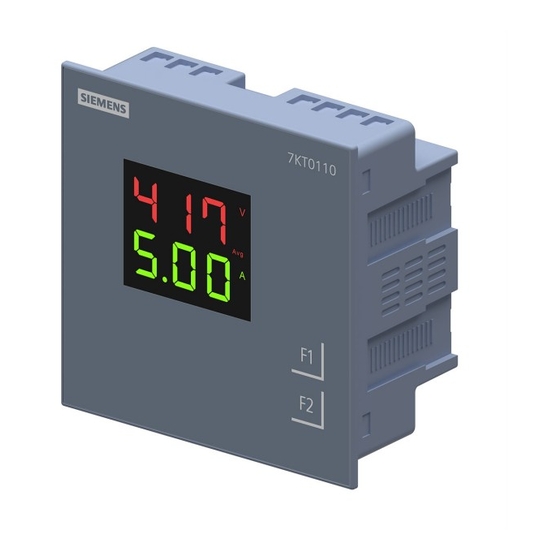
- Page 1 SMART 7KT0110 and 7KT0120 Manual MANUAL SMART 7KT Discrete Panel Meter 7KT0110 (VA meter) and 7KT0120 (VAF Meter) SMART 7KT power monitoring devices...
- Page 2 SMART 7KT0110 and 7KT0120 Manual Index SMART 7KT Introduction Discrete Panel Meter Safety precautions 7KT0110 (VA meter) and Technical specification 7KT0120 (VAF Meter) Installation Connection Configuration Maintenance Manual 09/2022 SME7KT01X001...
-
Page 3: Purpose Of This Document
SMART 7KT0110 and 7KT0120 Manual Introduction 1.1 Purpose of this document This present manual describes the SMART 7KT discrete panel meter. It is intended for the use of: • Planners • Plant operators • Commissioning engineers • Service and maintenance personnel 1.2 Required basic knowledge A general knowledge of the field of electrical engineering is required to understand this manual. -
Page 4: Safety Precautions
SMART 7KT0110 and 7KT0120 Manual Safety precautions DANGER Hazardous voltage will cause death or serious injury. Turn off and lock out all power supply before working on this device. NOTICE Installation and maintenance must be carried out by qualified personnel. This product has been designed for environment A. Use of this product in environment B may cause unwanted electromagnetic disturbances in which case the user may require to take adequate mitigation measures. Risk of damage: Please ensure the proper isolation of meter during the IR (Meggering) test. All safety related codifications, symbols and instructions that appear in this operating manual or on the equipment must be strictly followed to ensure the safety of the operating personnel as well as the instrument. If the equipment is not used in a manner specified by the manufacturer it might impair the protection provided by the equipment. -
Page 5: Technical Specification
SMART 7KT0110 and 7KT0120 Manual Technical specification 7KT0110 (VA meter) 7KT0120 (VAF meter) Power Monitoring Device Panel Power Monitoring Device Panel instrument for voltage and instrument for voltage, current current LED display Vaux: 95V to and frequency LED display Vaux: 240V AC x/1 or 5 A, Class 1 95V to 240V AC x/1 or 5 A, Class 1 Measurements measuring procedure • for voltage measurement True RMS True RMS • for current measurement True RMS True RMS type of measured value detection complete complete voltage curve Sinusoidal or distorted Sinusoidal or distorted measurable line frequency • initial value... - Page 6 SMART 7KT0110 and 7KT0120 Manual 7KT0110 (VA meter) 7KT0120 (VAF meter) Measuring inputs measurable supply voltage between L and N at AC maximum rated 240 V 240 V value measurable supply voltage between L and N at AC • minimum 11 V 11 V • maximum 300 V 300 V measurable supply voltage between the line conductors at AC 415 V 415 V maximum rated value measurable supply voltage between the line conductors at AC • minimum 19 V 19 V • maximum 519 V 519 V voltage measuring range extension with external voltage transformers up to 500kV up to 500kV...
-
Page 7: Installation
SMART 7KT0110 and 7KT0120 Manual Assembly Installation For installing the meter Prepare the panel cutout with proper dimensions as shown below. OUTLINE PANEL CUTOUT Dimensions (in mm) Dimensions (in mm) -
Page 8: Wiring Guidelines
SMART 7KT0110 and 7KT0120 Manual Installation Guidelines 1. This equipment, being built-in-type, normally becomes a part of main control panel and in such case the terminals do not remain accessible to the end user after installation and internal wiring. 2. Conductors must not come in contact with the internal circuitry of the equipment or else it may lead to a safety hazard that may in turn endanger life or cause electrical shock to the operator. 3. Circuit breaker or mains switch must be installed between power source and supply terminals to facilitate power ‘ON’ or ‘OFF’ function. However this switch or breaker must be installed in a convenient position normally accessible to the operator. 4. Before disconnecting the secondary of the external current transformer from the equipment, make sure that the current transformer is short circuited to avoid risk of electrical shock and injury. 5. The equipment shall not be installed in environmental conditions other than those mentioned in this manual. 6. The equipment does not have a built-in-type fuse. Installation of external fuse of 0.5 A, Class gG type for electrical circuitry is highly recommended. 7. Remove the scratch-guard from the meter display during commissioning of the panel. Wiring Guidelines 1. To prevent the risk of electric shock, power supply to the equipment must be kept OFF while doing the wiring arrangement. 2. Wiring shall be done strictly according to the terminal layout. Confirm that all connections are correct. 3. Use lugged terminals. 4. To reduce electromagnetic interference use of wires with adequate ratings and twists of the same in equal size shall be made with shortest connections. - Page 9 SMART 7KT0110 and 7KT0120 Manual Connection Typical Wiring Diagram - SMART 7KT0110 3 Phase - 4 Wire 2 Phase - 3 Wire 3 Ø - 4 Wire, 3 CT’s and 3 PT’s 2 Ø - 3 Wire, 2 CT’s and 2 PT’s 3 Phase - 4 Wire (commonly used) 3 Phase - 3 Wire 3 Ø - 4 Wire, 3 CT’S 3 Ø - 3 Wire, 2 CT’s and 2 PT’s...
- Page 10 SMART 7KT0110 and 7KT0120 Manual Typical Wiring Diagram - SMART 7KT0110 1 Phase - 2 Wire 1 Ø - 2 Wire, 1 CT’s Terminal Connections - SMART 7KT0110 Typical Wiring Diagram - SMART 7KT0120 3 Phase - 4 Wire 2 Phase - 3 Wire 3 Ø - 4 Wire, 3 CT’s and 3 PT’s 2 Ø - 3 Wire, 2 CT’s and 2 PT’s...
- Page 11 SMART 7KT0110 and 7KT0120 Manual Typical Wiring Diagram - SMART 7KT0120 (Continued) 3 Phase 4-Wire (commonly used) 3 Phase - 3 Wire 3 Ø - 4 Wire, 3 CT’S 3 Ø - 3 Wire, 2 CT’s and 2 PT’s 1 Phase - 2 Wire 1 Ø - 2 Wire, 1 CT Terminal Connections - SMART 7KT0120...
- Page 12 SMART 7KT0110 and 7KT0120 Manual Configuration There are 2 dedicated function keys labelled as F1 and F2. Use these 2 keys to read meter parameters. Use the soft-touch keys to read the parameters. The keys have multiple assignments. Function assignments and key labelling change according to the context of operator input. A short touch on the key triggers the function once. Touching the key for longer switches on the autorepeat function after approximately 1 s. The function of the key is triggered repeatedly while the key is touched. Autorepeat is useful, for example, for fast incrementing of values when parameterizing the device. Note: Image is representative SMART 7KT0110 Serial Number Description: Touch F1 for 10-15 secs to display 8 digit Serial number in 2 row & 2 pages. For Eg., 22010001 Page 1: Page 2: CONFIGURATION For the configuration setting mode: • Touch & Hold F1 + F2 key for 5 sec to enter and exit from configuration menu. • Touch F1 key to increment the configuration pages. • Use F2 key to edit the value and shift the cursor for next digit to edit. • Touch & Hold F2 key for 2 sec to save the parameter value. • Touch and hold F1 Key for 5 second to set CT/PT primary values in kilo from normal and vice versa.
- Page 13 SMART 7KT0110 and 7KT0120 Manual SMART 7KT0120 Serial Number Description: Touch F1 and hold the key for 10sec to display 8 digit Serial number in 3 row For Eg., 22010001 Page 1: CONFIGURATION For the configuration setting mode: • Touch & Hold F1 + F2 key for 5 sec to enter and exit from configuration menu. • Use F1 key to increment the configuration pages . • Touch F2 key to edit the value and shift the cursor for next digit to edit. • Use F2 key for 2 sec save the parameter value . • Press F1 Key for 5 second to set CT/PT primary values in Kilo from normal and vice versa. E.g.: If 1300 is to be set, first set the left most digit to 1, then hold the key for 2 sec to shift to kilo. The display will show 1.00k. The change the value after the decimal point to 3 to get the value of 1.3k. the hold the key for 2 sec to save the parameter. Factory default Config. Page. Function Range or Selection Setting Password 000-999...
- Page 14 SMART 7KT0110 and 7KT0120 Manual Reading of parameters- SMART 7KT0110 (VA meter) Online Page Description There are two dedicated keys labelled as F1 and F2. Use these 2 keys to read parameters. Touch these keys to read the parameters. Units of corresponding parameters on display will glow automatically. Key F1: To Increment Main Page. Key F2: To Increment subpages of respective Main Page Touch Key Screen Online Page Description For 3P4W Touch F1 1st main page Displays Line to Neutral voltage (L1-N) & 1st phase current. Touch F2 1st sub page Displays Line to Neutral voltage (L2-N) & 2nd phase current. Touch F2 2nd sub page Displays Line to Neutral voltage (L3-N) & 3rd phase current.
- Page 15 SMART 7KT0110 and 7KT0120 Manual Reading of parameters- SMART 7KT0120 (VAF meter) Online Page Description There are two dedicated keys labelled as F1 and F2. Use these 2 keys to read parameters. Touch these keys to read the parameters. Units of corresponding parameters on display will glow automatically. Key F1: To Increment Main Page. Key F2: To Increment subpages of respective Main Page Touch Key Screen Online Page Description For 3P4W Touch F1 1st main page Displays Line to Neutral voltage of three phase Touch F2 1st sub page Displays Line to Line voltage of three phase Touch F2 2nd sub page Displays Minimum Line to Neutral voltage of three phase Touch F2...
-
Page 16: Maintenance
Maintenance Guidelines • The equipment should be cleaned regularly to avoid blockage of ventilating parts. • Clean the equipment with a clean dry or damp cloth. Do not use any cleaning agent other than water. Disposal and recycling Dispose of or recycle the module in accordance with the applicable laws and regulations in your country. - Page 17 These instructions do not purport to cover all details or variations in Siemens. Any statements contained herein do not create new warranties equipment, or to provide for every possible contingency in connection or modify the existing warranty. with installation, operation, or maintenance. Should additional Trademarks - Unless otherwise noted, all names identified by ® are information be desired, please contact the local Siemens sales office. The registered trademarks of Siemens AG or Siemens Industry, Inc. The contents of this instruction manual shall not become part of or modify remaining trademarks in this publication may be trademarks whose use any prior or existing agreement, commitment, or relationship. The by third parties for their own purposes could violate the rights of the sales contract contains the entire obligation of Siemens. The warranty owner. contained in the contract between the parties is the sole warranty of Customer Care Toll free no. 1800 209 0987 Email: ics.india@siemens.com SACHIN ENTERPRISE Siemens Ltd. Product development is a continuous process. Consequently the data indicated in this Operating Instructions is subject to change without prior notice. For latest issue contact our sales offices.