Advertisement
Quick Links
GE
Security
8RP Board
Installation Sheet
Introduction
This installation sheet is designed to help experienced
technicians install the 8RP Board quickly. For more detailed
information, refer to the appropriate controller installation
manual.
The number of 8RP Boards supported by different host
software systems varies. Consult the manual that came
with your software for this information.
Features include:
•
Each 8RP Board is limited to only one type of reader
technology: F/2F or supervised F/2F.
•
External pull-up resistors are not required for the 8RP
Board.
•
No door DI (alarm) or exit DI points are available on the
8RP Board. Use of supervised readers is recommended
since these points are available on the reader.
•
If keypad readers are needed, use only GE supervised
F/2F keypad readers or Wiegand Interface Units (WIU-
2/WIU-4).
•
Each reader, reader-based DI (input) point, and reader-
based exit DI on the 8RP Board is addressed differently
depending on the host system you are using.
•
The 8RP Board provides one digital output (reader LED)
per reader port, 12 VDC, 100 mA maximum per output
point.
Verify contents
Caution:
While the 8RP has been designed to resist
electrostatic damage (ESD), it can be damaged by such
discharges. Always observe proper ESD precautions when
handling and storing the 8RP.
Inspect the package and contents for visible damage. If any
components are damaged or missing, do not use the unit;
contact the supplier immediately. If you need to return the
unit, you must ship it in the original box.
The package should include the following contents:
•
8RP Reader Board
•
8RP Board Installation Sheet (this document)
•
1N4004A protection diodes
•
MOV varistors
•
8-position, 45-degree connectors
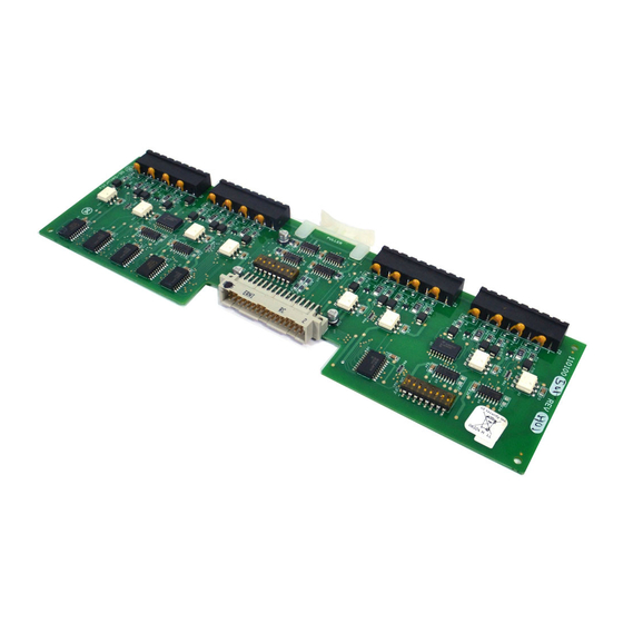
Figure 1: 8RP Board layout
1 of 6
P/N 460235001J • ISS 21MAR08
Advertisement

Related Manuals for GE 8RP Board


Summary of Contents for GE 8RP Board
- Page 1 MOV varistors Features include: • 8-position, 45-degree connectors • Each 8RP Board is limited to only one type of reader Figure 1: 8RP Board layout technology: F/2F or supervised F/2F. • External pull-up resistors are not required for the 8RP Board.
-
Page 2: Device Addressing
Setting the DIP switches Set the DIP switches as described in the tables below before installing and wiring the 8RP Board. Table 4: DIP switch settings for reader technology and format Reader technology and format SW 1-1... - Page 3 Reader port Signal name Typical wire color on the 8RP Board as shown in Figure 3, Figure 4, and Figure 5. Refer to Table 6 for connector pinouts. 1/3/5/7 +12 VDC Pairing of cables is very important. Refer to the...
- Page 4 Wiring the door strike Install a protection diode across the relay and the door strike. Use 1N4002, 1N4003, 1N4004 or One reader LED (door DO) is dedicated to each reader. equivalent diodes for DC door strikes and Metal Oxide The reader LED (door DO) is used for the reader LED or for Varistors (MOV) for AC door strikes.
- Page 5 Figure 4: Powering two 8RP Boards Figure 5: Wiring 8RP to WIU-4/Wiegand readers P/N 460235001J • ISS 21MAR08 5 of 6...
-
Page 6: Specifications
7 p.m. EST, Monday through Friday. Output One digital output (reader LED) per reader port, GE Security 12 VDC, 100 mA maximum per output point. United States: 1-888-GE SECURITY (1-888-437-3287) Cabling Multi-conductor, 20 AWG shielded pairs Asia: 852-2907-8108 Operating environment...