Table of Contents
Advertisement
Quick Links
Advertisement
Table of Contents

Related Manuals for Gigabyte GA-F2A58-DS3


Summary of Contents for Gigabyte GA-F2A58-DS3
- Page 1 GA-F2A58-DS3 User's Manual Rev. 3001 12ME-F258DS3-3001R...
- Page 2 The trademarks mentioned in this manual are legally registered to their respective owners. Disclaimer Information in this manual is protected by copyright laws and is the property of GIGABYTE. No part of this manual may be reproduced, copied, translated, transmitted, or published in any form or by any means without GIGABYTE's prior written permission.
-
Page 3: Table Of Contents
Table of Contents GA-F2A58-DS3 Motherboard Layout ................4 GA-F2A58-DS3 Motherboard Block Diagram ..............5 Chapter 1 Hardware Installation ..................6 Installation Precautions ..................6 ..................7 Installing the APU ..................... 9 Installing the Memory ..................9 Installing an Expansion Card ................. 10 ..........10 Back Panel Connectors .................. -
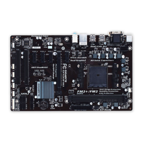
Page 4: Ga-F2A58-Ds3 Motherboard Layout
GA-F2A58-DS3 Motherboard Layout ATX_12V KB_MS CPU_FAN Socket FM2+ R_USB2 R_USB1 SYS_FAN1 USB_LAN SYS_FAN2 AUDIO PCIEX1_1 GA-F2A58-DS3 Realtek ® PCIEX16 GbE LAN PCIEX1_2 CODEC PCIEX1_3 AMD A58 B_BIOS M_BIOS PCIEX1_4 ® SATA2 Super I/O PCI1 PCI2 CLR_CMOS F_AUDIO F_USB3 F_USB2 F_USB1... -
Page 5: Ga-F2A58-Ds3 Motherboard Block Diagram
GA-F2A58-DS3 Motherboard Block Diagram 1 PCI Express x16 1 PCI Express x1 PCIe CLK AMD APU Dual Channel Memory DVI-D D-Sub PCI Express Bus 3 PCI Express x1 Dual BIOS RJ45 Realtek ® PCIe CLK 6 SATA 3Gb/s GbE LAN 14 USB 2.0/1.1... -
Page 6: Chapter 1 Hardware Installation
Chapter 1 Hardware Installation Installation Precautions The motherboard contains numerous delicate electronic circuits and components which can become manual and follow these procedures: Prior to installation, make sure the chassis is suitable for the motherboard. warranty sticker provided by your dealer. These stickers are required for warranty validation. Always remove the AC power by unplugging the power cord from the power outlet before installing or removing the motherboard or other hardware components. - Page 7 * The maximum 64 GB of system memory can be supported using 16 GB or above memory modules. GIGABYTE will update the memory support list on the of cial website when the memory modules are available on the market.
- Page 8 Internal 1 x 24-pin ATX main power connector Connectors 1 x 8-pin ATX 12V power connector 6 x SATA 3Gb/s connectors 1 x APU fan header 3 x system fan headers 1 x front panel header 1 x front panel audio header 1 x S/PDIF Out header 4 x USB 2.0/1.1 headers 1 x serial port header...
-
Page 9: Installing The Apu
Form Factor ATX Form Factor; 30.5cm x 19.0cm prior notice. * Please visit the Support & Downloads\Utility for the software listed in the "Unique Features" and "Bundled Software" columns. Installing the APU Read the following guidelines before you begin to install the APU: Make sure that the motherboard supports the APU. -
Page 10: Installing An Expansion Card
Due to APU limitations, read the following guidelines before installing the memory in Dual Channel mode. Dual Channel mode cannot be enabled if only one DDR3 memory module is installed. When enabling Dual Channel mode with two memory modules, it is recommended that memory of the same capacity, brand, speed, and chips be used for optimum performance. - Page 11 D-Sub Port The D-Sub port supports a 15-pin D-Sub connector and supports a maximum resolution of 1920x1200 D-Sub connection to this port. DVI-D Port Connect a monitor that supports DVI-D connection to this port. Please note that the actual resolutions supported are dependent on the monitor being used and support for 2560x1600 resolution requires both a monitor and cable that support Dual Link DVI.
-
Page 12: Internal Connectors
Internal Connectors ATX_12V F_USB1/2/3/4 SATA2 0/1/2/3/4/5 Read the following guidelines before connecting external devices: First make sure your devices are compliant with the connectors you wish to connect. Before installing the devices, be sure to turn off the devices and your computer. Unplug the power cord from the power outlet to prevent damage to the devices. - Page 13 With the use of the power connector, the power supply can supply enough stable power to all the components off and all devices are properly installed. The power connector possesses a foolproof design. Connect the power supply cable to the power connector in the correct orientation. The 12V power connector mainly supplies power to the APU.
- Page 14 The SATA connectors conform to SATA 3Gb/s standard and are compatible with SATA 1.5Gb/s standard. Each SATA connector supports a single SATA device. The AMD Chipset supports RAID 0, RAID 1, RAID 10, and SATA2 Pin No. are to be used, the total number of hard drives must be an even number. To enable hot-plugging for the SATA ports, refer to Chapter 2, "BIOS Setup,"...
- Page 15 your chassis front panel audio module to this header. Make sure the wire assignments of the module connector match the pin assignments of the motherboard header. Incorrect connection between the module connector and the motherboard header will make the device unable to work or even damage it. For HD Front Panel Audio: For AC'97 Front Panel Audio: Pin No.
- Page 16 The COM header can provide one serial port via an optional COM port cable. For purchasing the optional COM port cable, please contact the local dealer. Pin No. Pin No. NDCD- NDSR- NSIN NRTS- NSOUT NCTS- NDTR- NRI- No Pin Open: Normal Short: Clear CMOS Values Always turn off your computer before clearing the CMOS values.
-
Page 17: Chapter 2 Bios Setup
To access the BIOS Setup program, press the <Delete> key during the POST when the power is turned on. To upgrade the BIOS, use either the GIGABYTE Q-Flash or @BIOS utility. Q-Flash allows the user to quickly and easily upgrade or back up BIOS without entering the operating system. - Page 18 M.I.T. This section provides information on the BIOS version, CPU base clock, CPU frequency, memory frequency, Whether the system will work stably with the overclock/overvoltage settings you made is dependent on your overall and reduce the useful life of these components. This page is for advanced users only and we recommend you not to M.I.T.
- Page 19 Core Performance Boost Turbo Performance Boost Ratio Core Performance Boost Ratio AMD Cool&Quiet function Disabled Disables this function. cTDP function SVM Mode C6 Mode Allows you to determine whether to let the CPU enter C6 mode in system halt state. When enabled, the CPU core frequency will be reduced during system halt state to decrease power consumption.
- Page 20 Advanced Memory Settings The settings above are synchronous to those under the same items on the Advanced Frequency Settings menu. Memory Timing Mode Manual and Advanced Manual allows the Channel Interleaving, Rank Interleaving, and memory timing settings When using a non-XMP memory module or is set to Disabled, the value is set to , the value is displayed according to the SPD data on the XMP memory.
-
Page 21: System Information
CPU Temperature Warning Sets the warning threshold for CPU temperature. When temperature exceeds the threshold, BIOS will emit C/140 F, 70 C/158 F, 80 C/176 F, 90 C/194 CPU/System Fan Fail Warning Allows the system to emit warning sound if the CPU fan or system fan are not connected or fail. Check the CPU Fan Speed Control Normal Allows the fan to run at different speeds according to the CPU temperature. -
Page 22: Bios Features
System Language Selects the default language used by the BIOS. System Date value. System Time Sets the system time. The time format is hour, minute, and second. For example, 1 p.m. is 13:0:0. Use key to set the desired value. Access Level BIOS settings;... - Page 23 System A password is required for booting the system and for entering the BIOS Setup program. Allows you to determine whether to display the GIGABYTE Logo at system startup. Disabled skips the Fast Boot Enables or disables Fast Boot to shorten the OS boot process. Ultra Fast provides the fastest bootup VGA Support Allows you to select which type of operating system to boot.
- Page 24 Boot Mode Selection Allows you to select which type of operating system to boot. UEFI and Legacy Allows booting from operating systems that support legacy option ROM or UEFI Legacy Only Allows booting from operating systems that only support legacy Option ROM. UEFI Only Allows booting from operating systems that only support UEFI Option ROM.
-
Page 25: Peripherals
Peripherals HD Audio Azalia Device If you wish to install a 3rd party add-in audio card instead of using the onboard audio, set this item to Disabled. Legacy USB Support EHCI Hand-off Determines whether to enable EHCI Hand-off feature for an operating system without EHCI Hand-off Port 60/64 Emulation Enables or disables emulation of I/O ports 64h and 60h. - Page 26 Primary Video Device graphics. NB PCIe Slot Video Sets the PCI Express graphics card on the PCI Express slot controlled by the Integrated Graphics Enables or disables the onboard graphics function. Auto The BIOS will automatically enable or disable the onboard graphics depending on Disabled Disables the onboard graphics.
-
Page 27: Power Management
Power Management Resume by Alarm If enabled, set the date and time as following: Wake up hour/minute/second: Set the time at which the system will be powered on automatically. Note: When using this function, avoid inadequate shutdown from the operating system or removal of the AC power, or the settings may not be effective. -
Page 28: Save & Exit
Set the password when is set to Password. Press <Enter> on this item and set a password with up to 5 characters and then press <Enter> to accept. To turn on the system, enter the password and press <Enter>. Note: To cancel the password, press <Enter> on this item. When prompted for the password, press <Enter> again without entering the password to clear the password settings. -
Page 29: Chapter 3 Appendix
Boot Override Allows you to select a device to boot immediately. Press <Enter> on the device you select and select Yes Ensure is enabled under to RAID. - 29 -... - Page 30 This mode supports Windows 8 64-bit installation only. Steps: In BIOS Setup, go to and set Windows 8 Features to Windows 8 and CSM Support to Save the changes and exit BIOS Setup. Running the UEFI RAID Utility as shown in Figure 3. To run the UEFI RAID utility, enter the following commands. You can enter the commands at Shell or fsx: Checking Disk Information To see the hard drive information, enter the following commands and press <Enter>.
- Page 31 2. The selection bar will move to the Disks section on the right of the screen. Select the hard drives to be included in the RAID array. Use the up or down arrow key to select a hard drive and press <Insert>. The selected hard drive will be shown in green.
-
Page 32: Drivers Installation
You can click the Install All button and "Xpress Install" will install all the recommended drivers. Or click Install Single Items to manually select the drivers you wish to install. For more software information, please visit GIGABYTE's website. - 32 -... -
Page 33: Regulatory Statements
This document must not be copied without our written permission, and the contents there of must not be imparted Contravention will be prosecuted. We believe that the information contained herein was accurate in all respects at the time of printing. GIGABYTE cannot, however, assume any responsibility for errors or omissions in this text. as a commitment by GIGABYTE. - Page 34 This equipment has been tested and found to comply with the limits for a Class B digital device, pursuant to Part 15 of the FCC Rules. These limits are designed to provide reasonable protection against harmful interference in a residential installation. This equipment generates, uses, and can radiate radio frequency energy and, if not installed and used in accordance with the instructions, may cause harmful interference to radio communications.
- Page 35 - 35 -...
-
Page 36: Contact Us
Address: No.6, Bao Chiang Road, Hsin-Tien Dist., New Taipei City 231,Taiwan TEL: +886-2-8912-4000, FAX: +886-2-8912-4005 You may go to the GIGABYTE website, select your language in the language list on the top right corner of the website. GIGABYTE Global Service System question, please link to: http://ggts.gigabyte.com.tw...