Advertisement
Quick Links
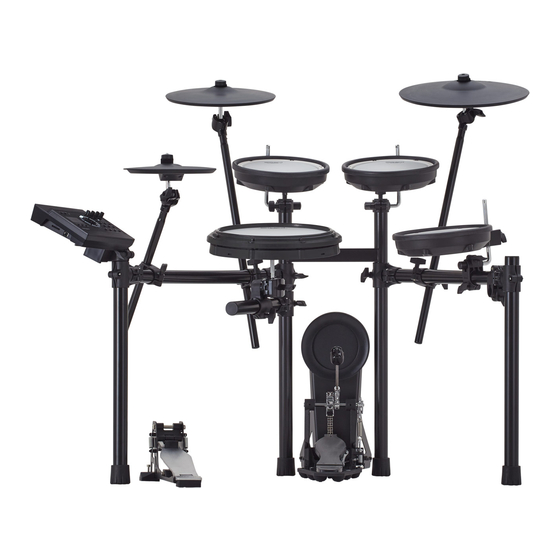
TD-17KV2
Check the included items
01
MDS-Compact
* For the items included with
the stand (MDS-Compact),
refer to the owner's manual
when checking that all
items are included.
· Hi-hat control pedal
(FD-9)
Assemble the stand
02
* The tip of the mount is sharp. Handle it with care.
* When setting up or storing the stand, be careful not to pinch the fingers you use to
handle the stand.
Assembly procedure
Assemble the stand (MDS-Compact) as type A (for hi-hat) following the procedure
described in the owner's manual.
Loosen this hand knob, and rotate the
mount holder (L) 90 degrees in the direction
of the arrow.
Cymbal mount
Cymbal mounts
Pad mounts
Pad mounts
If the stand wobbles, loosen
this hand knob and adjust
the height.
* For reasons of safety, do not spread the stand
wider than 1.2 meters (47 inches).
Connect the pads to TD
04
Connection procedure
1.
2.
Connect the cable to TD as shown in the
illustration.
Insert the connector all the way, then turn
the knobs to fasten it securely.
Knob
For a left-handed setup
The setup described in this guide is for right-handed players. To set up for a left-handed player,
reattach the components as follows.
¹ Exchange curved pipes (L) and (R), and straight pipes (L) and (R), left-for-right.
¹ Attach holder (C) and the snare pipe to the right side.
¹ Attach the mount holder (L) to the curved pipe (L).
¹ Exchange the pads and cymbals with their attachment mounts left-for-right.
¹ Exchange the TD with its sound module mount left-for-right.
After exchanging the curved pipes, attach
the holders so that the marks on the pipes
are visible through the gaps of the holders.
Remove the caps, remove holder (C) and the snare pipe, and
reattach them to the right side.
This completes assembly and connections.
Setup Guide
As soon as you open the package, check to see that all items are included. If anything is missing, please contact your dealer.
* This package does not include a kick pedal. Use with a commercially available kick pedal.
· Kick pad (KD-10)
· Cymbal pad for hi-hat
· V-Cymbal for crash (CY-12C-T)
· V-Cymbal for ride (CY-14R-T)
(CY-5)
03
Attach the hi-hat (CY-5)
"Roland" logo on the farther side
Tighten the cymbal nut enough to prevent the
pad from wobbling when you strike it. Use the
cymbal nut and felt washer that are included
with the stand.
If you're using this unit on a V-Drums mat, on a noise eater
(NE-10), or on carpet, extending the anchor bolts will secure
the unit in place, making it easier for you to perform.
When using on the V-Drums mat,
noise eater, or carpet
Adjusting the position of the cymbal
1.2 m
Adjust the height of the rod so that the highest
point of the cymbal is less than 1.2 meters.
* Fasten the cables so that they will not
obstruct your playing; use cable clips
and cable ties.
Labels indicating the pad to be connected
Make sure to wrap the cable ties
are attached to the cable. Connect the
around the pipes.
cable to the OUTPUT jack of each pad as
shown in the illustration.
* Insert the plug firmly,
making sure it's all the
way in.
(RD) (RDB)
CY-14R-T
(T3)
PDX-8
Mark
Curved pipe R
(including the pad mount)
Straight pipe R (short)
Parts of the TD-17KV
· V-Pad for snare (PDX-12)
· V-Pad for tom (PDX-8 x 3)
Attach the parts
Cymbal nut
Felt washer
Attach the TD
1.
Align the protrusions of the
sound module mount with the
rails of the TD, and slide it in until
you hear it click.
2.
Loosen the hand knob of the
mount holder, and insert the
sound module mount.
3.
Adjust the angle of the TD, and
then tighten the hand knob.
Place the hi-hat control pedal (FD-9)
* The tips of the anchor bolts are
sharp. Handle with care.
Anchor bolts
* When used on flooring, the
anchor bolts may damage the
floor.
When using on the floor
Attach the cymbal so that its center does not
extend toward the back beyond the pipes of
the stand (the pipes at the back of the stand).
1.2 m
As seen from the back
RDB
RD
T2
T1
T3
KIK
(CR1)
CY-12C-T
(T2)
(T1)
PDX-8
PDX-8
(HH)
CY-5
TD-17
(SNR)
PDX-12
(KIK)
KD-10
Curved pipe L
Straight pipe L (long)
(HHC)
FD-9
à When you've finished making connections, turn on the power as described in the TD-17/17-L Owner's Manual, and
verify that you can hear sound.
In order to use this device correctly, please carefully read "Using
the Unit Safely" and "Important Notes" (included in each owner's
manual) before use.
· Drum sound module (TD)
· Connection cable
(TD-17)
(special for TD)
Attach the crash cymbal (CY-12C-T) and ride cymbal (CY-14R-T)
"Roland" logo on the farther side
Tighten the cymbal nut enough to allow an appropriate
amount of sway. Use the cymbal nut and felt washer that
are included with the stand.
CY-12C-T
PDX-8
CY-5
TD-17
PDX-12
FD-9
Attach the kick pedal (KD-10)
Install the kick pedal securely.
OK
Not OK
Connect the AC adaptor and
05
speakers
CR1
Connect the AC adaptor, speakers, or headphones as described in the owner's
manual of the TD.
HH
* To prevent malfunction and equipment failure, always turn down the volume, and turn off all the
TD-17
units before making any connections.
SNR
HHC
Connect the cables as shown in the illustration.
As seen from the back
CR1
RD
RDB
T1
T2
HH
SNR
TD-17
T3
KIK
HHC
*5100079481-01*
© 2022 Roland Corporation
· Setup Guide (this document)
· Owner's manual set
· Drum key
· AC adaptor
Cymbal nut
Felt washer
CY-14R-T
PDX-8
PDX-8
KD-10
Adjust the location at which
the KD-10 is installed so that
it's at a comfortable position
for playing.
Attach the snare (PDX-12) and
toms ( PDX-8)
Tighten
Loosen
Rod
Tighten
Loosen
Rod
Advertisement

Related Manuals for Roland V-Drums TD-17KV2


Summary of Contents for Roland V-Drums TD-17KV2
- Page 1 Attach the crash cymbal (CY-12C-T) and ride cymbal (CY-14R-T) * When setting up or storing the stand, be careful not to pinch the fingers you use to handle the stand. “Roland” logo on the farther side Attach the hi-hat (CY-5) Assembly procedure...
- Page 2 Detailed explanation of each part à KD-10 (Kick) Attach the kick pedal. Step on the kick pedal and make sure that it’s properly attached When Using a Twin Pedal and in a stable position. Position the beater so that it strikes the Check to make sure that the base of the KD-10 and the kick pedal both make contact center of the head, then secure the kick Position the two beaters equally apart from the center of the pad as shown in...