Advertisement
Quick Links
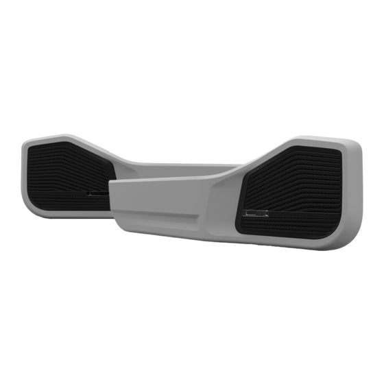
LC70 - 69P Installation Guide
Toyota Landcruiser 70 Series (VDJ) 09/2010 > Current
This owners manual will give you a clear understanding about the installation of this kit. To ensure correct installation, please read this manual carefully before starting the installation.
Advertisement

Related Manuals for Alpine LC70-69P


Summary of Contents for Alpine LC70-69P
- Page 1 LC70 - 69P Installation Guide Toyota Landcruiser 70 Series (VDJ) 09/2010 > Current This owners manual will give you a clear understanding about the installation of this kit. To ensure correct installation, please read this manual carefully before starting the installation.
-
Page 3: Tools & Hardware
Alpine Authroised Specialist Dealers. case of short-circuit. Alpine Electronics is not liable for any incorrect • Be sure to connect the specified leads according installation, fitment or modification inflicted on the to the diagram. - Page 4 Tools & Hardware Parts Rivnut Tool Electric Drill Front Exocasing - Left and Right. Rear Exocasing - Left and Right. Marker Multimeter Tough Grills - Left and Right Tweeter Housings - Left and Right Tweeter Chrome Rings (x2) LED Puddle lights - Left and Right Hammer and Center punch Powered cutting tools (Wood and Metal)
- Page 5 Parts Parts USB Port Cables (x4) Voltage Regulator M6 Rivnuts (x10) M6 Hex Bolts (x10) Voltage Regulator Bracket Voltage Regulator M3 Screws (x4) Exocasing Mounting screws (x74) Low profile Large Self tapping screw Mounting Templates Front and Rear Sandpaper (Not provided) Zip Ties x2 and Rubber Hole Plugs (x6) Masking Tape (Not provided)
- Page 6 Tear Down: Front Door Tear Down: Front Door To begin the installation process, all door cards will need to be removed. With the control panel loose. Take a precision flat head screw driver and push down on the locking tab of the wiring harness plug while simultaniously pulling to release. Using a trim removal tool and pry the front edge of the electric window panel up to Access screws behind the grab handle by removing the covers with a trim removal release it from the arm rest.
- Page 7 Tear Down: Front Door Tear Down: Front Door With the screws now in view, they an be removed with a PH2 Phillips screwdriver. Slide the handle mechanism towards the front of the vehcile and away from the door to release it. The final screw is holding the door handle in place.
- Page 8 Tear Down: Front Door Tear Down: Rear door Take the door card and manuveour it so you can pull the door handle through the door The tear-down process now moves onto the rear door cards. cards opening. The wiring harness will also need to be fed through the opening in the door card.
- Page 9 Tear Down: Rear door Tear Down: Rear door Using a precision flat head screw driver to push down the locking tab on the wiring Using a PH2 phillips head screw driver remove the arm rest screws. harness plug while simultaneously pulled the plug from the control panel. As before pry loose the screw covers with the armrest from the side to avoid damage.
- Page 10 Tear Down: Rear door Tear Down: Rear door With the screw removed slide the handle towards the front of the vehcile and then out Take the door card and manuveour it so you can pull the door handle through the door to free it from the door.
- Page 11 Tear Down: Dash Panel Tear Down: Dash Panel Take a trim removal tool and carefully pry it underneath the dash panel. There is a Hex Bolt below the panel. Remove using 8mm ring spanner as shown. There are several clipping points so firm pressure will need to be applied to release Replace using supplied hex screw.
- Page 12 Tear Down: Speaker Panel Preperation: Front Door Use a trim tool to remove the factory speaker cover. Turn over the Front door cards. Remove the bottom plastic push clips from the card. Place them aside for use later. Under the grill you will find the factory 3” speaker. Use a 10mm socket to remove the Now take the provided template and place it on the rear of the door card.
- Page 13 Preperation: Front Door Preperation: Front Door With the template confidently in place. Use masking tape to hold it in place. You will With holes marked. Pre drill your door card. 3mm and 6mm drill bits are required for need to reuse this template so be sparring when taping it down. this step.
- Page 14 Preperation: Front Door Preperation: Front Door The template can now be carefully removed. Next take your drill with a 9mm drill bit The next step requires a soft test mounting of the Front Door pod. Lay the door card and drill out the indicated 3 back holes previously used to mount the map pocket. down on the pod and line up your pre drill holes.
- Page 15 Preperation: Front Door Preperation: Front Door Please test mount assembly to the door by lining up the push clips with the doors Then take a marker and place it down the larger boss holes in the speaker area to mounting holes. mark on the sheet metal where the rivnuts will need to be installed.
- Page 16 Preperation: Front Door Preperation: Front Door Use your prefered sheet metal cutting tools, such as a air hacksaw or similiar to cut Use a drill and 3mm bit to create a pilot hole. Then use the 9mm drill bit to create the the marked speaker clearance hole in the door.
- Page 17 Preperation: Front Door Preperation: Rear Door Use a Rivnut tool to mount the provided M6 Rivnuts into the 9mm holes in the door Take the provided template and place it on the rear of the door card. Using the push sheet metal.
- Page 18 Preperation: Rear Door Preperation: Rear Door Take the hole punch and mark out the pre cut holes of the template. These will help With the template still in place. Use a marker to draw an oval on the back of the door with precision drilling.
- Page 19 Preperation: Rear Door Preperation: Rear Door The next step requires a soft test mounting of the Front Door pod. Lay the door card Place the test mounted assembly to your door by lining up the push clips with the down on the pod and line up your pre drill holes. We recommend using only a portion doors mounting holes.
- Page 20 Preperation: Rear Door Preperation: Rear Door Take the marker and place it down the larger boss holes in the speaker area to mark Use your prefered sheet metal cutting tools, such as a air hacksaw or similiar to cut on the sheet metal where the rivnuts will need to be installed. the marked speaker clearance hole in the door.
- Page 21 Preperation: Rear Door Preperation: Rear Door Use a drill and 3mm bit to creat a pilot hole. Then use the 9mm drill bit to create the Use a Rivnut tool to mount the provided M6 Rivnuts into the 9mm holes in the door hole for the rivnut itselt.
- Page 22 Clip the LED into place by applying firm pressure to the NON clip side until it pushes Take the Component Speaker from your chosen Alpine Speaker kit. Turn the into the pod. Then push the other side of the LED into place. You should see the light exocasing over and place the speaker into the pod using the x4 bosses to locate it.
- Page 23 Assembly: Front Exocasing Assembly: Front Exocasing With the speaker seated use your drill and PZ2 bit to carefully drive the supplied With your door cards and Front exocasing complete. Secure exocasing to card using Exocasing screws in. supplied mounting screws. Take the provided rubber plugs and place them into the 9mm holes you drill earlier.
- Page 24 Before remounting the rear exocasing. Secure the USB wires on the indicated boss To assemble the tweeter panels. Start by taking your choice of Alpine Tweeter and with a zip tie. Feed the excess wiring out the speaker hole of the card.
- Page 25 Assembly: Tweeter Panel Assembly: Voltage Regulator PASSENGER SIDE DRIVERS SIDE Mount the provided Voltage regulator to the regulator bracket using the provided With the Tweeter loose from the retail mounting assembly. Feed the wires through the machine screws. hole of the provided Tweeter Panel. Snap the Tweeter into place by seating the bottom edge first and levering the top edge down.
- Page 26 Wiring: Voltage Regulator Wiring: LED Lights Speakers Finally find a accesory power source and suitable ground to connect to the Input of Enough wire length to converge on each corrosponding wire purpose will be required. the regulator. ie. USB’s to Regulator, LED’s to constant power and door trigger and Speakers to headunit/amplifier.
- Page 27 Installation: Front Exocasing Installation: Front Exocasing With the +/- Speaker wire,+/- USB wire and +/- LED wire routed into the front doors With the door card/assembly mounted, secure it with the M6 bolts supplied with the of the vehicle. Terminate them into crimp connectors or solder them to the loose wires 10mm socket and wrench.
- Page 28 Installation: Front Exocasing Installation: Rear Exocasing Reassemble the window control panel and remount the door handle. The Front Once the wiring is complete. Mount the assembly to the door. Ensure all plastic push Exocasing assembly is now installed. clips are mounted back onto the door card. With the +/- Speaker wire and +/- USB wire routed into the rear doors of the vehicle.
- Page 29 Installation: Rear Exocasing Installation: Tweeter Panel Attach the Tough Grill. Do this by placing the back edge of the grill into the Pod on a Feed the +/- Speaker wire through the hole in the dash down towards the kick panel slight angle.
- Page 30 Installation: Tweeter Panel INSTALL COMPLETE The Alpine Tweeter is now mounted into the dash. Congatulations, the installation is now complete. Test and validate system to ensure proper functionality and fitment. ie; Power to each usb port. Sound from each speaker and proper acitivation of the LED puddle lights.
- Page 31 Notes Notes...