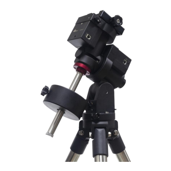
iOptron GEM28 Adjustment
Worm play
Hide thumbs
Also See for GEM28:
- Instruction manual (49 pages) ,
- Quick start manual (6 pages) ,
- Manual (6 pages)
Advertisement
Quick Links
Tool needed: a set of metric Allen wrench and a
small flat top screw driver, a pair of nose pliers or
tweezers.
GEM28 Ring Gear Cover Removal: RA
The design of GEM28 will need to remove the DEC
unit from the mount in order to expose the RA ring
gear compartment.
1. The DEC unit is connected to the RA axle via 4
socket screws. Two is on side the DC unit. One
is on bottom of the DEC unit. The fourth one is
inside the mount. Remove front polar scope
cover and look into the mount, you should see it.
2. Remove red CW shaft mounting adapter from
the bottom. The bottom screw now is easy to
access.
For iOptron Internal Use Only
GEM28 Worm Play Identification and Adjustment
3. To access the top screw, you may use a long
arm ball head wrench through the RA axis
opening to release it.
4. Pull the DEC unit off from the RA axle. Remove
three screws and take off the RA ring gear
cover.
1
Advertisement

Related Manuals for iOptron GEM28


Summary of Contents for iOptron GEM28
- Page 1 GEM28 Ring Gear Cover Removal: RA The design of GEM28 will need to remove the DEC unit from the mount in order to expose the RA ring gear compartment.
- Page 2 For iOptron Internal Use Only 7. Carefully unplug the motor cable from the DEC control board. 8. Unscrew the screw post and two screws that hold the plastic base cover in place. 5. If Step 3 does not work, we need to remove the DEC motor and control board to access the 9.
- Page 3 For iOptron Internal Use Only GEM28 Ring Gear Cover Removal: DEC 1. Use a 3.5mm hex wrench to remove 4 socket screws on dovetail saddle. Pull the dovetail saddle off the mount. (1) If the whole worm assembly moves up and springs back down, this is normal for a 2.
- Page 4 For iOptron Internal Use Only 7. Release hinge bearing end cap locking screw half turn. 4. Release two screws and remove the motor 8. Turn the brass end cap clockwise all the way in using a pair of strong tweezers or a screw driver.
- Page 5 For iOptron Internal Use Only 10. Thread the belt over motor pulley and attached the motor to the worm assembly. Tighten the screws slightly. Locking Pin 15. SLOWLY Pull the gear switch knob outwards. Put your palm underneath to collect the little spring and the ball bearing.
- Page 6 For iOptron Internal Use Only 18. Tap the bearing out of the housing if needed. The following is a set of a bearing, a washer and a hinge pin. Spring underneath the ball bearing 16. Release two set screws on mount assembly:...
- Page 7 For iOptron Internal Use Only 24. Wrap the belt over the worm pulley and insert the worm assembly back into the ring gear compartment. You may rotate the mount head 90 degree so the worm pulley and open-ended hinge pin bearing house is on top.
- Page 8 For iOptron Internal Use Only Ball bearing goes in this slot 30. Insert the spring into the gear switch hole. Put 27. Turn the brass end cap clockwise all the way in the ball bearing on top of it. Insert gear switch...
- Page 9 For iOptron Internal Use Only 32. Check the play with worm/ring gear engaged while rotating the ring gear. 33. Follow steps 10-12 to put the motor, control board and cover back.