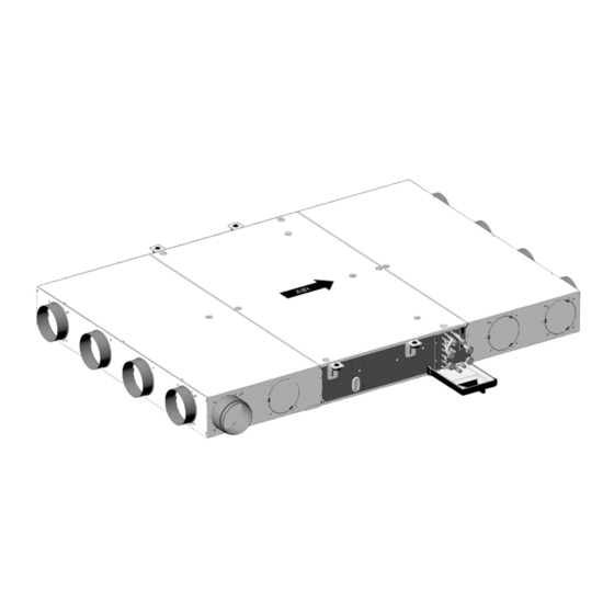
Carrier Idrofan 42EP Installation, Operation And Maintenance Instructions
Hydronic extra slim ducted fan coil units
Hide thumbs
Also See for Idrofan 42EP:
Summary of Contents for Carrier Idrofan 42EP
- Page 1 INSTALLATION, OPERATION AND M A I N T E N A N C E I N S T R U C T I O N S Hydronic Extra Slim Ducted Fan Coil Units 42EP Original document...
-
Page 2: Table Of Contents
ENGLISH CONTENTS 1 - PRECAUTIONS ............................... 11 1.1 - Operating limits ............................11 1.2 - Clearances required ............................ 11 1.3 - Receiving a shipment - installation methods ....................11 1.4 - Supply voltage .............................12 2 - SAFETY CONSIDERATIONS ..........................13 2.1 - General................................13 2.2 - Protection against electrocution ........................13 2.3 - General installation conditions ........................13 2.4 - Caution for the control of the unit ........................14... - Page 3 Floor unit Ceiling unit UNIT SIZE 42EP-SIZE 0 42EP-SIZE 1 1114 42EP-SIZE 2 1314 Ceiling unit Floor unit UNIT SIZE 42EP-SIZE 0 42EP-SIZE 1 1114 42EP-SIZE 2 1314...
- Page 4 Floor unit Ceiling unit UNIT SIZE 42EP-SIZE 0 42EP-SIZE 1 1114 42EP-SIZE 2 1314 Ceiling unit Floor unit UNIT SIZE 42EP-SIZE 0 42EP-SIZE 1 1114 42EP-SIZE 2 1314...
- Page 5 IMPROPER DAISY CHAIN CORRECT DAISY CHAIN Fmain UNIT 1 UNIT 1 Derivation box 1 UNIT 2 UNIT 2 Derivation box 2 UNIT 3 UNIT 3 Derivation box 3 Funit = sized as per IOM prescription accordingly with type of unit model Fmain= responsibility of the installer to ensure adequate short circuit protection of installation Ceiling unit...
- Page 6 Floor unit 10.2 10 a 10 b 11 a...
- Page 7 Ceiling unit Floor unit 12.2 12.1 Ceiling unit Floor unit...
- Page 9 Voir DETAIL A SEE DETAIL DETAIL A ECHELLE 3 : 10...
- Page 10 ENGLISH Figure titles and legends: 15 Meaning of wires - Proportional valve actuator (not applicable for valves with balancing functions) Base unit clearance - Clearances needs [mm] Black wire (230 V valve actuator), Units with rectangular flanges - Clearances needs [mm] actuator rod rising Units with compact plenum - Clearances needs [mm] Green wire (24 V valve actuator), Units with large plenums - Clearances needs [mm] actuator rod rising...
-
Page 11: Precautions
NOTE : All information's about dimensions and ethylene / propylene glycol rate < 40% Water circuit Water side pressure < 15,5 bar (1550 kPa) weights are available in the PSD documentation on Carrier Web portal Ambient T < 40°C temperature 1.3 - Receiving a shipment -... -
Page 12: Supply Voltage
Max : 253 V 60 or 50 Hz -1ph NOTE: All performances data certified by Eurovent are based on 50Hz application. Carrier doesn’t ensure the same performances when the unit operates at 60Hz; the RPM and power input of the fan-motor are usually higher. -
Page 13: Safety Considerations
They also comply with the low-voltage directive. buses must be carried out in accordance with the latest rules and regulations by professional If the product is supplied without a Carrier control installers. device, verification of EMC conformity is the - The power supply cable must be doubly insulated responsibility of the installer. -
Page 14: Caution For The Control Of The Unit
• Use the screened cable type recommended by Carrier and make sure all cables are connected to the controllers and power modules. 2.4 - Caution for the control of the unit IMPORTANT: It is not permitted to connect several... -
Page 15: Installation Of The Unit
Ensure that a gasket (not supplied by Carrier) is installed The method of fixing the threaded hangers (not between the screw connector and the stop valve. supplied by Carrier) depends on the ceiling/floor ... -
Page 16: Components And Maintenance
Floor units - Disconnect the flexible condensate drain pipe held - Remove the filter access door in case of units with in place by a collar (the collar is not supplied by inlet plenums. Carrier). - Remove the filter. - Remove the top panel. - Remove the bottom panel (ceiling unit) / top panel - Remove the coil (floor unit). -
Page 17: Spigots Duct Connection
The unit can be equipped with a variable fresh air flow controller from 0 to 55 l/s (0 to 200 m3/h). 4.6 - Rectangular flanges duct This is connected to the numeric Carrier controller and connection can regulate the fresh air intake in using a fixed rate set When connecting rectangular flanges to the inlet and by the installer that can be reconfigured as required. the outlet make sure that the duct is pushed closely the NOTE: With the variable fresh air flow controller the unit. -
Page 18: Flexible Pipe Option
- Disconnect the power supply to the unit before carrying out any work on a unit. - Disconnect the actuator power supply cable. • 230 V type actuator used with the Carrier numeric controller: Disconnect the actuator power supply cable fitted with a quick connector. • 230 V actuator used with an electronic thermostat: Remove the plastic protection cover held in place with two screws. -
Page 19: Optional Water Sensor
NOTE: In case of unit with an electrical box (for Carrier Thermostats), a “switch” is provided as an option instead of the water sensor. 4.12 - Optional condensate pump Check the sealing of the hydraulic connection of the condensate pump and condensate recovery. - Page 20 Order No.: EN7573046-00, 12.2019. Supersedes order No.: New. Manufacturer reserves the right to change any product specifications without notice. Printed in the European Union.


