Advertisement
Quick Links
[ 1 ] GENERAL . . . . . . . . . . . . . . . . . . . . . . . . . . . . . . . . . . . . . . . . 1 - 1
[ 2 ] SPECIFICATIONS . . . . . . . . . . . . . . . . . . . . . . . . . . . . . . . . . . 2 - 1
[ 3 ] CONSUMABLE PARTS . . . . . . . . . . . . . . . . . . . . . . . . . . . . . . 3 - 1
[ 4 ] EXTERNAL VIEWS AND INTERNAL STRUCTURES . . . . . . . 4 - 1
[ 5 ] UNPACKING AND INSTALLATION. . . . . . . . . . . . . . . . . . . . . . 5 - 1
[ 6 ] COPY PROCESS . . . . . . . . . . . . . . . . . . . . . . . . . . . . . . . . . . . 6 - 1
[ 7 ] OPERATIONAL DESCRIPTIONS. . . . . . . . . . . . . . . . . . . . . . . 7 - 1
[ 8 ] DISASSEMBLY AND ASSEMBLY . . . . . . . . . . . . . . . . . . . . . . 8 - 1
[ 9 ] ADJUSTMENTS . . . . . . . . . . . . . . . . . . . . . . . . . . . . . . . . . . . . 9 - 1
[10] SIMULATION,TROUBLE CODES . . . . . . . . . . . . . . . . . . . . . 10 - 1
[11] USER PROGRAMS . . . . . . . . . . . . . . . . . . . . . . . . . . . . . . . . 11 - 1
[12] ELECTRICAL SECTION . . . . . . . . . . . . . . . . . . . . . . . . . . . . 12 - 1
[13] CIRCUIT DIAGRAM . . . . . . . . . . . . . . . . . . . . . . . . . . . . . . . . 13 - 1
Parts marked with "
" are important for maintaining the safety of the machine.
Be sure to replace these parts with specified ones for maintaining the safety and performance of the machine.
(AL-1551)
CONTENTS
SHARP CORPORATION
CODE : 00ZAL1551/A2E
DIGITAL COPIER
AL-1043
AL-1252
AL-1452
AL-1551
MODEL
This document has been published to be used for
after sales service only.
The contents are subject to change without notice.
Advertisement

Related Manuals for Sharp AL-1043


Summary of Contents for Sharp AL-1043
- Page 1 CODE : 00ZAL1551/A2E DIGITAL COPIER AL-1043 AL-1252 AL-1452 AL-1551 (AL-1551) MODEL CONTENTS [ 1 ] GENERAL ........1 - 1 [ 2 ] SPECIFICATIONS .
- Page 2 CAUTION This product is a class 1 laser product that complies with 21CFR 1040.10 and 1040.11 of the CDRH standard and IEC825. This means that this machine does not produce hazardous laser radiation. The use of controls, adjustments or performance of procedures other than those specified herein may result in hazardous radiation exposure.
- Page 3 At the production line, the output power Caution of the scanner unit is adjusted to 0.57 This product contains a low power laser MILLI-WATT PLUS 20 PCTS and is device. To ensure continued safety do not maintained constant by the operation of remove any cover or attempt to gain access the Automatic Power Control (APC).
- Page 4 CONTENTS GENERAL DISASSEMBLY AND ASSEMBLY 1. Major functions........1-1 1.
- Page 5 1. Major functions Configurations Item SB/MB 2 Tray R-SPF GDI with PCL with SOPM Duplex without Model AL-1043 10CPM AL-1252 12CPM AL-1452 14CPM AL-1551 15CPM Descriptions of items CPM: Copy speed (Copies Per Minute) SB/MB: SB = Manual feed single bypass, MB = Manual feed multi bypass 2 tray: Second cassette unit.
- Page 6 AL-1551 54.3lbs.(24.6Kg) 2. Operation specifications Section, item Details Paper feed Paper feed AL-1043 / 1252 1 tray (250 sheet) + single bypass section system AL-1452 2 tray (500 sheet) + single bypass AL-1551 2 tray (500 sheet) + multi bypass (50 sheet)
- Page 7 Electrical section Power source Voltage 100V, 110V, 120/127V, 230V, 240V Frequency Common use for 50 and 60Hz Power consumption Max. 1000W Average AL-1043 260Wh/H *1) (during copying) AL-1252 280Wh/H *1) AL-1452 280Wh/H *1) AL-1551 310Wh/H *1) Average (stand-by) 70Wh/H *1)
- Page 8 3. Copy performance Section, item Details AL-1043 AL-1252 AL-1452 AL-1551 Copy magnification Fixed 3 Reduction + 2 Enlargement magnification (AB system : 50, 70, 81, 100, 141, 200%) ratios (Inch system : 50, 64, 78, 129, 100, 200%) Zooming 50 - 200%...
- Page 9 4. Printer specifications Resolution 600 or 300 can be selected. Page description language SHARP GDI Page onentation Portrait or Landscape First print time Approx. 9.6 seconds* Print speed(multiple pages) Max.12 pages per minute(letter or A4) Interface port Bi-directional parallel interface(IEEE 1284 compliant) First print time may differ depending on operating conditions, such as power-supply voltage and room temperature.
- Page 10 [3] CONSUMABLE PARTS 1. Supply system table Common to all destinations Name Content Life Product name Package Develop cartridge (Black) x 1 Toner/developer cartridge x 1 AL-100TD (Except Europe) (Toner: Net weight 220g)(Developer: Net weight 190g) (5% document) Develop cartridge (Black) x 1 Toner/developer cartridge x 1 AL-110TD (Except Europe)
- Page 11 3. Production control number(lot No.) identification <Developing cartridge> Production month Production day Destination code (Dealer, distributor, OEM, etc.) Production place (SOCC: Fixed to B.) End digit of year Version No. Production control label attachment position Destination Division EX Destination A same pack B same pack Option Destination <Drum cartridge>...
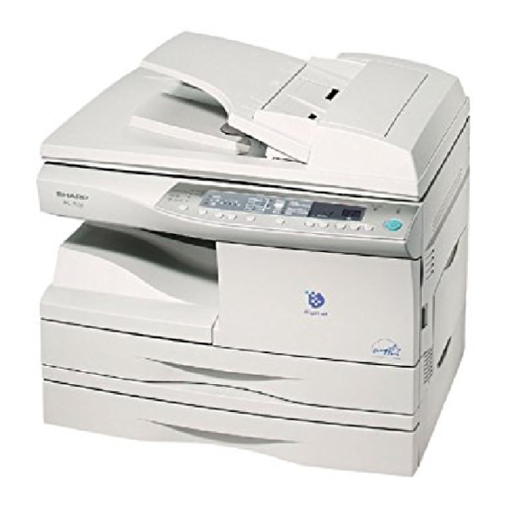
- Page 12 [4] EXTERNAL VIEWS AND INTERNAL STRUCTURES 1. Appearance Original cover RSPF Original cover Side cover Bypass tray Bypass tray guides Side cover open button Front cover Paper tray Operation panel Original table Handle GDI printer interface Paper output tray Paper output tray extension Handle Power switch Power cord socket...
- Page 13 3. Operation panel (AL-1551) Duplex Mode select key and indicator Exposure mode selector key and indicators (RSPF only) Use to sequentially select the exposure modes: AUTO, MANUAL or PHOTO. Selected mode is shown by a lit indicator. Light and dark keys and exposure indicators Alarm indicators Use to adjust the MANUAL or PHOTO exposure level.
- Page 14 4. Motors and solenoids Part name Control signal Function,operation Main motor Drives the copier. Mirror motor MRMT Drives the optical mirror base (scanner unit). Toner motor Supplies toner. Cooling fan motor Cools the optical section. Resist roller solenoid Resist roller rotation control solenoid Paper feed solenoid CPFS1 Cassette Paper feed solenoid 1...
- Page 15 5. Sensors and switches Name Signal Type Function Output Mirror home position sensor MHPS Transmission sensor Mirror (scanner unit) home position "H" at home position detection POD sensor Transmission sensor Paper exit detection "H" at paper pass PPD2 sensor PPD2 Transmission sensor Paper transport detection 2 "L"...
- Page 16 6. PWB unit Name Function Exposure lamp invertor PWB Exposure lamp (Xenon lamp) control Main PWB (MCU) Copier control Operation PWB Operation input/display Power PWB AC power input, DC voltage control, High voltage control CCD sensor PWB For image scanning LSU motor PWB For polygon motor drive TCS PWB...
- Page 17 7. Cross sectional view Part name Function and operation Scanner unit Illuminates the original with the copy lamp and passes the reflected light to the lens unit(CCD). Exposure lamp Exposure lamp (Xenon lamp) Illuminates original Lens unit Scans the original image with the lens and the CCD. LSU (Laser unit) Converts the original image signal into laser beams and writes onto the drum.
- Page 18 [5] UNPACKING AND INSTALLATION 2. Cautions on handling 1. Copier installation Be careful in handling the copier as follows to maintain the performance of this copier. Improper installation may damage the copier. Please note the following during initial installation and whenever the copier is moved. Do not drop the copier, subject it to shock or strike it against any object.
- Page 19 3. Checking packed components and 6. Installing the TD cartridge accessories The TD cartridge replacement required ( ) indicator will light up when toner is needed. If copying is continued while the indicator is lit, Open the carton and check if the following components and accessories copies will gradually become lighter until the copier stops and the are included.
- Page 20 4) Remove the TD cartridge from the bag. Remove the protective paper. 7. Loading copy paper Hold the cartridge on both sides and shake it horizontally four or five Note: This copier is equipped with two paper trays. Load copy paper into times.
- Page 21 8. Power to copier A. Windows 95/Windows NT 4.0 1) Load paper into the paper tray of the printer. 1) Ensure that the power switch of the copier is in the OFF position. 2) Turn on the printer. Insert the attached power cord into the power cord socket at the rear 3) Turn on your computer and start Windows.
- Page 22 OK button.. 6) Follow the on-screen instructions. 7) Windows driver file search will find the device “SHARP AL-1000 Series”. Click the Next button and follow the on-screen instructions. AL-1551 UNPACKING AND INSTALLATION 5-5...
- Page 23 E. AL-1000 Series printer driver group 10.Parallel interface When the printer driver is installed, the SHARP AL-1000 Series printer This printer uses a bi-directional parallel interface. Use the sup-plied driver group will be created. This group allows the following functions to interface cable.
- Page 24 [6] COPY PROCESS An OPC drum is used for the photoconductor. (Structure of the OPC drum layers) OPC layer (20microns thick) Pigment layer (0.2 to 0.3 microns thick) Aluminium drum 1. Functional diagram Main charger Laser beam Cleaning blade MG roller Drum Transfer unit Resist roller...
- Page 25 2. Outline of print process Step-2: Exposure (laser beam, lens) A Laser beam is generated from the semiconductor laser and controlled This printer is a non-impact printer that uses a semiconductor laser and by the print pattern signal. The laser writes onto the OPC drum surface electrostatic print process.
- Page 26 Step-3: Developing (DC bias) Step-4: Transfer A bias potential is applied to the MG roller in the two component The visible image on the drum surface is transferred onto the print paper magnetic brush developing method, and the toner is charged negative by applying a positive charge from the transfer corona to the backside of through friction with the carrier.
- Page 27 Step-7: Optical discharge (Semiconductor laser) Start Before the drum rotation is stopped, the semiconductor laser is radiated 1) Because the grid potential is at a low level, the drum potential is at onto the drum to reduce the electrical resistance in the OPC layer and about -400V.
- Page 28 [7] OPERATIONAL DESCRIPTIONS 1. Outline of operation The outline of operation is described referring to the basic configuration. (Basic configuration) Scanner section Operation section MCU (Main control/image process section) PCL control PCL I / F LSU (Laser unit) Laser diode, Polygon mirror lens Laser beam Paper exit Fusing section...
- Page 29 2. Scanner section B. Basic structure of scanner section A. How to scan documents (11) The scanner has sensors that are arranged in a line. These sensors scan a certain area of a document at a time and deliver outputs sequentially.
- Page 30 3. Laser unit B. Laser beam path The image data sent from the MCU (image process circuit) is sent to the LSU (laser unit), where it is converted into laser beams. A. Basic structure The LSU unit is the writing section of the digital optical system. The semiconductor laser is used as the light source, and images are formed on the OPC drum by the polygon mirror and fθ...
- Page 31 A. General description (3) Thermal control 1) The heater lamp, thermistor, main PWB, DC power supply PWB, and General block diagram (cross section) triac within the power supply unit are used to control the temperature Thermal fuse Separator pawl in the fuser unit. To prevent against abnormally high temperature in the fuser unit, a PPD2 thermal breaker and thermal fuse are used for safety purposes.
- Page 32 5. Paper feed section and paper transport 2) When the COPY button is pressed, the main drive motor starts rotating to drive each drive gear. section The pick-up drive gear also is driven at that time. Since, however, the paper feed latch is in contact with the projection of the clutch sleeve, A.
- Page 33 5) At this time, the paper is fed passed the paper entry detection switch (2) Manual multi paper feed operation (PPD1), and detected by it. After about 0.15 sec from detection of 1) Before paper feed operation, the manual paper feed solenoid paper by PPD1, the tray paper feed solenoid (PFS) turns on so that (MPFS) is turned OFF as shown in the figure below.
- Page 34 3) When pawl C of the manual paper feed clutch sleeve is engaged with 4) The lead edge of the transported paper is pressed on the resist roller the manual feed latch, the manual feed stopper falls and the manual by the transport roller.
- Page 35 6. Process unit new drum detection 2) When the detection gear 38T turns one rotation, there is no gear any more and it stops. mechanism The latch section of the 38T gear is latched and fixed with the projection of the process cover. 1) When the power is turned on, the detection gear 38T is rotated in the arrow direction by the detection gear 20T to push the microswitch (process detection switch) installed to the machine sensor cover,...
- Page 36 C. Operational descriptions 8. D-D (Duplex to Duplex) mode paper/ document transport (Duplex model) Time chart (Tray feed) Document set A. Initial state SPID ON Document set sensor Set duplex documents on the document tray. Set paper on the cassette. (In the duplex mode, the manual feed tray Document feed unit lamp ON cannot be selected.) Copy start...
- Page 37 C. Back copy Switchback operation is made after back copying in order to discharge Document transport: documents according to the setting. By switchback operation, the document is sent through the PS roller to Set document Documents after discharge, the exposure section, where the back of the document is exposed. with empty feed without empty feed •...
- Page 38 [8] DISASSEMBLY AND ASSEMBLY 2) Push up the lock pawls (2 positions) of the side cover, and remove the transfer charger. Before disassembly, be sure to disconnect the power cord for safety. Lock pawl rear The disassembly and assembly procedures are described for the following sections: 1.
- Page 39 2) Set the charger cleaner to the transfer unit, and move it reciprocally a 2. Operation panel section few times in the direction of the arrow shown in the figure below. A. List Part name Ref. Operation panel unit Operation PWB B.
- Page 40 3. Optical section 2) Remove the screws (2pcs.), and remove the copy lamp unit from the mirror base drive wire. A. List Part name Ref. Copy lamp unit Copy lamp Lens unit B. Disassembly procedure 1) Remove the parts as shown below. Hook 3) Pull the copy lamp unit toward you to remove the harness.
- Page 41 4) Remove the screw (4 pc) and remove the cover. 4. Fusing section 5) Remove the screws (2 pcs.), the harness, and the optical unit. A. List Part name Ref. Thermistor PPD2 sensor Heater lamp Pressure roller Heat roller B. Disassembly procedure 1) Remove the connectors (3 pcs.) of the rear cabinet.
- Page 42 4) Remove the screw and remove the U-turn guide. 7) Remove the plate spring on the right and remove the heater lamp. Pressure roller section disassembly Hearter lamp 5) Remove the three screws, remove the fusing cover lower on the right side, and open the heat roller section.
- Page 43 10) Remove the pressure release levers on the right and the left sides. 6) Remove the C-ring and the fusing bearing, and remove the heat roller. Heat roller 11) Remove the pressure roller, the pressure bearing, and the spring. 7) Remove the parts from the heat roller. Note: Apply grease to the sections specified with*.
- Page 44 5. Tray paper feed/transport section 3) Remove two screws and remove the toner motor. A. List Part name Ref. PPD1 sensor PWB LSU unit Intermediate frame unit Paper feed roller B. Disassembly procedure 1) Remove six connectors and screws of the main PWB, and lift the optical unit and the main PWB to remove.
- Page 45 5) Remove the pulleys on the both sides and remove the paper exit 7) Release the belt pulley (a) lock and remove the belt pulley bearing. roller. 8) Remove the paper exit roller. 6) Pull out the paper exit roller knob and remove the belt. AL-1551 DISASSEMBLY AND ASSEMBLY 8-8...
- Page 46 9) Remove the harness guide. 11) Remove the parts as shown below, and remove the pressure release solenoid and the paper feed solenoid. 10) Remove five screws and remove the main drive plate and the belt. 12) Remove six screws and remove the LSU unit. CAUTION:Attach the gears securely AL-1551 DISASSEMBLY AND ASSEMBLY 8-9...
- Page 47 13) Remove two screws and remove the fusing connector. 17) Remove three screws and remove the TC front paper guide. 14) Remove five screws and the connector, and lift the intermediate frame unit to remove. 18) Remove the screw and the connector, and remove the PPD1 sensor PWB.
- Page 48 19) Remove two E-rings and remove the paper feed roller. 6. Manual paper feed section 20) Remove three E-rings and remove the clutch unit. A. List Part name Ref. Back Manual transport roller Cassette detection switch PPD1 sensor PWB Side door detection unit Clutch unit B.
- Page 49 2) Remove the screw and remove the side door detection unit. 4) Remove the PPD1 sensor PWB. Back Wire treatment 3) Remove three screws and remove the single manual feed upper frame. Wire treatment 5) Remove the E-ring and remove the manual paper feed transport roller.
- Page 50 6) Remove the cassette detection switch. Multi unit 1) Remove the screw and remove the multi upper cover. Wire treatment 2) Remove the screw and remove the side door detection unit. 7) Remove the multi cover. Orange Multi cover Back Wire treatment AL-1551 DISASSEMBLY AND ASSEMBLY 8-13...
- Page 51 3) Remove three screws and remove the multi paper feed upper frame. Remove three E-rings and remove the manual paper feed roller B9. 4) Remove two screws and remove the multi feed bracket unit from the multi paper feed upper frame. 6) Remove the pick-up roller.
- Page 52 7) Cut the binding band and remove the multi paper feed solenoid. 7. Rear frame section A. List Part name Ref. Mirror motor Main motor Exhaust fan motor B. Disassembly procedure 1) Remove three screws and remove the rear cabinet. Multi paper feed solnoid C.
- Page 53 3) Remove two screws and one harness, and remove the main motor. 8. Power section A. List Part name Ref. Power PWB B. Disassembly procedure 1) Remove two screws and one connector, and remove the power PWB. 4) Remove two screws and one connector, and remove the exhaust fan C.
- Page 54 1) Remove the belt, the paper feed frame Spring, and two harnesses. B. Pickup solenoid 2) Remove the pickup unit. 1) Remove two screws. 2) Remove the pickup solenoid When installing, hang iron core A on the solenoid arm. C. Clutch 1) Remove the E-ring.
- Page 55 D. Manual paper feed roller, pickup roller E. Belt 1) Lift the paper stopper. 1) Remove the belt. 2) Slide the takeup roller unit. 3) Slide the bushing in the direction of the arrow. 4) Remove the takeup roller unit. F.
- Page 56 H. PS roller 1) Open the right cabinet. 2) Remove three screws. 1) Remove the parts. 3) Remove one connector. 2) Remove the paper supply roller. 4) While tilting down the 2nd connection arm A, pull and remove the paper feed unit toward you. I.
- Page 57 B. Cassette detection switch E. Paper feed clutch 1) Remove the pawl. 1) Remove the E-ring. 2) Remove the cassette detection switch. 2) Remove the paper feed clutch. 3) Remove the harness. 3) Remove the parts. C. Paper feed solenoid 1) Remove the screw.
- Page 58 11.Duplex motor section (RSPF model only) 12.Reverse roller section (RSPF model only) A. Remove the rear cabinet. A. Remove the reverse unit. 1) Remove four screws. 1) Remove four screws 2) Remove the rear cabinet. 2) Remove the spring, and the earth wire B.
- Page 59 (3) Remove the RSPF. D. Pickup unit 1) Remove the connector and the cable. 1) Remove the belt, the paper feed frame spring, and two harnesses. 2) Remove the RSPF. 2) Remove the pickup unit. B. Intermediate tray Remove the intermediate tray. Note: When reassembling, be careful of the hole position for the paper feed frame spring.
- Page 60 F. Sensor PWB H. Clutch 1) Remove two screws. (1) Remove the clutch unit. 2) Remove the sensor PWB. 1) Remove the E-ring. 3) Remove the harness. 2) Remove the pulley and the bush. 3) Slide the bush in the arrow direction. 4) Lift the clutch pawl.
- Page 61 I. Manual paper feed roller, pickup roller J. Transport unit removal (1) Remove the pickup unit. 1) Remove the harness. 2) Remove two screws. 1) Lift the paper stopper. 3) Remove the document tray unit. 2) Slide the takeup roller unit. 4) Remove five screws.
- Page 62 L. Belt 2 O. Clutch 1) Remove three screws. 1) Cut the band with nippers. 2) Remove the drive unit. 2) Remove the harness. 3) Remove the belt. 3) Remove the clutch. Note: When reassembling, hang the belt on the boss. M.
- Page 63 R. Transport roller1. (2) Remove the paper supply roller. (1) Remove the parts. 1) Loosen the screw. 1) Remove the parts. 2) Open the paper exit paper guide. 3) Remove the parts. 4) Remove the paper supply roller. (2) Remove the parts. 1) Loosen the screw.
- Page 64 T. Solenoid S. Paper exit roller (1) Remove the reverse gate (1) Remove the parts. 1) Remove the ring 1) Remove two screws. 2) Remove the reverse gate 2) Remove the parts. (2) Remove the paper feed paper guide upper. 1) Remove two screws.
- Page 65 [9] ADJUSTMENTS d. Adjustment procedure 1) Remove the right cabinet (manual paper feed unit), the document reference plate. 1. Optical section 2) Remove the document glass. A. Image distortion adjustment There are two types of image distortion. • Horizontal image distortion •...
- Page 66 4) Manually turn the copy lamp unit/No.2/3 mirror unit drive gear to 6) Without moving the copy lamp unit/No.2/3 mirror unit drive pulley bring No.2/3 mirror unit into contact with No.2/3 mirror unit shaft, manually turn the copy lamp unit/No.2/3 mirror unit drive pulley positioning plate.
- Page 67 9) Set the image distortion check chart on the document table, and 12) Without moving the copy lamp unit/No.2/3 mirror unit drive pulley make a reduction copy (75%) on an A4 or 11" x 8 1/2" paper with the shaft, manually turn the copy lamp unit/No.2/3 mirror unit drive pulley document cover open.
- Page 68 e. Adjustment procedure B. Copy magnification ratio adjustment 1) Set the test chart for image distortion adjustment on the document The copy magnification ratio must be adjusted in the main scanning glass, and make a normal copy on a paper of A4 or 8 1/2" x 11". direction and in the sub scanning direction.
- Page 69 2) Set the copy magnification ratio to 100%. b. Cases when the adjustment is required 3) Make a copy on A4 or 81/2" x 11" paper. 1) When the lens and the mirror unit are disassembled or the part is 4) Measure the length of the copied scale image.
- Page 70 6) Check that the actual copy magnification ratio is within the specified To select the adjustment mode with SIM 50 - 10, use the copy mode range. (100 ± 1.0%). select key. If it is not within the specified range, perform the following The relationship between the adjustment modes and the lighting lamps procedures.
- Page 71 6) Set the lead edge void amount to B = 50 (2.5mm). (3) Center offset adjustment When the value of B is increased by 10, the void amount is increased 1) Set the self-made test chart for the center position adjustment so by about 1mm.
- Page 72 UKOG- 0.5 1.9 key/display lamp 0089CSZZ DENSITY KODAK GRAY Adjustment Exposure mode Exposure Sharp gray chart SCALE mode display lamp level adjustment level Auto mode Auto lamp ON "3" is slightly copied. D. Features of copy density adjustment Manual mode Manual lamp ON "3"...
- Page 73 B. DV bias adjustment Check the adjustment level (shown in the above table) of the Note: A digital multi meter with internal resistance of 1GΩ must be use for exposure test chart (Sharp Gray Scale). correct adjustment. Sharp Gray Scale adjustment level...
- Page 74 3) Execute simulation 50-18 to make a copy and check the front edge (Adjustment procedure) image loss at the area where the scale is printed. (1) Paper trailing edge void quantity Adjust the setting so that the front edge image loss is less than 4.0 1) Preparing test chart (Draw a scale at the rear end of one side of a mm in the R-SPF mode.
- Page 75 [10]SIMULATION, TROUBLE CODES 1. Entering the simulation mode To enter the serviceman simulation mode, press the keys as follows: Clear → Density select → Clear→ Density select To cancel the simulation mode, press the clear key. Flow chart of entering the simulation mode Start Is there a sub Press the COPY key.
- Page 76 2. List of simulations Sim No. Kind of Operation main code code Sim No. Kind of Operation Exposure Copy density adjustment main code code adjustment Optical system 01 Mirror scan operation Magnification Front/rear scan direction SPF Individual SPF sensor status display ratio correction load operation Motor ON...
- Page 77 3. Contents of simulations (new or revised simulations only) Input method: Clear key → Exposure Select key → Clear key → Exposure Select key Main Content code code Mirror scan operation (Operation/Procedure) 1. When this simulation is executed, the mirror home position is detected. Sensor name Display lamp Mirror home position sensor...
- Page 78 Main Content code code Warm-up display and aging with jam (Operation/Procedure) 1. When the simulation is executed, warming up is started. 2. Warm-up time is counted and displayed every second on the copy quantity display. 3. After completion of warm-up, the time count is stopped and the ready lamp is lighted. 4.
- Page 79 Main Content code code Manual feed setup (Operation/Procedure) 1. When this simulation is executed, the currently set bypass code number is displayed. 2. Enter the code number corresponding to the bypass and press the START key, and the setting will be changed. Code number Bypass Single bypass...
- Page 80 Main Content code code Rear edge void setup (Operation/Procedure) 1. When this simulation is executed, the currently set code number of rear edge void setting is displayed. 2. Enter the code number of rear edge void setting and press the START key, and the setting will be changed. Code number Rear edge void setting Rear edge void allowed...
- Page 81 Main Content code code Transfer ON timing control setup (Operation/Procedure) 1. When this simulation is executed, the currently set code number is displayed. 2. Enter the code number and press the START key, and the setting will be changed. (For any number different from the following ones, the default time is automatically set.) Code number Setting...
- Page 82 Main Content code code Fusing temperature setup (Normal copy) (Operation/Procedure) 1. When this simulation is executed, the currently set code number is displayed. 2. Enter the code number and press the START key, and the setting will be changed. Code number Set temperature (°C) 195 (* Default) Fusing temperature setup 2...
- Page 83 Main Content code code Copy density adjustment (Outline) Used to adjust the copy density in each copy mode. (The copy density can be set by changing the set value of ASIC GAMMA ADJUST register.) Setting in each copy mode is performed at exposure level 3. When the copy density (exposure) is adjusted arbitrarily, the max, and min. exposure levels are automatically calculated and set.
- Page 84 Main Content code code Front/rear scan direction (Outline) (1) Front/rear scanning direction magnification ratio auto correction: (Performed by changing the set value of ZOOM DATA register for ASIC.) The width of the reference line marked on the shading correction plate is scanned to perform the front/rear direction magnification ratio adjustment automatically.
- Page 85 Main Content code code Lead edge image position adjustment + Paper lead edge/rear edge void adjustment (Outline) This adjustment is used to adjust the copy image position and lead edge/rear edge void amount on the copy paper by adjusting the image scan start position and the print start position (resist roller ON timing) at 100%.
- Page 86 Main Content code code Memory reverse position adjustment in duplex copy When this simulation is executed, the currently set correction value is displayed. Enter the desired correction value with the 10-key and press the print key. The entered value is stored. (The correction value ranges from 1 to 99. 0 or 50 for zero correction.) Front print in the S-D mode and even page print in the D-S mode are performed with reverse memory operation from the rear of the original.
- Page 87 Main Content code code Resist quantity adjustment Used to adjust the contact pressure of paper onto the copier resist roller and the RSPF resist roller. (Operation/Procedure) 1. When this simulation is executed, the currently set value is displayed. 2. In a machine with the multi paper feed unit installed, press the copy mode select key, and each setting mode and display are changed sequentially.
- Page 88 4. Trouble codes A. Trouble codes list Main Trouble content Detail of trouble code code Duplex model memory The memory is not set properly or the memory capacity is not set to the duplex setup (6M). setup error, memory Cancel method: Set SIM 26-39 code number to 2. not-detected error HSYNC not detected.
- Page 89 [11]USER PROGRAM The conditions of factory setting can be changed according to the use conditions. 1. Functions which can be set with the user program Function Contents Factory setting Auto clear •When a certain time is passed after completion of copying, this function returns to the initial state 60 sec automatically.
- Page 90 [12]ELECTRICAL SECTION 1. Block diagram A. Overall block diagram AL-1551 ELECTRICAL SECTION 12-1...
- Page 91 B. MCU PWB unit AL-1551 ELECTRICAL SECTION 12-2...
- Page 92 2. Circuit descriptions Signal Input/output Operating code A. Man PWB (MCU) Data input/ Data Bus output (1) CPU signal table Data input/ Data Bus Signal Input/output Operating output code Data input/ Data Bus /CS1 Output Chip Select for SRAM output /CS0 Output Chip Select for EPROM...
- Page 93 Signal Input/output Operating code /LWR Output Write Signal (Low Address) SELIN3 Output Input select 3 SELIN2 Output Input select 2 SELIN1 Output Input select 1 Output Power relay control PR Output Resist roller solenoid RPC D-GND D-GND SCLK Output Clock Line for EEPROM Output Data Line for EEPROM Analog Reference Voltage-A5V...
- Page 94 (2) ASIC (Signal table) PIN No. Signal name IN/OUT Connected to Description /SCANSP CPU (I/O) Scanner process interrupt signal /PRSTART Print start trigger signal /TMEN Toner motor ON/OFF TMCLK Toner motor reference clock 3.3V Power CPUAD7 CPU address bus CPUAD6 CPU address bus Power CPUAD5...
- Page 95 PIN No. Signal name IN/OUT Connected to Description MAD11 DRAM Address bus of DRAM (page memory) Power /CAS0 DRAM CAS signal of DRAM (page memory) /CAS1 DRAM CAS signal of DRAM (page memory) DRAM Read enable signal of DRAM (page memory) DRAM Write enable signal of DRAM (page memory) OUTD0...
- Page 96 PIN No. Signal name IN/OUT Connected to Description /AUTOFD 1284 board connector /AUTOFD signal (IEEE1284 communication port) /STB 1284 board connector /STB signal (IEEE1284 communication port) /ACK 1284 board connector /ACK signal (IEEE1284 communication port) BUSY 1284 board connector BUSY signal (IEEE1284 communication port) 1284 board connector PE signal (IEEE1284 communication port) /FAULT...
- Page 97 PIN No. Signal name IN/OUT Connected to Description CCD PWB CCD drive signal sampling hold pulse Power CCD PWB A/D conversion IC latch clock BCLK CCD PWB CCD shield output latch signal IDIN0 CCD PWB Image scan data (after 8bit A/D conversion) (AD conversion) IDIN1 CCD PWB...
- Page 98 PIN No. Signal name IN/OUT Connected to Description Power CPFS2 Tr array IC Second cassette paper feed solenoid control signal. Second cassette paper feed at HIGH. CPFS1 Tr array IC Cassette paper feed solenoid control signal. One-stage cassette paper feed at HIGH.
- Page 99 3. Reset circuit This circuit detects ON/OFF of power to control start/stop of each circuit. The 5V voltage of the main PWB is detected by the reset IC to generate the reset signal. When the power voltage reaches the specified level, the circuit operations are started. Before the power voltage falls below the specified level, the circuit operations are stopped to prevent against malfunctions.
- Page 100 4. Heater lamp control circuit A. Outline The heater lamp control circuit detects the heat roller surface temperature and converts in into a voltage level, which is inputted to the CPU analog input pin. The CPU converts the analog voltage into a digital signal level and compares it with the set value of the simulation to turn on/off the heater lamp according to the level, maintaining the heat roller surface temperature at a constant level.
- Page 101 (1) High temperature protect circuit in case of CPU hung up 6. Toner supply motor drive circuit For IC119 3pin (reference voltage), +5V is divided by the resistor. The IC101 is the motor control IC, which generates the pseudo AC The thermistor terminal voltage is inputted to IC119 2pin.
- Page 102 8. Mirror motor circuit The mirror motor is a stepping motor. Its driver is IC113 constant-current chopper control IC (SLA7024). For control, the CPU outputs a drive signal to IC113 to drive the mirror motor by 1-2 phase excitement. The SPF motor and the mirror motor are switched with relays RY1 and RY2. The switching signal is SMSEL-. When SMSEL- is LOW, a current flows through the SPF motor.
- Page 103 10.Power circuit block diagram A. Block diagram The power circuit is composed of the main section, the high voltage circuit, the FW signal section, and the heater lamp drive circuit. The main section directly rectifies the AC power current and switch-converts with the DC/DC convertor, and rectifies again and smoothes to form each DC power.
- Page 104 B. Circuit descriptions c. Invertor circuit The DC voltage from the rectifying/smoothing circuit is supplied to the (1) Main section secondary side of transformer T1 by switching operation of FET Q1. a. Noise filter circuit For switching, the RCC (Ringing Choke Convertor) system is employed. The noise filter circuit of the DC power is composed of L and C as shown FET Q1 is turned on by the starting resistors R20 and R1 to generate a in the figure below.
- Page 105 d. Rectifying/smoothing circuit on the secondary side (2) FW signal The high frequency pulse generated by the invertor circuit is dropped by The AC input voltage is full-wave rectified by D5 and D6. When the transformer T1, rectified by diodes D51, D52, and D53, and smoothed by voltage is divided by resistors R18, R19, and R27 and decreased below capacitors C51, C52, C53, and C54.
- Page 106 11.CL invertor PWB (circuit) CL (Xenon lamp) CL- (CNT) Invertor circuit and transformer Output 1.5kV (effective voltage) Input +24V A. Circuit description The Two transistors connected in series to the transformer are switched on/off by the control signal (CL-) from the MCU. By this switching operation, the signals are converted into switching pulses and a high frequency power is supplied to the CL (Xenon lamp) by the transformer.
- Page 107 13.Operation section A. Outline The operation circuit is composed of the key matrix circuit and the display matrix circuit. B. Key matrix circuit The CPU in the MCU sends select signals SELIN1 - 3 to the selector in the operation circuit. The signals detects ON/OFF of the key and are sent to the CPU as KIN1 - 2.
- Page 108 [13]CIRCUIT DIAGRAM AVcc P35/SCK1 64 R281 Vref P34/SCK0 63 20KJ P40/AN0 P33/RxD1 62 P32/RxD0 61 P41/AN1 P31/TxD1 60 BR142 P42/AN2 P30/TxD0 59 20KJ P43/AN3 P44/AN4 BR140 BR118 20KJ 47J 8 P45/AN5 PD7/D15 R245 20KJ P46/AN6/DA0 PD6/D14 P47/AN7/DA1 PD5/D13 AVss PD4/D12 BR11520KJ BR138 47J 8...
- Page 109 R291 R287 R288 AL-1551 CIRCUIT DIAGRAM 13-2...
- Page 110 AL-1551 CIRCUIT DIAGRAM 13-3...
- Page 111 AL-1551 CIRCUIT DIAGRAM 13-4...
- Page 112 SD10 SD11 (6-D1) SD12 (6-D1) SD13 /CAS1 (6-E1) /CAS0 (6-E1) SD14 SD15 (6-E1) SD16 MAD11 (6-E1) SD17 MAD10 MAD9 (6-E1) MAD8 (6-E1) SOE[1] (5-E4) MAD7 (6-E1) (5-E4) SWE[1] MAD6 (6-E1) (5-E4) SCS[1] MAD5 (6-E2) (5-D4) SOE[0] MAD4 (5-D4) (6-E2) SWE[0] MAD3 (6-E2) (5-D4)
- Page 113 AL-1551 CIRCUIT DIAGRAM 13-6...
- Page 114 AL-1551 CIRCUIT DIAGRAM 13-7...
- Page 115 AL-1551 CIRCUIT DIAGRAM 13-8...
- Page 116 AL-1551 CIRCUIT DIAGRAM 13-9...
- Page 117 AL-1551 CIRCUIT DIAGRAM 13-10...
- Page 118 AL-1551 CIRCUIT DIAGRAM 13-11...
- Page 119 AL-1551 CIRCUIT DIAGRAM 13-12...
- Page 120 AL-1551 CIRCUIT DIAGRAM 13-13...
- Page 121 AL-1551 CIRCUIT DIAGRAM 13-14...
- Page 122 AL-1551 CIRCUIT DIAGRAM 13-15...
- Page 123 AL-1551 CIRCUIT DIAGRAM 13-16...
- Page 124 AL-1551 CIRCUIT DIAGRAM 13-17...
- Page 125 CAUTION FOR BATTERY DISPOSAL (For USA,CANADA) Contains lithium-ion battery. Must be disposed of properly. Remove the battery from the product and contact federal or state environmental agencies for information on recycling and disposal options.
- Page 126 COPYRIGHT 2001 BY SHARP CORPORATION All rights reserved. All rights reserved. All rights reserved. Printed in Japan. Printed in Japan. Printed in Japan. No part of this publication may be reproduced, No part of this publication may be reproduced, No part of this publication may be reproduced,...