Table of Contents
Advertisement
Quick Links
Advertisement
Table of Contents

Related Manuals for ASROCK H610TM-ITX


Summary of Contents for ASROCK H610TM-ITX
- Page 2 Version 1.0 Published October 2022 This device complies with Part 15 of the FCC Rules. Operation is subject to the following two conditions: (1) this device may not cause harmful interference, and (2) this device must accept any interference received, including interference that may cause undesired operation.
- Page 3 AUSTRALIA ONLY Our goods come with guarantees that cannot be excluded under the Australian Consumer Law. You are entitled to a replacement or refund for a major failure and compensation for any other reasonably foreseeable loss or damage caused by our goods. You are also entitled to have the goods repaired or replaced if the goods fail to be of acceptable quality and the failure does not amount to a major failure.
-
Page 4: Table Of Contents
Contents Chapter 1 Introduction Package Contents Specifications Motherboard Layout I/O Panel Chapter 2 Installation Installing the CPU Installing the CPU Fan and Heatsink Installing Memory Modules (SO-DIMM) Jumpers Setup Onboard Headers and Connectors M.2 WiFi/BT Module Installation Guide M.2 SSD Module Installation Guide (M2_2) M.2 SSD Module Installation Guide (M2_3) Chapter 3 Auto Driver Installer Chapter 4 UEFI SETUP UTILITY... - Page 5 OC Tweaker Screen Advanced Screen 4.6.1 CPU Configuration 4.6.2 Chipset Configuration 4.6.3 Storage Configuration 4.6.4 ACPI Configuration 4.6.5 USB Configuration 4.6.6 Trusted Computing Tools Hardware Health Event Monitoring Screen Security Screen 4.10 Boot Screen 4.11 Exit Screen...
-
Page 6: Chapter 1 Introduction
H610TM-ITX Chapter 1 Introduction Thank you for purchasing H610TM-ITX motherboard. In this documentation, Chapter 1 and 2 contains the introduction of the motherboard and step-by-step installation guides. Chapter 3 contains the operation guide of the software and utilities. Chapter 4 contains the configuration guide of the BIOS setup. -
Page 7: Specifications
• Dual Channel DDR4 Memory Technology • 2 x DDR4 SO-DIMM Slots • Supports DDR4 non-ECC, un-buffered memory up to 3200* * Please refer to Memory Support List on ASRock’s website for more information. (http://www.asrock.com/) • Max. capacity of system memory: 64GB • Supports Intel®... - Page 8 H610TM-ITX • Supports D-Sub with max. resolution up to 1920x1200 @ 60Hz • Supports LVDS with max. resolution up to 1920x1080 @ 60Hz • Supports HDCP 2.3 with HDMI 2.1 TMDS Compatible and DisplayPort 1.4 Ports • Realtek ALC269 Audio Codec Audio • 1 x MIC IN...
- Page 9 Connector • 1 x Chassis Intrusion Header • 1 x Panel Voltage Selection Header • 1 x Backlight Inverter Voltage Selection Header • 1 x FPD Brightness Header • 1 x Panel Off Header • 1 x LVDS Connector • 1 x CPU Fan Connector (4-pin) * The CPU Fan Connector supports the CPU fan of maximum 1A (12W) fan power.
- Page 10 H610TM-ITX Certifica- • FCC, CE tions • ErP/EuP ready (ErP/EuP ready power supply is required) Please realize that there is a certain risk involved with overclocking, including adjusting the setting in the BIOS, applying Untied Overclocking Technology, or using third-party overclocking tools.
-
Page 11: Motherboard Layout
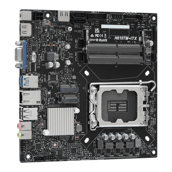
1.3 Motherboard Layout Top Side View PNL_PWR1 ATX_PWR1 SATA_1 HDMI2 DC Jack PANEL_SW1 BKT_PWR1 USB3_1_2 USB2_1_2 BLT_VOL1 SATA_2 M2_1_CT1 CLR_MOS1 H610TM-ITX RoHS SATAPWR1 DDR4_B1 M2_1_CT2 SATAPWR2 DDR4_A1 CPU_FAN1 NUT1 USB 3.2 Gen2 T: USB3_3 B: USB_TC_1 M.2 WiFi RJ-45 M.2 SSD USB 2.0... - Page 12 H610TM-ITX Back Side View M.2 SSD...
- Page 13 No. Description 4 pin 19V Power Connector (ATX_PWR1) SATA Power Connector (SATAPWR2) SATA Power Connector (SATAPWR1) SATA3 Connector (SATA_1) SATA3 Connector (SATA_2) Clear CMOS Jumper (CLR_MOS1) USB 3.2 Gen1 Header (USB3_1_2) USB 2.0 Header (USB2_1_2) FPD Brightness Header (BLT_VOL1) Backlight Inverter Voltage Selection Header (BKT_PWR1) Panel Voltage Selection Header (PNL_PWR1) Panel Off Header (PANEL_SW1) LVDS Connector (LVDS1)
-
Page 14: I/O Panel
H610TM-ITX 1.4 I/O Panel No. Description No. Description DC Jack** LAN RJ-45 Port* HDMI Port (HDMI1) USB 2.0 Ports (USB_3_4) D-Sub Port Microphone (Pink) USB 3.2 Gen2 Type-A Port (USB3_3) Line out (Lime) USB 3.2 Gen2 Type-C Port (USB_TC_1) *There are two LEDs on each LAN port. Please refer to the table below for the LAN port LED indications. -
Page 15: Chapter 2 Installation
Chapter 2 Installation This is a Thin Mini-ITX form factor motherboard. Before you install the motherboard, study the configuration of your chassis to ensure that the motherboard fits into it. Pre-installation Precautions Take note of the following precautions before you install motherboard components or change any motherboard settings. -
Page 16: Installing The Cpu
H610TM-ITX 2.1 Installing the CPU 1. Before you insert the 1700-Pin CPU into the socket, please check if the PnP cap is on the socket, if the CPU surface is unclean, or if there are any bent pins in the socket. Do not force to insert the CPU into the socket if above situation is found. - Page 18 H610TM-ITX Please save and replace the cover if the processor is removed. The cover must be placed if you wish to return the motherboard for after service.
-
Page 19: Installing The Cpu Fan And Heatsink
2.2 Installing the CPU Fan and Heatsink... -
Page 20: Installing Memory Modules (So-Dimm)
H610TM-ITX 2.3 Installing Memory Modules (SO-DIMM) This motherboard provides two 260-pin DDR4 (Double Data Rate 4) SO-DIMM slots. It is not allowed to install a DDR, DDR2 or DDR3 memory module into a DDR4 slot; otherwise, this motherboard and SO-DIMM may be damaged. -
Page 21: Jumpers Setup
2.4 Jumpers Setup The illustration shows how jumpers are setup. When the jumper cap is placed on the pins, the jumper is “Short”. If no jumper cap is placed on the pins, the jumper is “Open”. Clear CMOS Jumper (CLR_MOS1) (see p.6, No. - Page 22 H610TM-ITX Backlight Inverter Voltage 1-2 : +19V Selection Header 2-3 : +12V (3-pin BKT_PWR1) (see p.6, No. 10) Panel Voltage Selection 1-2 : +3V Header 2-3 : +5V (5-pin PNL_PWR1) 4-5 : +12V (see p.6, No. 11) Warning: If selected Backlight Power or Panel Power is higher than panel's spec, it...
-
Page 23: Onboard Headers And Connectors
2.5 Onboard Headers and Connectors Onboard headers and connectors are NOT jumpers. Do NOT place jumper caps over these headers and connectors. Placing jumper caps over the headers and connectors will cause permanent damage to the motherboard. System Panel Header Connect the power PLED+ PLED-... - Page 24 H610TM-ITX Serial ATA3 Connectors These two SATA3 SATA_1 SATA_2 (SATA_1: connectors support SATA see p.6, No. 4) data cable for internal (SATA_2: storage devices with up to see p.6, No. 5) 6.0 Gb/s data transfer rate. SATA Power Connectors Please connect SATA...
- Page 25 1. High Definition Audio supports Jack Sensing, but the panel wire on the chassis must sup- port HDA to function correctly. Please follow the instructions in our manual and chassis manual to install your system. 2. If you use an AC’97 audio panel, please install it to the front panel audio header by the steps below: A.
- Page 26 H610TM-ITX LVDS Panel Connector Signal Name Signal Name (30-pin LVDS1) LCD_VDD CLK1P (see p.6, No. 13) LCD_VDD LCD_VDD CLK2N CLK2P CLK1N Chassis Intrusion Header This motherboard (2-pin CI1) supports CASE OPEN (see p.6, No. 16) detection feature that Signal detects if the chassis cove has been removed.
- Page 27 Digital MIC Header 1: +5V (5-pin DMIC1) 2: No pin (see p.6, No. 17) 3: DMIC_CLK 4: GND 5: DMIC_DATA 6: +3.3V...
-
Page 28: Wifi/Bt Module Installation Guide
H610TM-ITX 2.6 M.2 WiFi/BT Module Installation Guide The M.2 is a small size and versatile card edge connector that aims to replace mPCIe and mSATA. The M.2 Socket (Key E) supports type 2230 WiFi/BT module. Installing the WiFi/BT module Step 1 Prepare a type 2230 WiFi/BT module and the screw. - Page 29 Step 4 Tighten the screw with a screwdriver to secure the module into place. Please do not overtighten the screw as this might damage the module.
-
Page 30: Ssd Module Installation Guide (M2_2)
H610TM-ITX 2.7 M.2 SSD Module Installation Guide (M2_1) The M.2 is a small size and versatile card edge connector that aims to replace mPCIe and mSATA. The Blazing M.2 Socket (M2_1) supports M Key type 2260/2280 M.2 PCI Express module up to Gen5 x4. - Page 31 Step 3 Peel off the yellow protective film on the nut A. Prepare the M.2 standoff that comes with the package, and hand tighten it into the nut A. Skip Step 3 if your M.2 SSD module is Type 2280. Step 4 Align and gently insert the M.2 SSD module into the M.2 slot.
- Page 32 H610TM-ITX M.2 SSD Module Support List (M2_2) M2_PCIE: Vendor Capacity ADATA 256GB ADATA ASX8200 Pro-256G ADATA 512GB ADATA SX8200 PRO-512GB (ASX8200PNP) ADATA 512GB ADATA ASX7000NPC-512GT-C (XPG SX7000) Apacer 240GB Apacer AP240GZ280-240G Crucial CRUCIAL P1-1T Crucial 500GB CRUCIAL P1-500G INTEL 16GB...
- Page 33 2.5" HDD: Vendor Capacity TOSHIBA TOSHIBA-MQ02ABD100H-MLC-NAND8G+HD1T-1T SEAGATE 500GB SEAGATE-ST500LM021-3Y/P-500G SEAGATE SEAGATE-FIRECUDA-LX015-ST1000LX015-5Y/P- 7mm-1T-W/8G 750GB WD-BLACK-WD7500BPKX-750G WD-RED-WD10JFCX-INTELLIPOWER-1T WD-BLUE-WD10SPZX-00Z10T0-1T-3Y-02 HGST HGST-HTS721010A9E630-1TB 2.5" SSD: Vendor Capacity KINGSTON 120GB KINGSTON-V300-SV300S37A-120G KINGSTON KINGSTON-HYPERX-FURY-RGB- 120GB SHFR200/240G-240G-W/RGB CABLEx1 KINGSTON 240GB KINGSTON-HYPERX-SAVAGE-SHSS37A/240G TOSHIBA 128GB TOSHIBA-Q300 PRO-HDTS412AZSTA-128G TOSHIBA 120GB TOSHIBA-Q300-HDTS712AZSTA-120G WYVO 240GB WYVO-APS1-SSB240GTLC4-SA-AF-240G...
- Page 34 H610TM-ITX Vendor Capacity UMAX 240GB UMAX-S330-HDUM330SSD240G-240G-3Y PIONEER 120GB PIONEER-APS-SL3N-APS-SL3N-120-120G-3Y ANACONDA 240GB ANACONDA-TS SERIES-TS240201803718-240G-3Y KLEVV 240GB KLEVV-NEO-N500-D240GAA-N500-240G-3Y TCELL 240GB TCELL-TT650-240G-3Y Liteon 240GB LITE-ON-MU3-PH6-PH6-CE240-L2-240G-3Y V-Color 240GB V-COLOR-VSS100-VSS100-240G-FO-240G-3Y HIKVISION 480GB HIKVISION-C100-HS-SSD-C100-480G-3Y SAMSUNG SAMSUNG-860EVO-MZ-76E250BW-MZ7LH- 250GB 250HAHQ-250G TEAM TEAM GROUP-T-FORCE-DELTA RGB- 250GB T253TR250G3C313-5V-250G-3Y...
-
Page 35: Ssd Module Installation Guide (M2_3)
2.8 M.2 SSD Module Installation Guide (M2_3) The M.2 is a small size and versatile card edge connector that aims to replace mPCIe and mSATA. The M.2 Socket (M2_3), supports M Key type 2280 M.2 SATA3 6.0 Gb/s module. Installing the M.2 SSD Module Step 1 Prepare a M.2 SSD module and the screw. - Page 36 H610TM-ITX M.2 SSD Module Support List (M2_3) M2_SATA: Vendor Capacity ADATA 512GB ADATA ASU800NS38-512GT-C Crucial 240GB Crucial-CT240M500SSD4-240GB Crucial 250GB Crucial-CT250MX500SSD4-250G ezlink 120GB ezlink P51B-80-120GB LITEON 256GB LITEON LJH-256V2G-256GB (2260) SanDisk 128GB SanDisk X400-SD8SN8U-128G SanDisk 128GB Sandisk Z400s-SD8SNAT-128G-1122 Transcend 64GB Transcend TS64GMTS400-64GB (2242)
-
Page 37: Chapter 3 Auto Driver Installer
Chapter 3 Auto Driver Installer After you install the Windows OS and boot into the system, a notification will pop up to help you to install and update required drivers. -
Page 38: Chapter 4 Uefi Setup Utility
H610TM-ITX Chapter 4 UEFI SETUP UTILITY 4.1 Introduction This section explains how to use the UEFI SETUP UTILITY to configure your system. You may run the UEFI SETUP UTILITY by pressing <F2> or <Del> right after you power on the computer, otherwise, the Power-On-Self-Test (POST) will continue with its test routines. -
Page 39: Ez Mode
4.2 EZ Mode The EZ Mode screen appears when you enter the BIOS setup program by default. EZ mode is a dashboard which contains multiple readings of the system’s current status. You can check the most crucial information of your system, such as CPU speed, DRAM frequency, SATA information, fan speed, etc. -
Page 40: Advanced Mode
H610TM-ITX 4.3 Advanced Mode The Advanced Mode provides more options to configure the BIOS settings. Refer to the following sections for the detailed configurations. To access the EZ Mode, press <F6> or click the "EZ Mode" button at the upper right corner of the screen. -
Page 41: Navigation Keys
4.3.2 Navigation Keys Use < > key or < > key to choose among the selections on the menu bar, and use < > key or < > key to move the cursor up or down to select items, then press <Enter>... -
Page 42: Main Screen
H610TM-ITX 4.4 Main Screen When you enter the UEFI SETUP UTILITY, the Main screen will appear and display the system overview. The availability and location of BIOS settings can be different for different models and BIOS versions. My Favorite Display your collection of BIOS items. Press F5 to add/remove your favorite items. -
Page 43: Oc Tweaker Screen
4.5 OC Tweaker Screen In the OC Tweaker screen, you can set up overclocking features. Because the UEFI software is constantly being updated, the following UEFI setup screens and descriptions are for reference purpose only, and they may not exactly match what you see on your screen. - Page 44 H610TM-ITX AVX2 Ratio Offset AVX2 Ratio Offset specifies a negative offset from the CPU Ratio for AVX workloads. AVX is a more stressful workload that lower the AVX ratio to ensure maximum possible ratio for SSE workloads. CPU Cache Ratio The CPU Internal Bus Speed Ratio.
- Page 45 Intel SpeedStep Technology Intel SpeedStep technology allows processors to switch between multiple frequen- cies and voltage points for better power saving and heat dissipation. Intel Turbo Boost Technology Intel Turbo Boost Technology enables the processor to run above its base operating frequency when the operating system requests the highest performance state.
- Page 46 H610TM-ITX CPU Core Current Limit Configure the current limit of the CPU core. A lower limit can protect the CPU and save power, while a higher limit may improve performance. GT Current Limit Configure the current limit of the GT slice. A lower limit can protect the CPU and save power, while a higher limit may improve performance.
- Page 47 RAS# Active Time (tRAS) The number of clock cycles required between a bank active command and issuing the precharge command. Command Rate (CR) The delay between when a memory chip is selected and when the first active command can be issued. Secondary Timing Write Recovery Time (tWR) The amount of delay that must elapse after the completion of a valid write operation,...
- Page 48 H610TM-ITX CAS Write Latency (tCWL) Configure CAS Write Latency. Third Timing tREFI Configure refresh cycles at an average periodic interval. tCKE Configure the period of time the DDR4 initiates a minimum of one refresh command internally once it enters Self-Refresh mode.
- Page 49 tRDWR_dd Configure between module read to write delay. tWRRD_sg Configure between module write to read delay. tWRRD_dg Configure between module write to read delay. tWRRD_dr Configure between module write to read delay. tWRRD_dd Configure between module write to read delay. tWRWR_sg Configure between module write to write delay.
- Page 50 H610TM-ITX tRDWR_sg Configure between module read to write delay. tRDWR_dg Configure between module read to write delay. tRDWR_dr Configure between module read to write delay. tRDWR_dd Configure between module read to write delay. tWRRD_sg Configure between module write to read delay.
- Page 51 Round Trip Level Configure round trip level. Initial RTL IO Delay Offset Configure round trip latency IO delay initial offset. Initial RTL FIF0 Delay Offset Configure round trip latency FIF0 delay initial offset. Initial RTL (MC0 C0 A1) Configure round trip latency initial value. Initial RTL (MC0 C1 A1) Configure round trip latency initial value.
- Page 52 Configure the memory on die termination resistors' PARK for channel B1. Advanced Setting ASRock Timing Optimization Configure the fast path through the MRC. ASRock Second Timing Optimization Configure the second fast path through the MRC. MRC Training Respond Time Try Slowest MRC Training.
- Page 53 Voltage Configuration DRAM Voltage Use this to configure DRAM Voltage. The default value is [Auto]. AVX Configuration AVX2 Voltage Guardband Scale Factor AVX2 Voltage Guardband Scale Factor controls the voltage guardband applied to AVX2 workloads. A value > 1.00 will increase the voltage guardband, and < 1.00 will decrease the voltage guardband.
- Page 54 H610TM-ITX global offset for the entire VF curve. In Selection modes, setting a selected VF point. Ring Voltage Offset Specifies the Offset Voltage applied to the Ring domain. This voltage is specified in millivolts. Uses Mailbox MSR 0x150, cmd 0x11. Range -500 to 500 mV.
-
Page 55: Advanced Screen
4.6 Advanced Screen In this section, you may set the configurations for the following items: CPU Configuration, Chipset Configuration, Storage Configuration, ACPI Configuration, USB Configuration and Trusted Computing. Setting wrong values in this section may cause the system to malfunction. UEFI Configuration UEFI Setup Style Select the default mode when entering the UEFI setup utility. -
Page 56: Cpu Configuration
H610TM-ITX 4.6.1 CPU Configuration Processor P-Core Information This item displays the P-Core Information. Intel Hyper Threading Technology Intel Hyper Threading Technology allows multiple threads to run on each core, so that the overall performance on threaded software is improved. Active Processor Cores Select the number of cores to enable in each processor package. - Page 57 Package C State Support Enable CPU, PCIe, Memory, Graphics C State Support for power saving. CFG Lock This item allows you to disable or enable the CFG Lock. C6DRAM Enable/Disable moving of DRAM contents to PRM memory when CPU is in C6 state.
-
Page 58: Chipset Configuration
H610TM-ITX 4.6.2 Chipset Configuration Above 4G Decoding Enable or disable 64bit capable Devices to be decoded in Above 4G Address Space (only if the system supports 64 bit PCI decoding). VT-d Intel® Virtualization Technology for Directed I/O helps your virtual machine... - Page 59 PCIE ASPM Support This option enables/disables the ASPM support for all CPU downstream devices. PCH PCIE ASPM Support This option enables/disables the ASPM support for all PCH PCIE devices. DMI ASPM Support This option enables/disables the control of ASPM on CPU side of the DMI Link. PCH DMI ASPM Support This option enables/disables the ASPM support for all PCH DMI devices.
- Page 60 H610TM-ITX Serial Port/UART Switch Select Serial Port or UART for Port 80 debug. Active LVDS This allows you to enable or disable the LVDS. Panel Type Selection Use this to select panel type.
-
Page 61: Storage Configuration
4.6.3 Storage Configuration SATA Controller(s) Enable/disable the SATA controllers. SATA Mode Selection AHCI: Supports new features that improve performance. Hybrid Storage Detection and Configuration Mode This item allows you select Hybrid Storage Detection and Configuration Mode. SATA Aggressive Link Power Management SATA Aggressive Link Power Management allows SATA devices to enter a low power state during periods of inactivity to save power. -
Page 62: Acpi Configuration
H610TM-ITX 4.6.4 ACPI Configuration Suspend to RAM Select disable for ACPI suspend type S1. It is recommended to select auto for ACPI S3 power saving. PCIE Devices Power On Allow the system to be waked up by a PCIE device and enable wake on LAN. -
Page 63: Usb Configuration
4.6.5 USB Configuration XHCI Hand-off This is a workaround for OSes without XHCI hand-off support. The XHCI ownership change should be claimed by XHCI driver. -
Page 64: Trusted Computing
H610TM-ITX 4.6.6 Trusted Computing NOTE: Options vary depending on the version of your connected TPM module. Security Device Support Use this item to enable or disable BIOS support for security device. O.S. will not show Security Device. TCG EFI protocol and INT1A interface will not be available. - Page 65 Schedule an Operation for the Security Device. NOTE: Your computer will reboot during restart in order to change State of the Device. Platform Hierarchy Use this item to enable or disable Platform Hierarchy. Storage Hierarchy Use this item to enable or disable Storage Hierarchy. Endorsement Hierarchy Use this item to enable or disable Endorsement Hierarchy.
-
Page 66: Tools
H610TM-ITX 4.7 Tools UEFI Tech Service Contact ASRock Tech Service if you are having trouble with your PC. Please setup network configuration before using UEFI Tech Service. SSD Secure Erase Tool All the SSD's listed that supports Secure Erase function. -
Page 67: Hardware Health Event Monitoring Screen
4.8 Hardware Health Event Monitoring Screen This section allows you to monitor the status of the hardware on your system, including the parameters of the CPU temperature, motherboard temperature, fan speed and voltage. Fan Tuning Measure Fan Min Duty Cycle. Fan-Tastic Tuning Select a fan mode for CPU Fan, or choose Customize to set 5 CPU temperatures and assign a respective fan speed for each temperature. -
Page 68: Security Screen
H610TM-ITX 4.9 Security Screen In this section you may set or change the supervisor/user password for the system. You may also clear the user password. Supervisor Password Set or change the password for the administrator account. Only the administrator has authority to change the settings in the UEFI Setup Utility. Leave it blank and press enter to remove the password. -
Page 69: Boot Screen
4.10 Boot Screen This section displays the available devices on your system for you to configure the boot settings and the boot priority. Fast Boot Fast Boot minimizes your computer's boot time. In fast mode you may not boot from an USB storage device. The VBIOS must support UEFI GOP if you are using an external graphics card. - Page 70 H610TM-ITX Full Screen Logo Enable to display the boot logo or disable to show normal POST messages. AddOn ROM Display Enable AddOn ROM Display to see the AddOn ROM messages or configure the AddOn ROM if you've enabled Full Screen Logo. Disable for faster boot speed.
-
Page 71: Exit Screen
4.11 Exit Screen Save Changes and Exit When you select this option the following message, “Save configuration changes and exit setup?” will pop out. Select [OK] to save changes and exit the UEFI SETUP UTILITY. Discard Changes and Exit When you select this option the following message, “Discard changes and exit setup?”... - Page 72 DECLARATION OF CONFORMITY Per FCC Part 2 Section 2.1077(a) Responsible Party Name: ASRock Incorporation Address: 13848 Magnolia Ave, Chino, CA91710 Phone/Fax No: +1-909-590-8308/+1-909-590-1026 hereby declares that the product Product Name : Motherboard H610TM-ITX Model Number : Conforms to the following speci cations:...
- Page 73 EU Declaration of Conformity For the following equipment: Motherboard (Product Name) H610TM-ITX (Model Designation / Trade Name) EMC Directive – 2014/30/EU EN 55032: 2015 / A11: 2020, EN 55035: 2017 / A11: 2020 EN IEC 61000-3-2: 2019, EN 61000-3-3: 2013...
- Page 74 EU Declaration of Conformity Product: Product Motherboard Model H610TM-ITX Authorized Representative (UK-GB): Name: Gary Tsui Address: Bijsterhuizen 11-11, 6546 AR Nijmegen,The Netherlands Contact person: Gary Tsui This declaration is issued under the sole responsibility of the mentioned Manufacturer. The subject equipment under declaration is in conformity with the UK-GB Regulation(s) below: e Electromagnetic Compatibility Regulations 2016 (S.I.